MBD Simulation on a Piston Assembly
Aim
To Create an 3D Model of Reciprocating Piston Assembly and perform motion analysis.
Introduction
Piston Assembly
Piston assembly consists of a piston, piston rings and piston pin known as gudgeon pin. It transmits force to the connecting rod and crankshaft. As piston is connected to small end of the connecting rod with the help of Wrist Pin. It guides the connecting rod when force is transmitted.
Wrist Pin Offset
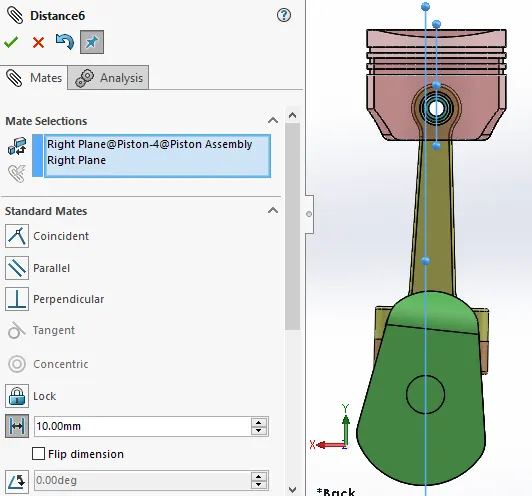
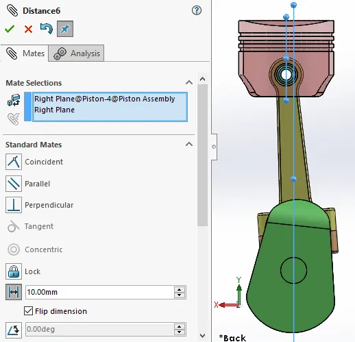
The position of the wrist pin is going to be varied as followed. But the centre of the axis of the piston head and the crank are coincident to each other (i.e.) They are on the same plane in all the three cases.
Objectives: -
- Create 3D models of Reciprocating Piston Assembly
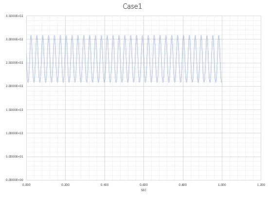
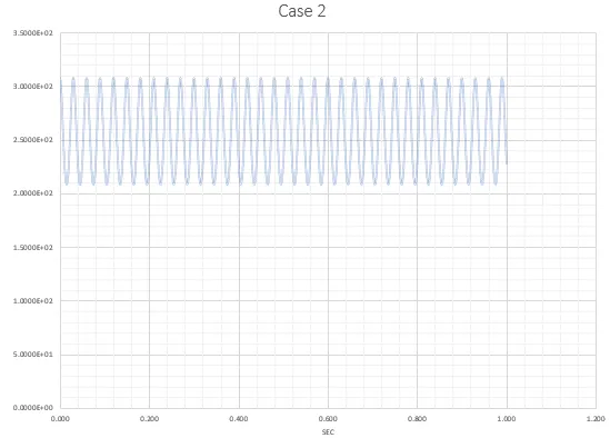
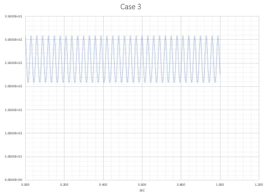
- Obtain the Linear displacement plot for the Piston Head in all the three cases:
- "0" mm Wrist Pin Offset with 2000 rpm
- 10 mm Positive Wrist Pin Offset with 2000 rpm
- 10 mm Negative Wrist Pin Offset with 2000 rpm
- Superimpose all the three graphs into a single graph.
Setup: -
- Geometry of Piston
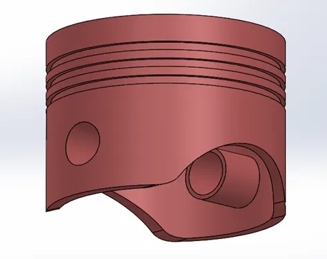
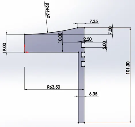
- Geometry of Connecting Rod
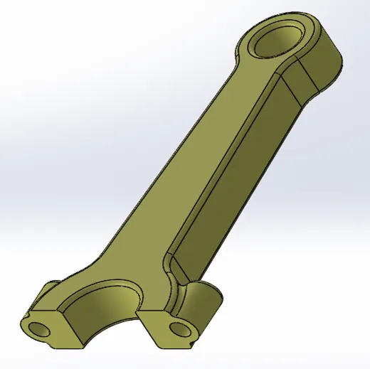
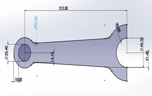
- Geometry of End Cap
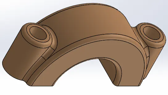
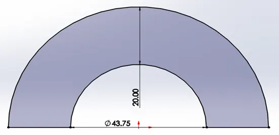
- Geometry of Wrist Pin
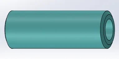
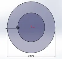
- Geometry of Crank
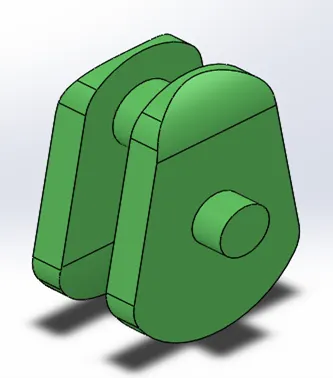
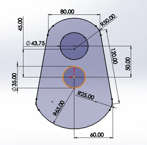
Assembly
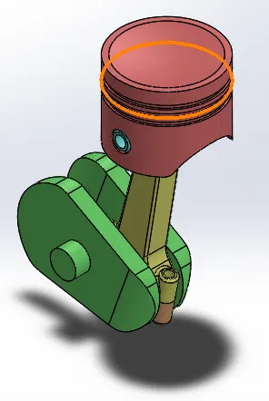
Study: - (2000 rpm)
- Case 1 - 0 mm Wrist Pin Offset
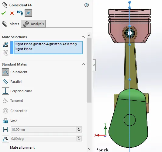
- Case 2 - 10 mm Positive Wrist Pin Offset
- Case 3 - 10 mm Negative Wrist Pin Offset
Observation and Conclusion: -
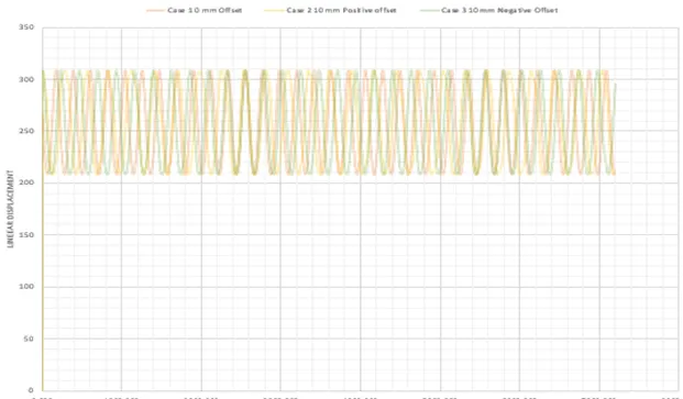
- We have finally able to get the plots for all the case.
- After Superimposing all 3 graph we can clearly see that the linear displacement of the piston is nearly the same in all cases but the starting position and the path at some duration is different.
- These offsets in mainly provided because of it‘s reduces the stress acting on the connecting rod and friction from the diagonal force pushing the piston against the cylinder wall. At the same time, this enables more effective use of the energy produced by combustion which causes more efficient mechanism in real-life application.