MBD Simulation on a Piston Assembly
Aim: Multi Body Dynamics on Piston Assembly simulation using Solidworks Motion Analysis and to obtain the plot for linear displacement of the Piston Head in all the three cases for crank speed of 2000rpm.
Software used is Solidworks 2017
Theory: Piston- Crank Mechanism is a demonstration of a simple mechanical system of linkages and motion chains. The objective is to display the working of a piston inside an engine cylinder and how the reciprocating motion of the piston gets converted to rotational motion of the crank.
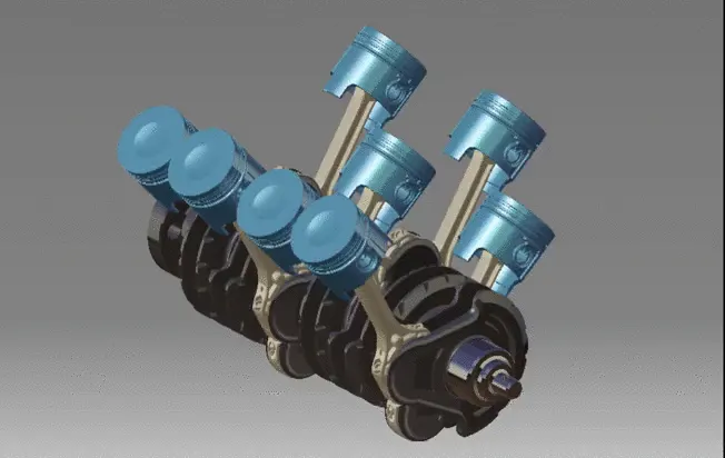
It is based on the slider crank mechanism which is an arrangement of mechanical parts designed to convert straight-line motion to rotary motion
It consists of following parts:
- Connecting Rod
- Crank
- End Cap
- Gudgeon Pin
- Piston
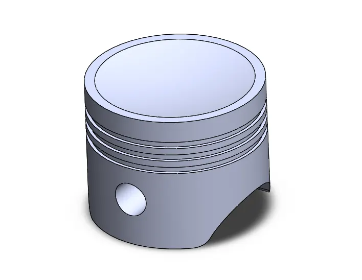
A piston is a moving disk enclosed in a cylinder which is made gas-tight by piston rings. The disk moves inside the cylinder as a liquid or gas inside the cylinder expands and contracts. A piston aids in the transformation of heat energy into mechanical work and vice versa to the crank via connecting rod.
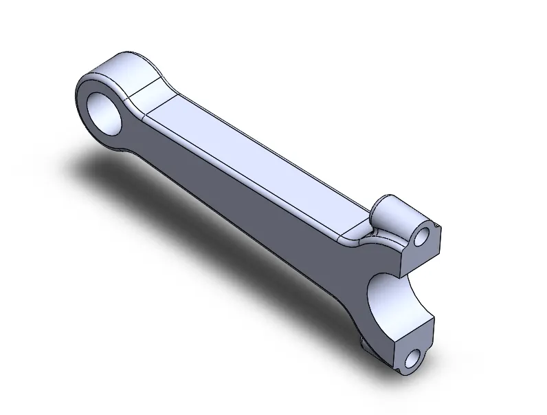
1.Connecting Rod: A connecting rod, also called a con rod, is the part of a piston engine which connects the piston to the crankshaft. Together with the crank, the connecting rod converts the reciprocating motion of the piston into the rotation of the crankshaft.
2.Crank: The crankshaft is a moving part of the internal combustion engine (ICE). It's main function is to transform the linear motion of the piston into rotational motion. The pistons are connected to the crankshaft through the connecting rods. The crankshaft is mounted within the engine block.
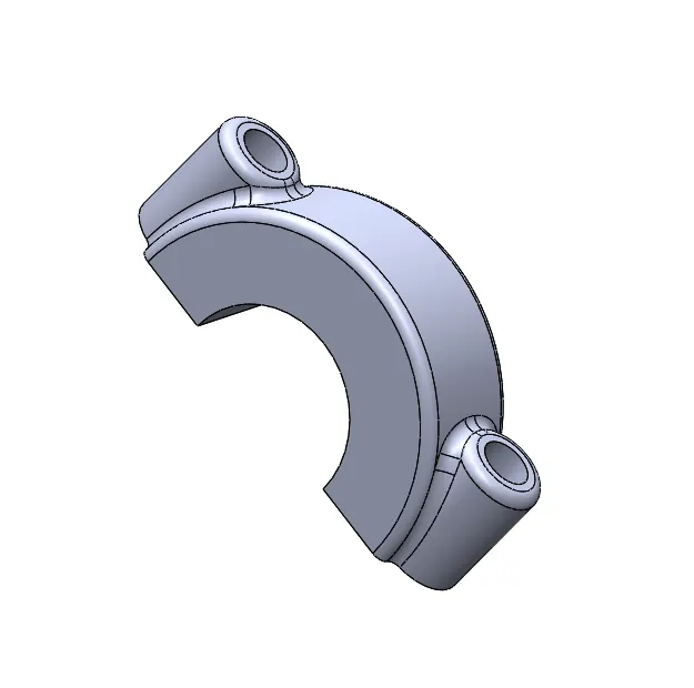
3.End Cap: The small end of the connecting rod connects to the piston with a piston pin. The piston pin, or wrist pin, provides a pivot point between the piston and connecting rod. The rod cap is attached to the connecting rod with two cap screws for installation and removal from the crankshaft.
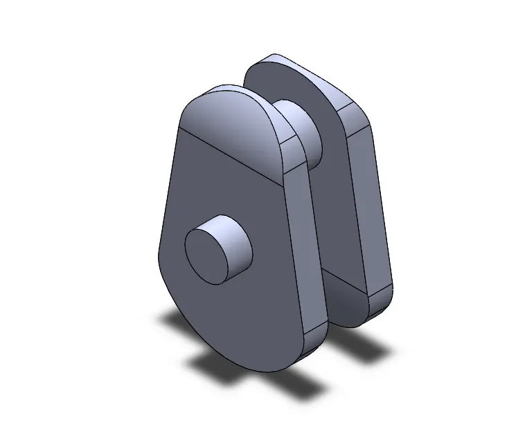
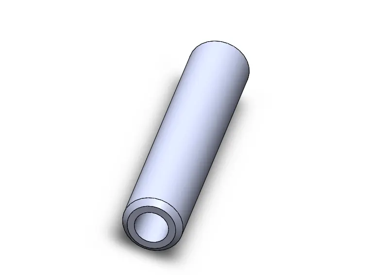
4.Gudgeon Pin: The gudgeon pin is typically a forged short hollow rod made of a steel alloy of high strength and hardness that may be physically separated from both the connecting rod and piston or crosshead. The design of the gudgeon pin, especially in the case of small, high-revving automotive engines is challenging. The gudgeon pin has to operate under some of the highest temperatures experienced in the engine, with difficulties in lubrication due to its location, while remaining small and light so as to fit into the piston diameter and not unduly add to the reciprocating mass. The requirements for lightness and compactness demand a small diameter rod that is subject to heavy shear and bending loads, with some of the highest pressure loadings of any bearing in the whole engine. To overcome these problems, the materials used to make the gudgeon pin and the way it is manufactured are amongst the most highly engineered of any mechanical component found in internal combustion engines.
5.Piston: A piston is a moving disk enclosed in a cylinder which is made gas-tight by piston rings. The disk moves inside the cylinder as a liquid or gas inside the cylinder expands and contracts. A piston aids in the transformation of heat energy into mechanical work and vice versa.
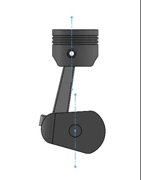
Piston CRANK assembly
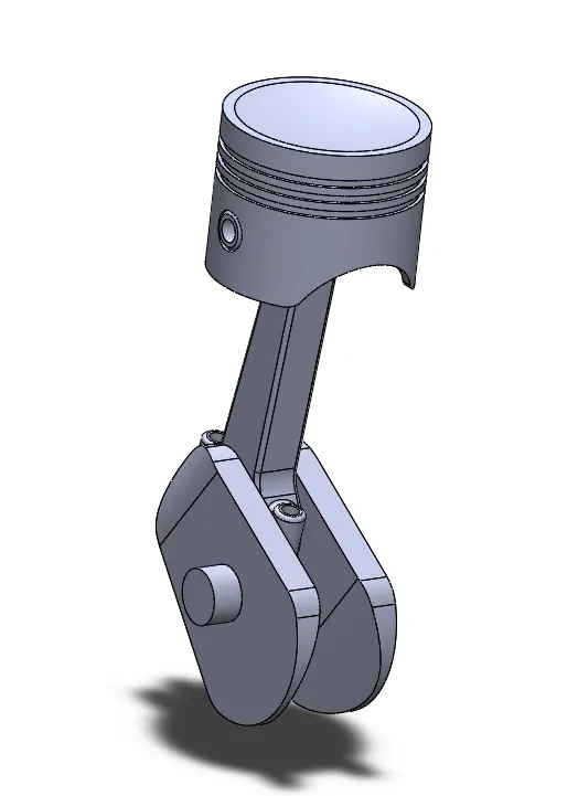
VIDEO SHOWING EXPLODED VIEW OF THE PISTON CRANK ASSEMBLY
After designing all the parts we have to complete the assembly.
This project aims to analyze the motion analysis of the piston and the parameters set to achieve the plots of linear displacement are given below:
Motion Study Analysis
The motion study: In the Motion study the following steps are performed.
- Select motion analysis in the drop-down menu.
- Motor is given to crank with the speed 2000 RPM.
- Frames per second are given as 12000 with precise contact.
- Contact is given between endpin and crank, crank and connecting rod, connecting rod and wrist pin and wrist pin and piston. The material selected for each case is steel (Dry).
- Gravity in the Y direction.
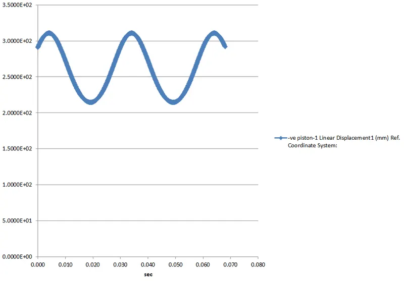
Calculation is performed for the motion analysis for about 3 sec. Linear displacement of the piston head w.r.t time is obtained.
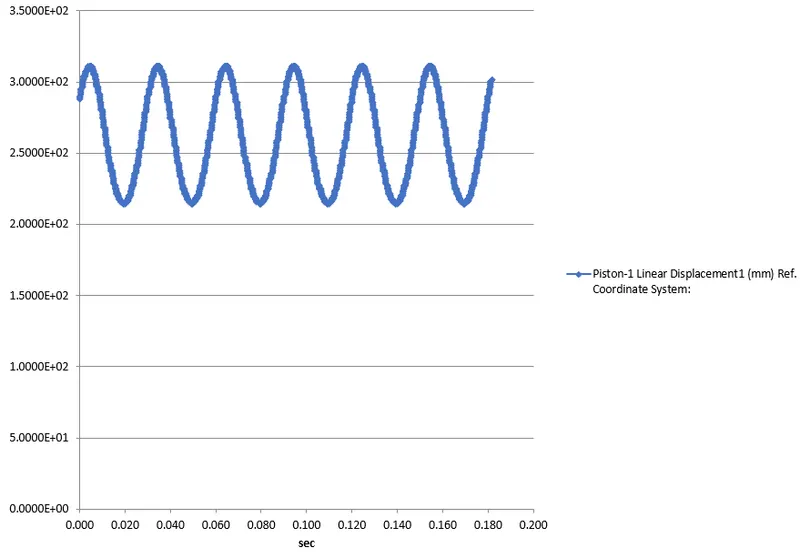
Case 1: Motion Analysis for "0" mm Offset
->Crank speed 2000Rpm clockwise
->Frames per second 12000
-->Gravity 9.8m/s^2 in the y direction
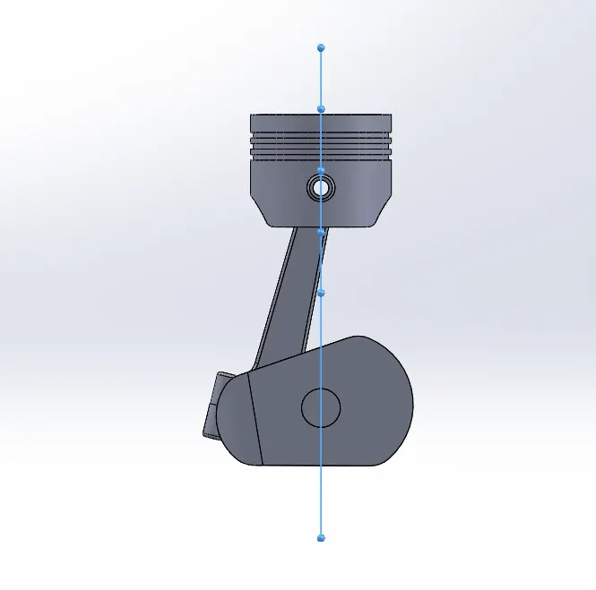
Plot for linear displacement of the piston head as a function of time
Case 2: Motion Analysis for "10" mm positive Offset
->Crank speed 2000Rpm clockwise
->Frames per second 12000
-->Gravity 9.8m/s^2 in the y direction
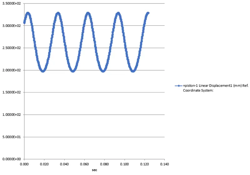
Plot for linear displacement of the piston head as a function of time with 10mm positive offset
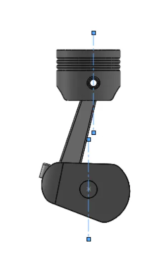
Case 3: Motion Analysis for "10" mm negative Offset
->Crank speed 2000Rpm clockwise
->Frames per second 12000
-->Gravity 9.8m/s^2 in the y direction
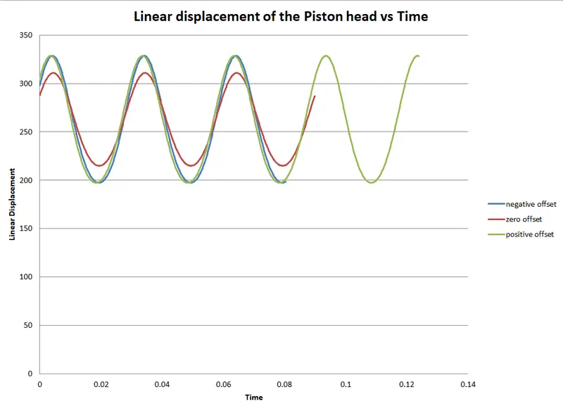
Superimposed plot
Results and conclusion
From the above superimposed graph it is clear that the for positive and for negative the linear displacement of the piston is almost similar,also it is quite clear that the starting position of the piston increases as we provide an offset to it either it be negative or positive ,the graph obtained is smooth and clearly shows the motion of the piston over interval of times.
The linear displacement plot of the piston head displayed a sinusoidal curve.
The maximum displacement obtained by the piston will be the case when there will be zero offset although the difference is negligible .
Google drive Files
https://drive.google.com/drive/u/0/folders/1oD6KxIidFWXuMHeMICpZctITXCJ0aaLr