MBD Simulation on a Piston Assembly by using SOLIDWORKS
AIM :
To create a piston kinematics components and assembling the component with each other, performing a motion analysis for different wrist pin distance and also make a plot for piston linear displacement.
FLOW OF CONTENT/METHODOLOGY :
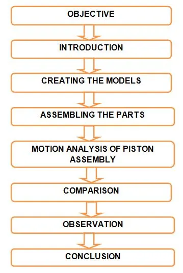
OBJECTIVES :
1) Create a indivdual parts for making an piston assembly like piston, gudgeon pin, connecting rod, end cap and crank.
2) Assembling the parts in proper manner and provide the gudgeon pin offset distance for our concern.
3) Performing the motion analysis for all cases.
4) Extracting the data and make it into plot.
INTRODUCTION :
PISTON :
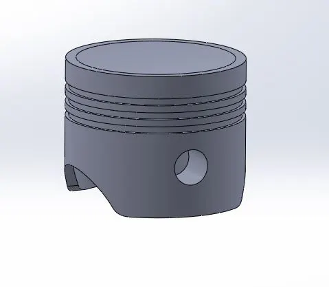
It is a main active part of the engine.It is a cylindrical shape mass that reciprocates inside the cylinder. Pistons are long hollow objects, open at the bottom and closed at the top. The top portion of the piston is called 'Crown' . From the piston top, three grooves are cut to accomodate the piston rings. The bottom portion of the piston is called 'Skirt'. In the middle portion gudgeon pin bosses are provided with bearing surface, groove provisions are cut to accommodate the piston rings. Pistons are slightly smaller in diameter than the cylinder bore. The space is provided between piston and cylinder wall is called clearance. This clearance is necessary for adherence of a flim of lubricant.
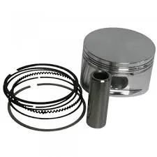
Function of piston :
1) To compress the fresh charge during the compression stroke.
2) To transmit the force of combustion gases (explosion) to the crank shaft.
3) To form a seal so that high pressure burnt gases in the combustion chamber do not escape into the crank case.
4) It acts as a bearing for the gudgeon pin.
Materials for made a piston :
Pistons are made of aluminium alloy, cast steel, grey cast iron, chrome nickel alloy & Nickel iron alloy. Aluminium alloy pistons are mostly used in modern automobiles. They are manufacturing by casting or forging methods.
PISTON PIN OR GUDGEON PIN OR WRIST PIN :
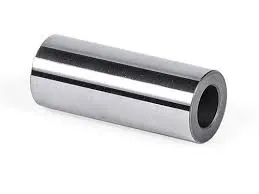
The piston pin is used to connect the piston and the connecting rod small end. The another name of the piston pin is wrist pin or gudgeon pin. It transfers combustion chamber preesure and piston forces to the connecting rod.
It is made in tubular form. It is having less weight. It makes a joint between the bosses in the piston and the small end of the connecting rod. It bears side thrust.
Material for made a piston pin :
It is made of low carbon cast hardened steel.
CONNECTING ROD :
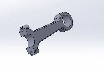
Connecting rod is the intermediate link or connecting element between the crank shaft and the piston. The expanding gas force on the piston is thus transmitted to the crank pin through this rod. It has two ends namely small end and bigger end. The small end is connected to the piston through gudgeon pin. The big end of the connecting rod is fastened to the crank pin in the crank shaft through the cap, rod bolts and nuts. The connecting rod usually has circular cross section.
The connecting rod while transmitting the thrust from the piston to the crank shaft must be able to maintain the shape rigidly combined with higher strength.
The connecting rod have better tensile strength and compressive strength.
Function of connecting rod :
It is used to convert reciprocating motion of the piston into rotary motion of the crank shaft.
Material for made a connecting rod :
It is made of forged steel, Medium carbon steels, aluminum alloys and nickel alloys steels are commonly used materials
CRANK SHAFT :
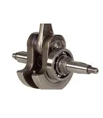
It is used to convert reciprocating motion of the piston into rotary motion. Big end if the connecting rod to crankshaft. On rear end of the crank shaft a flywheel is mounted which acts as an energy reservoir. On the front end of the crank shaft, a timing gear or sprocket, a vibration damper and a pulley for driving the water pump, fan and alternator are mounted.
Function of crank shaft :
The function of a crank shaft is to convert reciprocating motion of the piston into rotary motion.
Material for made a crank shaft :
These are usually made in one piece. Crank shaft are cast or drop forged from mild steel. After casting or forging, they are siutably heat treated ( case hardened )
CREATING THE MODELS :
Creating the piston :
First of all, create the 2d sketch with appropriate dimensions and convert into 3d solid part by using an revolve option. Create a circle on right plane by using extrude cut option to cutout from piston for insering a wrist pin or gudgeon pin or piston pin.
Create a ring groves for insert the compression and oil ring for tightly enclosed into engine cylinder by using linear pattern option. Most of the option are used for making an piston is circle, line, extrude boss base, extrude cut, linear pattern entities and 3 point arc.
Creating the connecting rod :
Create a smaller and bigger circle with defining the constrains, draw the tangent line from smaller circle to bigger circle and provide constrains. Extrude the sketch and built the bolt cap. The connecting rod is help to convert from linear motion to rotary motion.
Creating the crank :
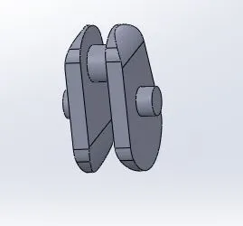
A crank is rotating part, the crank pin connects into connecting rode big end. The crank pin is placed some eccentric distance. Most of the option are same for making an crank.
Creating the End cap :
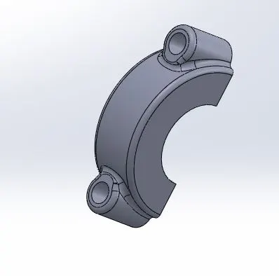
The end cap is helps to enclosed the crank pin with bolt and nuts. Create a two circle with fully defining and extrude it, additionally bolt cap is fixed with eachother. Most of the sketching option is same.
ASSEMBLING THE PARTS :
1) Open the assemble window, import the crank and coincident the crank axis into assembly right and top plane with that coincident the front plane of crank and front plane of assembly plane.After that, import the remaining parts in simultaneously such as connecting rod, piston, gudgeon pin and End cap.
2) Combine the end cap and connecting rod big end in a single part. Make coincide the crank pin axis and big end axis and also mate the crank pin outer surface and big end inner surface.
3) Mate the connecting rod front plane and crank front plane and also mate the connecting rod front plane and piston front plane, coincident the piston slot axis and gudgeon pin.
4) Mate the front plane of a piston and front plane of a gudgeon pin, coincident the connecting rod small end axis and gudegeon pin axis. Mate the connecting rod front axis and gudgeon pin front axis.
5) Select the right plane of crank and right plane of piston, to provide the offset based on over concern.
CASE 1
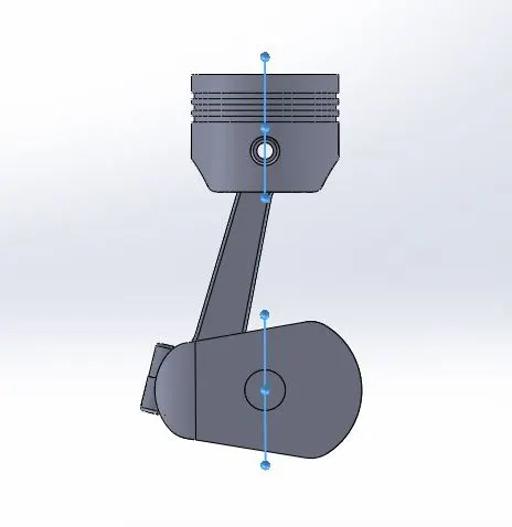
Distance between the wrist pin and crank axis is zero :
Select the right plane of a piston and right plane of a crank, to provide a offset distance is Zero. To run the motion analysis and plot it down the linear displacement of piston inside the engine cylinder.
CASE 2
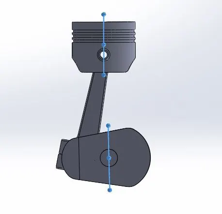
Distance between the wrist pin and crank axis is positive 10 mm offset :
Select the right plane of a piston and right plane of a crank, to provide a positive offset distance is 10 mm. To run the motion analysis and plot it down the linear displacement of piston inside the engine cylinder for in this case.
CASE 3
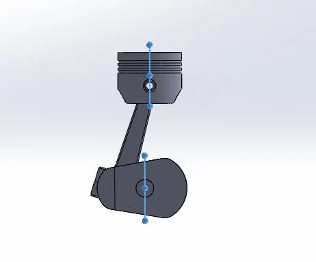
Distance between the wrist pin and crank axis is Negative 10 mm offset :
Select the right plane of a piston and right plane of a crank, to provide a negative offset distance is 10 mm. To run the motion analysis and plot it down the linear displacement of piston inside the engine cylinder for in this case.
MOTION ANALYSIS OF PISTON ASSEMBLY :
First of all, addins motion study setup into the solidworks, change the animation to motion analysis. To provide the speed to crank axis at 2000 RPM for all the cases and set the frames per second is 12000. To select the all, set the contact selection and material is Dry steel. To set the adequate motion analysis study time and click to calculate.
POST PROCESSING :
CASE 1
Youtube link for case 1 : https://www.youtube.com/watch?v=rHM_3I2lkT4
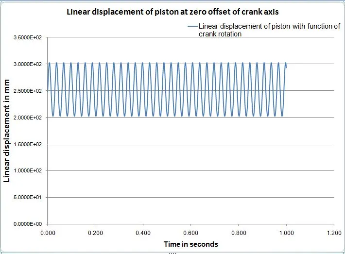
Linear displacement of piston at zero offset :
After the completion of calculation, make a plot to linear displacement of the piston at enclosed engine cylinder. The piston kinematics is a function of crank angle or crank rotation. It looks like a cosinusoidal, because it start from natural number. The displacement varies depends on crank rotation.
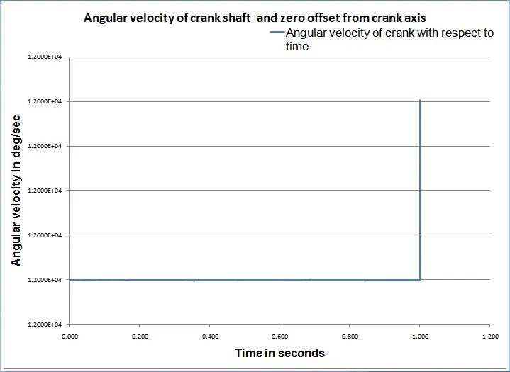
Angular velocity of crank at zero offset :
A angular velocity of crank is constant over the time duration.
CASE 2
Youtube link for case 2 : https://www.youtube.com/watch?v=XpAN7S1C09c
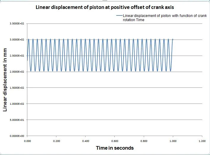
Linear displacement of piston at positive 10 mm offset :
A crank axis and plane is fixed, it will not to move. The piston right plane is step away on left side at distance of 10 mm from the crank right plane, but the both planes are parallel to each other.
The Number of cycle is higher than the Zero offset case. Otherwords, the time taken for complete one cycle is lesser than the Zero offset case.
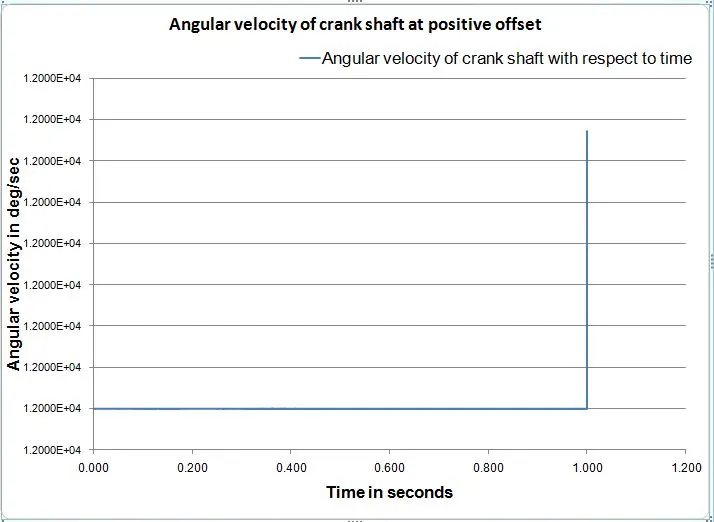
Angular velocity of crank at positive 10 mm offset :
A angular velocity of crank speed is constant over the time duration. Because, it is input for our cases.
CASE 3
Youtube link for case 3 : https://www.youtube.com/watch?v=IUw5qLypcDk
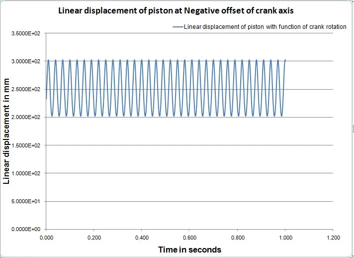
Linear displacement of piston at negative 10 mm offset :
A crank axis and plane is fixed, it will not to move. The piston right plane is step away on right side at distance of 10 mm from the crank right plane, but the both planes are parallel to each other.
The Number of cycles is equal to previous case. Otherwords, the time taken for one complete cycle is equal to previous case cycle also.
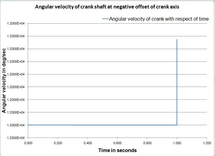
Angular velocity of crank at negative 10 mm offset :
A angular velocity of crank is constant over the time duration.
COMPARISION :
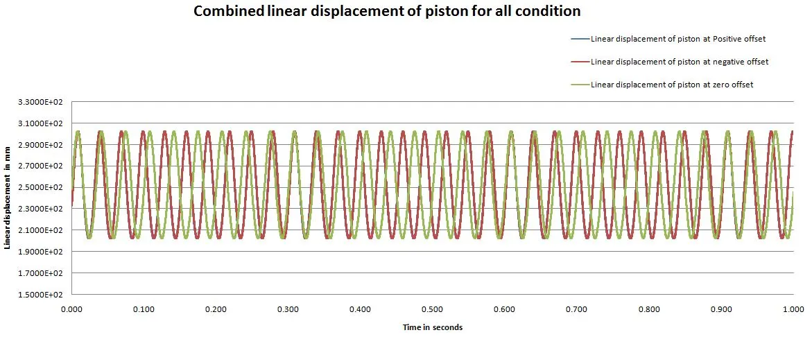
Superimposed linear displacement time duration range is 0 - 1 :
A zero offest, positve & Negative offset are sperimposed into single graph, the linear diplacement of a positive offset and negative offset are overlapped each other. The Positive and Negative offset case has been completes more cycles compared to Zero offset cases. The linear displacement curves are closely printed, we wouldn't look exactly.
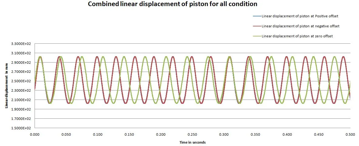
Superimposed linear displacement time duration range is 0 - 0.5 :
This image is same as that see in above image, I had been reduced the time span range. It looks clearly visible the variation of three different cases. Even more, it's not visible the exact variation. The linear displacement of piston at negative offset is exactly overlapped into Linear displacement of piston at positve offset.
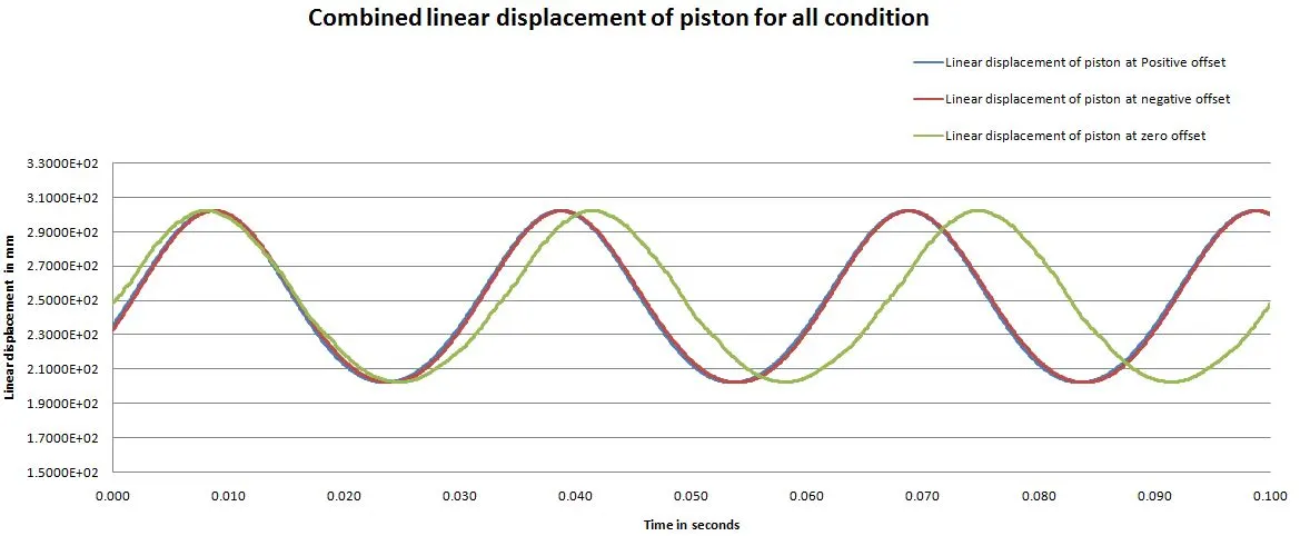
Superimposed linear displacement time duration range is 0 - 0.1 :
To reduce the time range from 0 to 0.1, the linear displacement path is almost same for positive offset and negative offset. Zero offset case takes more time to completes the one cycle Or otherwords, the linear displacement of positive or negative offset has more number of cycles compared to Zero offset case.
OBSERVATION :
1) The Linear displacement of positive offset & Negative offset output has almost same along the time duration and number of cycles are higher than the Zero offset case.
2) We set either positive offset location or negative offset location, that gives same output. In both cases, the number of cycles are same.
3) The output is vary when we made the piston assembly is Zero offset. The number of cycles is same.
4) All the cases curves are look like a cosinusoidal.
CONCLUSION :
Finally, to ran the motion study for three different condition in separately with extracting the data from the model and plotted it. Comparing the all the cases in the superimposing plot, the zero offset case performance is lesser than the remaining two case. If, we use positive offset place or negative offset place, the output result has been same.
PISTON ASSEMBLY MODEL LINK : https://drive.google.com/drive/folders/1OVSS3Vi6VztBJKsQijNJUGwRKN6dCcEx?usp=sharing