MBD Simulation on a Piston Assembly
AIM:
To model piston assembly and run motion analysis for the following cases:
(i) 0mm wrist pin offset.
(ii) 10mm wrist pin offset.
(iii) -10mm wrist pin offest.
THEORY:
An IC Engine is that kind of prime mover which converts chemical energy of fuel to mechanical energy. The fuel on burning changes to gas which impinges upon the piston and pushes it to case reciprocating motion. The reciprocating motion of the piston is converted to rotary motion of the crankshaft with the help of slider mechanism involving connecting rod and crank.
IC Engines are used in marine, locomotive, aircraft, automobile and other industrial applications. Several types of IC engines are used on various automobiles.
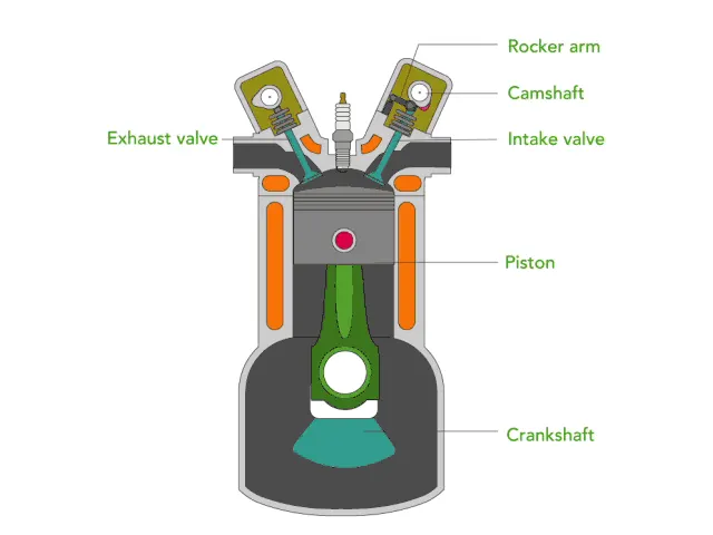
Description of Selected Components of an IC Engine:
Piston:
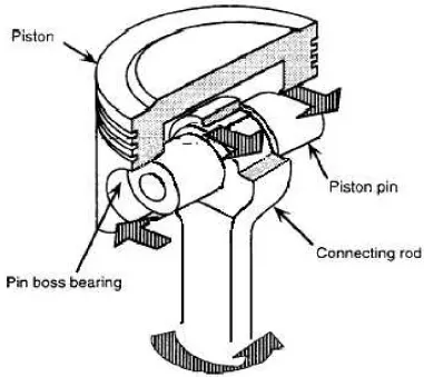
The gas force produced during power stroke acts on the piston. Its parts are crown, head with groves (some times called ring belt) for rings, skirt and piston pin bosses and ribs.
The details of the piston can be seen below:
The piston crown must be thick enough to withstand the gas forces and also to transmit the heat transferred to it during the combustion to the ring belt. The gas load gets transferred to the piston bosses through the ribs. The heat gets transferred to the cylinder walls through the ring belt and the rings.
Piston of engines are made of alloy steel, alloy cast iron or aluminium alloy. Different aluminum alloys used for pistons are SAE300, Y alloy, SAE 301, Low expansion alloy- HG 413, Low expansion alloy HG 416. In these Al alloys, various metallic compounds are added to improve their properties. Nickel and Copper increase thermal stability and improve to some extent mechanical properties at high temperatures. Alloys with silicon have lower coefficient of thermal expansion. At present Al alloy piston is more popular since its heat conductivity is higher and inertia forces are lower.
CRANKSHAFT:
Crankshaft is a rotating component to which is connected is the crank. The crank shaft receives the power produced in the engine for onward transmission in the transmission system. The power comes to it from the connecting rod and is then transferred to the clutch through a flywheel, which is mounted on it. Crank pins in a crank shaft are eccentrically located with respect to the axis of the crank shaft. The eccentricity is called throw of the crank. Provision of crank web is made to counter act the tendency of bending of the crank shaft due to centrifugal action during engine operation. The crank shaft is of either built in type or a single piece type. A single piece construction is more common. The crankshafts are generally made by forging of medium carbon alloy steels. They are then induction hardened ensure uniform hardness and are checked for balance in the dynamic balancing machine.
CONNECTING ROD:
The small end of the connecting rod is connected to the piston and the big end is connected to the crank shaft through the crank pin. The connecting rod in operation is subjected to combined axial and bending stress. The combustion gas pressure and the inertia forces on account of reciprocating motion produce axial stress while the bending stresses are developed due to the centrifugal action. The cross-section of the connecting rod is made I to provide improved rigidity and reduce the weight. The connecting rods are manufactured by either by drop forging process or by casting. Alloy steel or aluminium alloy are used for making connecting rods.
GUDGEON/WRIST PIN:
The piston pin -also known as the gudgeon pin- transfers the entire generated power out of the combustion process from the piston, via the connecting rod down to the crankshaft. Due to the fact that the piston pin does not rotate, it is the engine component that have to withstand the highest stresses in engine operation. The piston pin connects the piston and the connecting rod and must withstand extremely high loads in changing directions. It is commonly made out of case-hardening or nitraded steel with a hardened, smooth ground and polished surface.
In order to withstand the occuring loads out of the combustion process as well as the continuous increasing firing pressures, it is essential to permanently optimize the load-bearing capacity of this component..
Piston pins are characterized by precision, application diversity and the highest material quality.
Due to the oscillating forces of the ignition pressure and mass inertia forces in the opposite direction, the piston pin is bent through, oval-shaped and subjected to shear. The piston pin boss can be damaged by excessively large deformations of the piston pin, which can lead to the complete destruction of the piston.
Only in the case of small bolt deformations, the stresses remain below the permissible values.
The piston pin is mounted for power transmission in the pin bore of the piston and the connecting rod. The optimal clearance between piston pin and pin boss as well as connecting rod bush is very important for the function. Also the surface roughness has to be very low. Therefore, it is recommended for checking this on a regular basis.
For high speed engines, with stresses higher than in medium speed engines, coatings made of DLC (Diamond-like-Carbon) have been developed to minimize the friction between piston pin and connecting rod respectively their bearing bushes.
GEOMETRICAL SETUP:
Piston
1)Open Solidworks. Create a new model. Select the front plane and create a new sketch.
2)Using line tool and 3-point arc tool create sketch as shown below.
3) Exit sketch and use the Revolved Boss/Base option. Then select the front plane again and create a new sketch.
4) Draw a rectangle of length 2.5mm and breadth 5mm. Make one edge collinear with the corner of the solid. The vertical distance between the origin and bottow edge is 5mm. Then draw a vertical construction line from the origin.
5) Exit sketch and use the Revolved Cut option, axis being the vertical line. A cut is made in the piston.
6)Use the Linear Pattern option, reference as top plane and make 3 such instances of this pattern.
7) Select the front plane and create a new sketch. Draw a circle of diameter 25.4mm, 40mm below the origin. In case 1, the centre of the circle is vertical with the origin, in case 2 the centre of the circle is 10mm to right of the origin and in case 3 the circle is 10mm to the left of the origin.
8) Exit sketch and use extruded cut option. It should be from Mid Plane and should be extruded by 63.5*2 mm.
9) Select the right plane and create a new sketch. Select a three point arc and draw it in such a way that the two points are horizontal to each other. coinciding with the bottom edge and the centre of the arc is vertical with the origin. Make distance between the centre and one point as 42mm and make radius of the curce as 45mm.
10)Exit sketch and use extruded cut option. Extude Through all-Both and select Flip side to cut. The sharp corners need to filleted. Keep fillet radius as 10mm.
11) Select Front Plane and create new sketch. Click the hole and and select the convert entities option. It is converted into an entity. Select the cirlce and then click on the offset entities option. Keep offset distance as 2.5mm.
12)Exit sketch and extrude. Keep offset of 30mm. Under Direction 1, Select Upto Surface. Under surface select the outer surface of the piston. Flip the direction and click ok. Mirror this extrusion with front plane as mirror face. This is a rest for the gudgeon pin.
13) Piston is ready.
Case 1
Case 2
Case 3
Connecting Rod and End Cap:
1) Open a new part model. Select the Front Plane and make a new sketch. Use circle tool, line tool and mirror tool to draw the following sketch. (The other half of the bigger semi circle will become the end cap, do similar steps to get it).
2) Exit sketch. Extrude from Mid Plane by 30mm.
3) Select the face of the semi circular part. Create a sketch. Draw two circles of diameter, each whose centre lies on the edge of the two rectangular faces and are vertical to origin. Exit sketch and extrude it by 30mm in the direction towards the other circular face. Select the same rectangular face again and sketch two circle concentric to the previous circles. Exit sketch and make extruded cut of 30mm. Fillet the corners of the connecting rod using fillet radius of 27mm.
4) Repeat the same steps for end cap.
Connecting Rod End Cap
CRANK:
1) Open a new part model. Click on the Front plane and make a new sketch. The sketch should be as bellow.
2) Exit sketch. Extrude by 20mm. Fillet the 4 corners with radius 25mm.
3) On one face of draw a circle of diameter 43.75mm, 50mm above origin. Extrude it by 16mm. On the other face draw a circle of diameter 35mm with centre lying on origin. Extrude by 20mm.
4) On the right plane 2 3-point arcs have to be drawn as shown below and should then be extrude cut.
First Curve:
2nd Curve:
5) Now, we have to mirror the entire thing. Mirror Face is the the 43.75mm circular extrusion.
GUDGEON PIN:
1) In a new part model, draw two concentric circles. The diameter of the outer circle should be 25.4mm and the distance between inner and outer circle shouldb be 5.5mm.
2)Extrude it from Midplane by 127mm. Chamfer the two corners by 2.5mm.
ASSEMBLY:
1) Open a new assembly model. Load the crank. View all temporary axis. Right click the crank shaft and and select float. Coincide the axis of the crank with the Right plane and the Top Plane of assembly.
2) Select the Front Plane of the crankshaft and FP of assembly and make the perpendicular distance between them as 36mm.
3) Insert the connecting rod and the end cap. Coincide the axis and face of the connecting rod and end cap.
4)Now coincide the axis of the bigger circle of the connecting rod and the axis of the crank shaft.
5) Make the perpendicular distance between one face of the connecting rod and one face of the crank shaft as 1mm.
6)Insert the gideon pin and the piston. Coincide the axis and the Front planes of the gideon pin and the piston.
7) Coincide the centre axis of the other side of the connecting rod and the piston. Also coincide the Front Planes of the connecting rod and the piston.
8) Finally coincide the Right planes of the piston and assembly.
Case 1:
Case 2:
Case 3:
MOTION ANALYSIS:
1)Select Solidworks Add-Ins and click Solidworks motion. Go to Motion study and make type of motion study as Motion analysis.
2) Select Motor option. Under reference, select axis of crank. Make speed 2000 rpm.
3) Under settings, make frame speed as 12000 fps. Allow precise contact.
4) Select Contact. Make contact between crank and end cap, crank and connecting rod, connecting rod and gideon pin and gideon pin and piston. All the parts are made of Steel (Dry).
5) Enforce gravity, acting in the Y-direction.
6) Calculate results for all three cases.
RESULTS:
Case 1:
Linear Displacement of Piston vs Time
Video Link: https://www.youtube.com/watch?v=2c06Fwz_J60&feature=youtu.be
Case 2:
Linear Displacement of Piston vs Time
Video Link: https://www.youtube.com/watch?v=dB-w283JrDo&feature=youtu.be
Case 3:
Linear Displacement of Piston vs Time
Video Link: https://www.youtube.com/watch?v=JqiqJAXcVT0&feature=youtu.be
Superimposed Graph:
INFERENCE:
(i) In all three cases the maximum value of linear displacement of piston head is 311mm and the minimum value is 215mm.
(ii) The curve of case 1 is leading, followed by case 2 and finally case 3. Case 3 is lagging the most.
REFERENCES:
https://www.diesel-engine-motor-service.com/en/about-seco/24-support/245-part-6-piston-pin.html