MBD Simulation on a Piston Assembly
Aim:
To conduct a Multi Body simulation on a Piston Assembly
Introduction:
An internal combustion engine (ICE) is a heat engine in which the combustion of a fuel occurs with an oxidizer (usually air) in a combustion chamber that is an integral part of the working fluid flow circuit. In an internal combustion engine, the expansion of the high-temperature and high-pressure gases produced by combustion applies direct force to some component of the engine. The force is applied typically to pistons, turbine blades, rotor or a nozzle. This force moves the component over a distance, transforming chemical energy into useful work.
Étienne Lenoir created the first commercially successful internal combustion engine around 1860 and it created the first modern internal combustion engine in 1876 by Nicolaus Otto

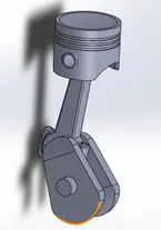
Functions of Piston Assembly, Connecting rod and crankshaft
PISTON ASSEMBLY
Piston assembly comprises a piston, piston rings and piston pin known as gudgeon pin.
Functions of piston assembly are given below:
*It transmits gas force generated during combustion to the connecting rod and crankshaft.
*As piston is connected to small end of the connecting rod with the help of gudgeon pin. It guides the connecting rod when gas force is transmitted.
*Air/fuel mixture is compressed by piston.
*Piston rings restrict the flow of hot gases into the crankcase. This is also referred as blow by control.
*Piston rings lubricate the cylinder wall.
*Piston rings restrict the amount of oil from crankcase into the gap between piston and cylinder head.
*Heat is transferred to the cylinder wall from piston by piston rings. [4]
Piston construction
Piston top is the part of combustion chamber. Top portion can be a flat or bowl is provided as per the combustion requirement. Grooves are provided in the ring belt area to accommodate piston rings. The heat flows from crown, out of the ring belt. Heat is transferred to the cylinder walls through piston rings and then small portion is transferred to the skirt. Some amount of heat is also taken by the lubricant.
Piston rings
There are two types of piston rings: compression and oil control ring. Piston rings are generally made up of rectangular section. To prevent sticking of ring into the groove, their inner and outer edges are chamfered. Compression rings are subjected directly to gas pressure.
Gudgeon Pin or piston pin
Gudgeon pin is the main load carrying part in piston assembly. Small end of the connecting rod is connected to piston with the help of gudgeon pin.It consists of aluminum pads are placed at the ends; these will not damage the cylinder. In order to maintain a correct fit between piston and connection rod, external surfaces of gudgeon pins are finished to a high degree of accuracy.
Connecting Rod
The main function of a connecting rod is to form a link between a piston and crankshaft. A small end of the connecting rod is connected to the piston with gudgeon pin and big end is separated into two parts for ease of assembly with crankpin. The two parts of the big end are bearing cap and big end housing. Both are being bolted together. This is done for ease of assembly of connecting rod with crankpin. To supply oil to the big end, the oil hole is drilled from big end. A typical arrangement of connecting rod is given below
Construction of a connecting rod
Crankshaft
Crankshaft is the final link in the slider crank mechanism. The linear motion of a piston is converted into rotary motion of a crankshaft. The energy is generated into the combustion chamber by transforming the reciprocating motion of a piston into rotary motion of a crankshaft. Crankshaft consists of two main bearings at the other side of the it, made up in to two half liners. Crankshaft, crankshaft oil seals, main bearings, pulley and vibration damper are parts of crankshaft assembly. [4]
Crankshaft and main bearings
IN SERVICE CONDITIONS OF PISTON ASSEMBLY, CONNECTING ROD AND CRANKSHAFT
PISTON ASSEMBLY
Pistons are subjected to mechanical load, thermal load and side load. During combustion stroke high pressurised gases are formed. Mechanical loading is due to these high pressurised gases and the reaction from the pin and cylinder wall. Thermal loading is due to the temperature and heat transfer conditions in the cylinder. Heat flux is a measure of thermal loading. Articulation of the connecting rod results in a side loading.
Different operating conditions of a piston are given below:
Max operating pressure: Up to 80 to 110 bars in case of naturally aspirated engines, 130 to 180 bar in case of supercharged diesel engines.
Max operating temperature: Peak gas temperature is between 300 to 400°C
Pistons are also subjected to mechanical and thermal stresses. Temperature distribution on the top of the piston is uneven. These loads and stresses are repeated every cycle and can vary with speed. This induces fatigue stress into piston and gudgeon pin.
CONNECTING ROD
● Connecting rod is subjected to;
● Load due to gas pressure on a piston.
● Inertia load due to reciprocating parts and piston.
● Inertia load due to connecting rod weight itself.
● Force due to friction of piston rings and piston.
● Force due to friction of gudgeon pin bearing and crankpin bearing which increase the compressive stress on the connecting rod.
Bending stress and tensile stress is developed due to inertia load.
Small end bearings may subject to corrosion because of the degradation of engine oil at elevated temperatures. That weakens the bearing structure.
CRANKSHAFT
Crankshaft is subjected to;
● Gas forces and mass action.
● Centrifugal force of rotating parts of connecting rod mass acts on a crank pin.
● Bending stress.
● Shear stress produced due to torsional moment on the shaft.
● Fracture because of repeatative bending and torsional stresses.
● Direct compressive stress due to radial force acting on it.
● May subject to gyroscopic effect produced because of misalignment in main bearing, vibration damper lever arm and weight force.
OPERATING REQUIREMENTS OF PISTON ASSEMBLY, CONNECTING ROD AND CRANKSHAFT
PISTON ASSEMBLY
a) As inertia force is increases with the square of the engine speed, it is desirable to keep weight of piston, piston pin and piston rings as low as possible in high speed engines.
b) The heat of combustion should disperse quickly to the cylinder walls.
c) Reciprocating action should be without noise.
d) Gas and oil sealing must be effective.
MATERIAL CHARACTERISTICS OF PISTON ASSEMBLY, CONNECTING ROD AND CRANKSHAFT
PISTON ASSEMBLY
● Material of a piston should ,
● Have higher coefficent of thermal expansion.
● Have high UTS and fatigue strength.
● Have high thermal conductivity.
● Have resistant to wear.
● Have resistance to corrosion.
● Sustain temperatures between 300°C to 400°C.
● Material of Piston rings should,
● Have resistant to wear.
● Have scuff resistance coatings.
● Material of gudgeon pin should,
● Have maximum stiffness.
● Have lower density.
● Have ductility and tensile strength.
● Have resistant to wear.
CONNECTING ROD
● Material of a piston should,
● Have maximum stiffness.
Piston assembly factors
● Transmits gas forces by the combustion of
● the fuel
● Undergoes severe thermal stresses and
● fluctuates mechanical stress
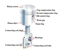
Components of Piston Assembly
Crankcase
The crankcase is that part of the engine block below the cylinders. It supports and
encloses the crankshaft and provides a reservoir for the lubricating oil.
• The crankcase holds all of the engine parts in alignment and supports the cylinders and
crankshaft
• It provides a place to mount the engine to the aircraft
• Constructed of aluminum alloy
• Divided into sections (radial)
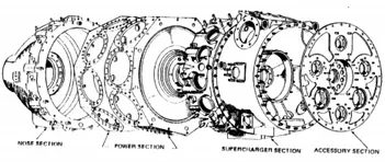
• Nose section - Houses prop shaft and bearings
• Power section - mount for cylinders
• Fuel induction section - intake tubes, blower, manifolds (supercharger)
• Accessory section - mounts for magnetos, pumps, generators (magnesium)
• Opposed crankcase
• Sections are not as distinct as in the radial and the crankcase splits from front
to rear instead of in radial sections
Crankshaft
• Constructed of chrome-nickel-molybdenum-steel
• Maybe one piece or as many as three separate pieces
• The crankshaft rotates within the crankcase and is supported by main bearing journals
• Crankshaft throws or crankpins are off-center and account for the reciprocating motion of
the pistons
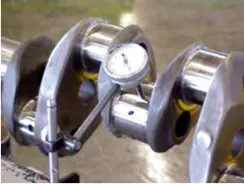
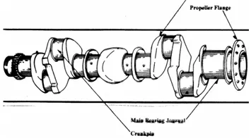
• Counterweights are used to reduce vibration but they are rigid
• Counterweights are used in piston engines because the power pulses and
movement of the pistons create large amounts of vibration
• Vibration shortens airframe and engine life and can lead to premature
component failure
• 2 Piece Crankshaft With Counterweights (Single
Throw, Single Cylinder)
Camshaft
• Used to open the valves for intake and exhaust
• Must be mechanically coupled to the crankshaft for timing purposes (gears,
belts, chains)
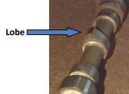
• The camshaft consists of bearing journals and lobes spaced along the shaft
• Each lobe is positioned to open and close a valve at a specific time
Piston
• Constructed of aluminum alloy
• Parts include top, ring grooves, ring lands, skirt, and piston pin boss
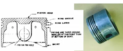
• Cooling fins on the bottom help the oil carry heat away from the piston top
Piston Pin
The piston is attached to the connecting rod by the piston pin (wrist pin).
• Piston pins are made of alloy steel with a precision finish
• They are lubricated by splash from the crankcase or by
pressure passages bored in the connecting rods
• The pin is retained in the piston with clips or plugs to prevent cylinder wall scoring
Piston Pin
• Three methods are commonly used for fastening a piston pin to the piston and the
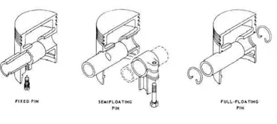
Connecting Rod Assembly
● The link between the crankshaft and the piston
● Normally steel but some low powered engines use aluminum to save weight
● Types include : Plain Rod
● Fork and blade rod
● Master and articulated

Motion study setup of Ic engine Piston assembly
1.Once the assembly of piston parts mated, enable the Solidworks motion from Solidworks add-in bard

2.Then enable the motion study from bottom left tab.
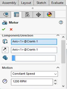
3.Add motor to rotate in clockwise direction about 1200rpm.
4.Set motion analysis frame settings to 7200 to capture each crank angle and its displacement.
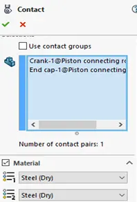
5.Make contacts between crank and endcap, gudgeon pin and crankshaft, gudgeon pin and piston body,also apply material to steel (dry)

6. Run simulation by click the calculate button.

RESULTS:
1.It shown an uniform distribution of curve for linear displacement of piston through out duration of time.
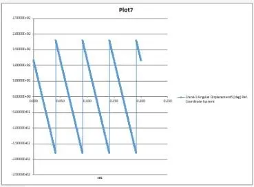
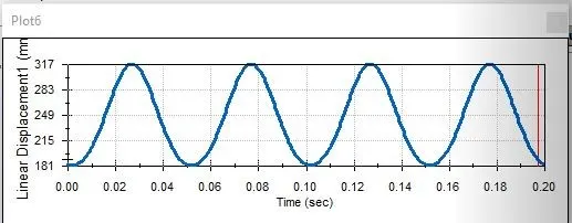
1.Crank angle plotted from excel 2.Linear displacement of piston
2.The crank angle which shown equal in positive and negative direction at all instances
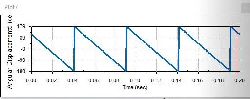
3.Angular displacement of crankshaft
3.The crankshaft displaces angularly reached a point of 120 for the duration of 0.2sec
Conclusion: Hence to conclude, the piston assembly was assembled and done motion study and acquired relevant plots
- Anil PailaMULTIBODY DYNAMICS Piston Connecting Rod assembly https://www.youtube.com/watch?v=QlorczwK55E OTHER PROJECTS LINKS Geneva Mechanism https://www.youtube.com/watch?v=tWeMgLCYHfI Ic Engine Vave Train https://www.youtube.com/watch?v=7z7bivr-UEc Machine Vice Assembly https://www.youtube.com/watch?v=iCxi0G2_Cso Planetary gear motion https://www.youtube.com/watch?v=ssyLwPO50qU