MBD Simulation on a Piston Assembly
SIMULATION ON A PISTON ASSEMBLY
AIM
Model all the parts and then assemble them in SolidWorks. The motion analysis is going to be carried out in three different conditions,
Sl.No |
Wrist Pin Offset ` |
Crank Speed (Rpm) |
1 |
"0" mm |
2000 |
2 |
10 mm Positive |
2000 |
3 |
10 mm Negative |
2000 |
Wrist Pin Offset - The position of the wrist pin is going to be varied as followed. But the center of the axis of the piston head and the crank are coincident to each other (i.e) They are on the same plane in all the three cases.
"0" mm Offset - Run a simulation
10 mm Positive Offset - If the crank rotation is in the Clockwise direction.
10 mm Negative Offset - If the crank rotation is in the Clockwise direction.
Obtain the Linear displacement of the Piston Head in all the three cases. Then export the graphs into Excel. Then Superimpose all the three graphs into a single graph.
INTRODUCTION
The assembly of the piston, connecting rod and crankshaft in an engine behaves like a mechanism during the working of the engine. The weight of the Cast Iron piston is preventing the engine from operating at a higher speed. The dimensions of the engine piston, connecting rod and crankshaft are calculated theoretically. Both structural analysis and dynamic analysis are to be done for the assembly. As the piston and the other components of the assembly work under high temperatures,thermal analysis is also done
. 
Theory
piston
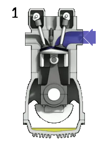
This 3D model shows all major components associated with a typical piston assembly, these include:
Piston Head
Piston Crow
Piston Rings
Piston Ring Grooves
Piston Skirt
Gudgeon Pin
Connecting Rod (Con Rod)
Connecting Rod Bearing (Con Rod)
Cap
Piston is a cylindrical plug which is used for moving up and down the cylinder according to the position of the crankshaft in its rotation .piston as multiple uses and function .in the case of four stroke engine the piston is pulled or pushed with the help of crankshaft while in the case of compression stroke,piston is pushed with the powerful explosion of mixture of air and fuel
Connecting rod
A connecting rod is an engine component that transfers motion from the piston to the crankshaft and functions as a lever arm. Connecting rods are commonly made from cast aluminum alloy and are designed to withstand dynamic stresses from combustion and piston movement. The small end of the connecting rod connects to the piston with a piston pin. The piston pin ,wrist pin provides a pivot point between the piston and connecting rod. Spring clips, or piston pin locks, are used to hold the piston pin in place.
Gudgeon pin
The gudgeon-pin (piston pin) wrist pin connects the piston and connecting-rod. It is supported in holes
bored in the piston at right angles to the piston axis at about mid-height position, and the centre
portion of the gudgeon-pin passes through the connecting-rod small-end eye. This hinged joint
transfers directly the gas thrust from the piston to the connecting-rod and allows the rod to pivot
relative to the cylinder axis with an oscillating motion.
crankshaft
The crankshaft is a moving part of the internal combustion engine It’s main function is to transform the linear motion of the piston into rotational motion. The pistons are connected to the crankshaft through the connecting rods. The crankshaft is mounted within the engine block.
Objectives
To create a 3D model.and study the motion analysis using solidworks
And used to find linear displacement of piston at different offset of wrist pin
Results and plots
From the plots
We obtain that linear displacement of piston is slightly more without offset of wrist pin
Superimpose shows slight increase in linear displacement from negative to positive offset
TDC =TDC and BDC=BDC of piston in zero offset
for non zero offset nither equality holds
compression ratio increases with offset
Conclusion
changes in the piston locaton and volume may differ but even though difference are small accounting wirst pin are important because offset can cause significant effects as high rate of heat release
so including the offset in simulation ,better the model represent the engine ,better the result will be