MBD Simulation on a Piston Assembly using Solidworks
OBJECTIVE- To model all the parts of the piston assembly and then assemble them to run a multibody dynamics simulation on that with different cases.
THEORY- An internal combustion engine is a heat engine where the combustion of a fuel occurs with an oxidizer (usually air) in a combustion chamber that is an integral part of the working fluid flow circuit. In an internal combustion engine, the expansion of the high-temperature and high-pressure gases produced by combustion applies direct force to some component of the engine. The force is applied typically to piston , turbine blades, rotor or a nozzel This force moves the component over a distance, transforming Chemical energy into useful mechanical energy.
Fig.2 Piston Assembly
The parts are as follows :
- Piston Head
- Gudgeon Pin (Wrist pin)
- Connecting rod
- End Cap
- Crank
Piston Head: piston is a component of reciprocating engines, reciprocating pumps, gas compressors and pneumatic cylinders, among other similar mechanisms. It is the moving component that is contained by a cylinder and is made gas-tight by piston rings. In an engine, its purpose is to transfer force from expanding gas in the cylinder to the crankshaft via a piston rod and/or connecting rod.
Gudgeon Pin (Wrist pin)- In an internal combustion engine, the gudgeon pin(wrist pin) connects the piston to the connecting rod and provides a bearing for the connecting rod to pivot upon as the piston moves.
Connecting rod- A connecting rod is a rigid member which connects a piston to a crank or crankshaft in a reciprocating engine.
End Cap- The End Cap is used to fix the connecting rod with the crankshaft.
Crank- A Crank or crankshaft is a mechanical part able to perform the conversion between reciprocating motion and rotation motion. It translates reciprocating motion of the piston into rotation motion. Whereas in the reciprocating compressor, it converts rotational motion into reciprocating motion.
Creating all the parts of Piston Assembly with 2D diagram
1) Piston Head
2) Gudgeon Pin (Wrist pin)-
3) Connecting rod-
4) End Cap
5) Crank-
Piston Assembly- Now opening the new file as assembly and inserting all the parts one by one and providing them contraints/mates to make th complete assembly. Mates being used were shown in figure-
Piston motion analysis:
Piston motion analysis is the study of the reciprocating motion of the piston in the cylinder and the motion of the assembly attached i.e. connecting rod, end cap, crankshaft & wrist pin. First of all for the assembly of a connecting rod, crankshaft, end cap, wrist pin and piston itself, we will prepare the geometric model of all the necessary components.
Negative 10mm Offset
Zero Offset
Positive 10mm Offset
In the Motion study the following steps are performed.
- Select motion analysis in the drop-down menu.
- Motor is given to crank with the speed 2000 RPM clockwise.
- Frames per second are given as 12000 with precise contact
- There are total 4 contact pairs as connecting rod and crank, end cap and crank, connecting rod and piston head & Piston and Wrist pin
- Gravity in the Y direction.
- And now for all the motion analysis done by clicking on calculation and setting the time key 0.5sec to get the results.
- Now after the calculation obtain the plot for the linear displacement of the piston w.r.t time.
The motion analysis is going to be carried out in three different conditions
|
S.No |
Wrist Pin Offset (mm) |
Crank speed (RPM) |
|
1. |
0 mm |
2000 |
|
2. |
10mm Positive |
2000 |
|
3. |
10mm Negative |
2000 |
RESUlTS & PLOTS:
1) Zero Offset
2) Positive 10mm Offset
3) Negative 10mm Offset
4) Superimposed Graph
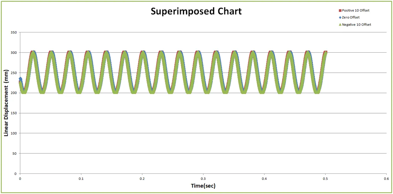
As observed form the above graphs the linear displacement remains almost same in all the three cases.
1) The linear displacement at 0 offset : 302.432825609819
2) The linear displacement at 10mm positive offset: 302.308213379358
3) The linear displacement at 10mm negative offset: 302.304495861784
CONCLUSION
1) We see that Stroke length decreases as we introduce offset to any direction. Maximum of stroke length can be seen on the "omm" offset case. Giving offset to the wrist pin decreases the distance travelled by the piston more in positive offset than negative offset. This reduces the piston slapping and also reduces the friction loss thus increasing power output of the engine.
2) Engine displacement is the multiplication of stroke length to the cross-sectional area of the cylinder as the stroke length decreases on introducing offset, the engine displacement also got decreased. From the plots obtained, we can see that Linear Displacement increases as we move from negative wrist pin offset to positive wrist pin offset i.e. the magnitude of the Linear displacement increases.
3) Generally, bigger-displacement engines develop more torque, but small engines can spin faster, which increases their horsepower output.
4) Having an offset pin relieves the stress that is caused in the rod when it reaches the top or bottom dead center.
5) When the wrist pin is in the center that is "0mm" offset, the piston reaches the top dead center (TDC) and bottom dead center (BDC) by making the connecting rod straight up and down which place a huge load on the connecting rod. The crank has to rotate past TDC or BDC in order to get the piston moving again which takes a lot of power and RPMs from the engine.