MBD Simulation on a Piston Assembly
Multibody dynamic analysis of a piston assembly in an IC engine
Aim:
The main of this project is to make an analysis of the piston displacement of an IC engine for three different positions (no offset, positive 10 mm offset, negative 10 mm offset) of the wrist pin with respect to the crankshaft axis and to plot them against time. Solidworks is the software used.
Geometric modelling of the various parts
The piston assembly of an IC engine consists of piston, crankshaft, connecting rod, wrist pin or gudgeon pin. These components are designed using solidworks.
Piston
The piston is the component that transfers the power obtained from the combustion to the crankshaft. The piston is placed inside the cylinder. The piston oscillates linearly within the cylinder.
Connecting rod
The connecting rod connects the piston with the crankshaft. The wrist pin is used to link the connecting rod to the piston on the top side. And on the lower side, the end cap secures the connecting rod with the crankshaft. The connecting rod has the most complex motion in this assembly.
The connecting rod is fastened with bolts to the end cap.
Gudgeon pin End cap
Crankshaft
The crankshaft converts the linear motion of the piston to a rotary motion.
These components are assembled by providing necessary constrains and are prepared for the motion study. A motor is introduced at the crankshaft at a speed of 2000 rpm in the clockwise direction. Solid body contacts are established between the bodies. To obtain the accurate value of displacement, 12000 frames per second are used to capture the data.
Motion study setup
Results:
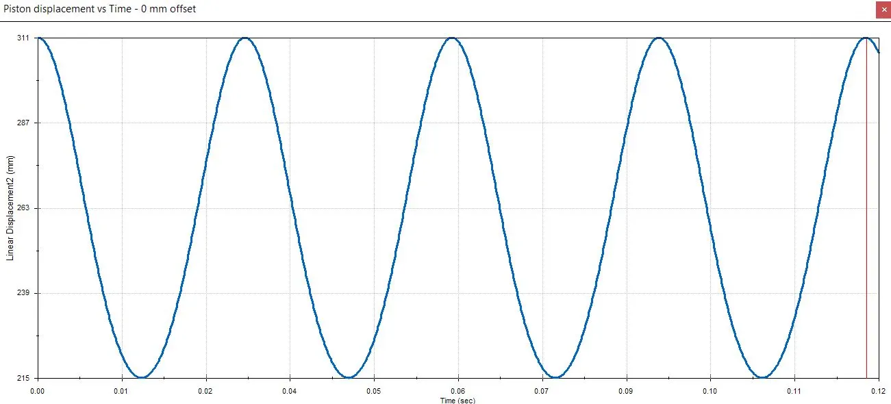
1. No offset
In this case there is no offset between the wrist pin axis and the crankshaft axis.
Displacement vs Time - 0 mm offset
2. 10 mm positive offset
In this case, the wrist pin axis is 10 mm to the left of the crank pin axis.
Displacement vs Time - 10 mm positive offset
3. 10 mm negative offset
In this case, the wrist pin axis is 10 mm to the right of the crank pin axis.
Displacement vs Time - 10 mm negative offset
These graphs are exported to excel so as to superimpose them to get a better comparison between the various cases.
Conclusion:
Thus, the multibody study was conducted on a piston assembly was conducted and the results for the various cases was plotted and compared. By observing the displacement data closely, it can be seen that the displacements of the cases (no offset, positive offset and negative offset) are increasing gradually.