MBD Simulation on a Piston Assembly
Aim:
To create all the model and assemble them in solidworks and do a motion study on it.
Solution:
Engine:
An engine or motor is a machine designed to convert one form of energy into mechanical energy.heat engine, like the internal combustion engine, burn a fuel to create heat which is then used to do work. electric motors convert electrical energy into mechanical motion, pneumatic motors use compressor motor, and clockwise motors in wind up toys use elastic energy. In biological systems, molecular motors, like myosins in muscles, use chemical energy to create forces and ultimately motion.
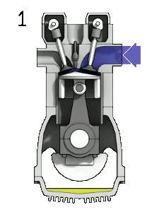
All the part modelling are shown below
Step1: Piston
First I have selected the right plane all the assembly are done in right plane, then starting sketch with line command and create horizontal and vertical line and also by using three point arc create an arc and connect it with the lines then by using a short cut 's' and in that select smart dimensions and done dimensions based on video and after completing the sketch, in modelling select revolve bose and select the sketch and select the center axis and click ok.
Secondly i have made sketch on front plan again and create a circle and constrained it based on dimensions and select the sketch and do extrude cut on it,then select the front plan and draw a three point arc and close the arc by a line and make it dimensionally constrained and again go to extrude cut by selecting the sketch and complete the part, then by selecting the filet option and round the corner which are seem to be sharp, and save it as piston.
Step2: Connectind Rod
First I have selected the Right plane and started sketching first create a circle and make it dimensionally constrained and also create a outside offset and make that to dimensionally constrained and also create another circle with a distance which was given video in the course and also make same with those circles and also make them dimensionally constrained and then create a line that connects circle and mirror it and make it dimensionally constrained and create a offset by using power trim option trim the unwanted lines from the sketch and make the sketch complete and move to modelling and select extrude bose and select the sketch and give the dimensions based on the lecture video.
Secondly create a sketch at the bottom base and create a circle at the edge by selecting the center point of line to make the center of a circle and make it dimensionally constrained and mirror it to the other bottom end after this select that sketch and extrude it as per the dimensions given in the lecture video after that select the same bottom and create one more circle at the same point where the previous circle is created and make it dimensionally constrained and now extrude cut , then select the filet option and make the corners as rounded one and save it as connecting rod.
Step3: Connecting rod cap
First I have selected the right plane and started sketching frirst create a circle and make it dimensionally constarined and create an offset from the circle and also make it dimensionally constrained also create a circle with the center of the circle and trin the unwanted lines and make the sketch fully constrained then by selecting the extruded bose create the main part of cap and selecting the top face and create the circle as done in the connecting rod make it as same as possible and make the sharp corners to rounded corners by using filet and then save it as cap.
Step4: Pin
I have selected the right plane and start sketching first create a circle as per dimensions given in lecture video and offset the circle outside the circle and make it fully constrained and after sketching by using extrudede bose, extrude those sketch as like a cylinder after this top and bottom edges are rounded with a small radius by filet and save it as pin.
Step5: Crank shaft
I have selected the right plan and start sketching first create a three point arc at the top and create one more at the bottom and connects the edges of the three point arc with line and make them fully dimensionally constrained and after this by using extrude bose, extrude the sketch with the dimensions as given in the lecture video, then in the one face i started sketching and create a circle and make it constrained and extrude it as per the dimensions and in one other face and create a three point arc and join the edges with line and make them dimensionally constrained and also create one more three point arc and make what i have done in the previous part and by extruded cut cut the section and in the other face create a circle and extrude it make them mirror in the other face of the plane and save the part as crank shaft.
[note: all the parts are uploaded in drive and their link is given below:
https://drive.google.com/drive/folders/135QugXLtEcSQO8uDn4My3rsgvgwv_Ghz?usp=sharing ]
Assembly:
First add the crank shaft and make it in the float condition and select the center line make the center line show option enabled and select the top plane and make coincedent, then select the right plan of the assembly and the right plan of part and make coincedent and the front plan and front plan coincident of part and assembly and then import then next components and make them fully constrained based on the lecture video.
After completing the assembly first check the solidworks ads on that select the solid works mbd or motion study after that select the motion study in the tab and give motor force to the one face of the crank shaft and then by using contact and select the contact and select crank shaft as first component and select the components as second component and set the frames per second to 7200 and set the timer to 2 sec and set the gravity to y axis and start calculation, during calculation a video is recorded and uploaded in youtube and the link is made available. After this select the graph and find the displacement force and the graph is made available.
Displacement force of piston without any offset:
This plot is for displacement of piston this has been done for the time and the displacement of the piston.
Then after this the piston should be offseted with a distance of 10mm and the center of the crank shaft and the the piston are coincident and again do the same process as done in the previous step and graph obtained is shown below,
Displacement force of piston with 10mm offset in positive direction :
This plot is for displacement of piston this has been done for the time and the displacement of the piston.
Then after this the piston should be offseted with a distance of 10mm and the center of the crank shaft and the the piston are coincident and again do the same process as done in the previous step and graph obtained is shown below,
Displacement force of piston with 10mm offset in negative direction :
This plot is for displacement of piston this has been done for the time and the displacement of the piston.
the assembled part window is shown below
Youtube link for all the three assembly:
Engine with out offset: https://youtu.be/t1NKErqLBes
Engine with out offset: https://youtu.be/lS11gJWWbnU
Engine piston with offset +10:https://youtu.be/JBg6CeI6DvE
Engine piston with offset +10:https://youtu.be/jFfr9E2Nq8o
Engine Assembly with -10 offset:https://youtu.be/tN17ZQB8dKs
Engine Assembly with -10 offset:https://youtu.be/QVLhI2n_DOQ
there are two videos for each assembly one is by saving the video after completing the calculation and other recorded using camtasia while calculation.
Result:
Finally the all the assemblys are made and Motion study for all the assembly has been done and displacement graph for pistion at three different position has been done they are discussed above.