MBD Simulation on a Piston Assembly
PISTON KINEMATICS
Kinematic analysis of the ICE piston. Automotive industry deals with reciprocating engines, in which the piston has a linear motion within the cylinder. The crank mechanism transforms the linear movement of the piston into rotational movement of the crankshaft.
OBJECTIVE: To perform the motion analysis for the piston assembly for the following conditions:
|
Wrist Pin Offset |
Crank Speed (RPM) |
|
0 mm |
2000 |
|
10 mm Positive |
2000 |
|
10 mm Negative |
2000 |
PROCEDURE
3D files (parts and assemblies) with their significance
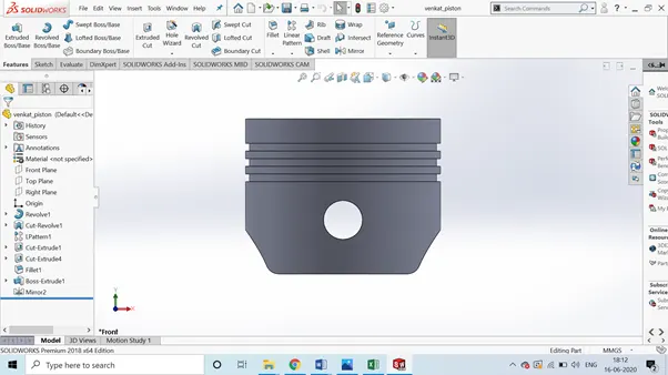
PISTON HEAD:
its purpose is to transfer force from expanding gas in the cylinder to the crankshaft via and/or connecting rod
CONNECTING ROD:
A connecting rod, also called a con rod, is the part of a piston engine which connects the piston to the crankshaft. Together with the crank, the connecting rod converts the reciprocating motion of the piston into the rotation of the crankshaft.
END CAP: The big end of the connecting rod connects to the crankpin journal to provide a pivot point on the crankshaft. A rod cap is the removable section of a two-piece connecting rod that provides a bearing surface for the crankpin journal. Here the end cap is been sketched in front plane and been extruded to get the end cap part.
GUDGEON PIN:
In internal combustion engines, the gudgeon pin connects the piston to the connecting rod
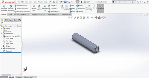
CRANK
Crank is used to transform the back-and-forth motion of the pistons into rotary motion
ASSEMBLY
MOTION ANALYSIS
Wrist Pin Offset - The position of the wrist pin is going to be varied as followed. But the centre of the axis of the piston head and the crank are coincident to each other (i.e.) they are on the same plane in all the three cases.
ZERO offset
Linear displacement reaches 330m/s max
NEGATIVE OFFSET
Linear displacement reaches maximum of 310m/s
POSITIVE OFFSET
Almost the same range is attained
SUPERIMPOSED PLOTS
https://drive.google.com/drive/folders/1mN7mczCaSkHwPBsRr9FYk0GzJDGTQmoH?usp=sharingThe linear displacement is almost the same the deviation is due to varying starting point
RESULT:
Hence the plots are obtained for all the 3 conditions using motion analysis
OBSERVATION:
During 0 offset the stress concentration is more
Positive/Negative offset relieves the stress in connecting rod
https://www.youtube.com/watch?v=QGjafZgIF-s&feature=youtu.be