MATLAB PROGRAM FOR AN OTTO CYCLE
AIM:
To write a Matlab program that can solve the Otto cycle and make plots for it and to calculate the Thermal efficiency of an Otto cycle.
THEORY:
AIR STANDARD CYCLE:
- A cycle is defined as the series of operations or processes performed on a system so that the system attains its original state.
- The cycle which uses air as the working fluid is known as the Gas power Cycle.
- In the Gas power cycle, the air in the cylinder may be subjected to a series of operations that cause the air to attain its original position.
- some of the assumptions made in the analysis of gas power cycle include:
- The working medium has constant specific heats.
- The working medium does not undergo any chemical change throughout the cycle.
- The compression and expansion processes are reversible and adiabatic.ie., there is no loss or gain of entropy.
OTTO CYCLE:
- This cycle which was introduced by Dr.A.N.Otto, a german scientist is called the Otto cycle. Nowadays, petrol and gas engines follow this cycle.
- This cycle consist of the following four processes are:
- Two reversible adiabatic or Isentropic process
- Two constant Volume process.
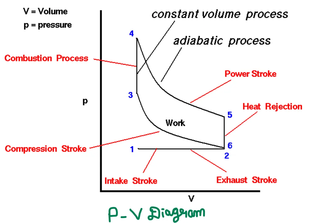
- Stage-1 is the beginning of the intake stroke of the engine. In this stage, the pressure is at atmospheric and the gas volume is at a minimum.
- Between stage-1 and stage-2 the piston is pulled out of the cylinder with the intake valve open.
- The pressure remains constant and the gas volume increases as fuel/air mixture are drawn into the cylinder.
- Stage-2 begins the compression stroke of the engine with the closing of the intake valve.
- Between stage-2 and stage -3 the piston moves back into the cylinder, the gas volume decreases, and the pressure increases because work is done on the gas by the piston.
- stage-3 is the beginning of the combustion of the fuel/air mixture. The combustion occurs very quickly and volume remains constant.
- Heat is released during combustion which increases both the temperature and the pressure, according to the equation of the state.
- Stage-4 begins the power stroke of the engine. Between stage-4 and stage-5, the piston is driven towards the crankshaft, the volume is increased and the pressure falls as work is done by the gas on the piston.
- At stage-5 the exhaust valve is opened and the residual heat in the gas is exchanged with the surroundings. The volume remains constant and the pressure adjust back to atmospheric conditions.
- Stage-6begins the exhaust stroke of the engine during which the piston moves back into the cylinder, the volume decreases and the pressure remains constant. At the end of the exhaust stroke, conditions have returned to stage 1 and the process repeats itself.
FORMULAS USED IN OTTO CYCLE:
The formulas which are used in the otto cycle includes:
Swept Volume:
- The Swept Volume is the volume of air displaced by the piston diameter in one full stroke from BDC to TDC.
Swept Volume=(`pi`/4)*bore^2*stroke.
where,
Bore=diameter of the cylinder.
Stroke=length of the piston.
Clearance Volume:
When the piston is at TDC, the space above the piston in the combustion chamber. The volume of this space is known as clearance volume. Due to the irregular shape of the combustion chamber, the clearance volume is calculated by filling the combustion chamber with the measured amount of fluid while the piston is at TDC.
Clearance volume=swept volume/r-1
where,
r---Compression ratio.
Total Volume of the cylinder:
The total volume of the cylinder is the summation of the swept volume of the piston and the clearance volume.
Total Volume =Swept Volume + Clearance Volume.
Adiabatic Process:
An Adiabatic process is defined as, The thermodynamic process in which there is no exchange of heat from the system to its surrounding neither during compression or expansion. Following is the adiabatic process equation:
PV^`gamma`=constant
where,
P is the pressure of the system
V is the volume of the system
gamma is the adiabatic index and is defined as the ratio of heat capacity at constant pressure Cp to heat capacity at constant volume Cv.
Combined Gas Law:
The Combined gas law is the law that combines Charles's law, Gay-Lussac's law, and Boyle's law. It's an amalgamation of the three previously discovered laws. These laws relate one thermodynamic variable to another holding everything else constant. The interdependence of these variables represents combined gas law which states that the ratio between the product of pressure-volume and temperature of a system remains constant.
k=PV/T
where,
P=Pressure
T=Temperature in kelvin
V=Volume
k=constant
VOLUME TRACE INSIDE THE CYLINDER:
The volume change inside the combustion chamber can be calculated by using the formula:
V/Vc=1+1/2(rc-1)[R+1-costheta-(R^2-sin^2theta)^1/2]
where,
vc--clearance volume
rc---compression ratio
R--The ratio of connecting rod to the crankpin radius.
crankpin radius (a)=stroke/2
THERMAL EFFICIENCY:
The Thermal efficiency for an otto cycle can be calculated by using the formula:
Thermal efficiency=[1-1/cr^(gamma-1)]*100
MATLAB PROGRAM:
clear all
close all
clc

%inputs

gamma=1.4
t3=2300

%state variables

p1=101325
t1=500

%Engine geometric parameters

bore=0.1;
stroke=0.1;
con_rod=0.15;
cr=12;

%Calculating the swept volume and the clearance volume

v_swept=(pi/4)*bore^2*stroke;
v_clearance=v_swept/(cr-1);
v1=v_swept+v_clearance;
v2=v_clearance

%state variables at state point2
%p2v2^gamma=p1v1^gamma

p2=p1*cr^gamma;

%p1v1/t1=p2v2/t2

t2=p2*v2*t1/(p1*v1);

constant_c=p1*v1^gamma;
v_compression=kinematics_1(bore,stroke,con_rod,cr,180,0);
p_compression=constant_c./v_compression.^gamma;

%state variables at state point 3

v3=v2

%p3v3/t3=p2v2/t2

p3=p2*t3/t2


constant_c=p3*v3^gamma;
v_expansion=kinematics_1(bore,stroke,con_rod,cr,0,180);
p_expansion=constant_c./v_expansion.^gamma;

%state variables at state point 4

v4=v1

%p3v3^gamma=p4v4^gamma

p4=p3*(v3/v4)^gamma

thermal_efficiency=(1-1/cr^(gamma-1))*100

figure(1)
hold on
plot(v1,p1,'*','color','r')
plot(v_compression,p_compression)
plot(v2,p2,'*','color','r')
plot(v3,p3,'*','color','r')
plot(v_expansion,p_expansion)
plot(v4,p4,'*','color','r')
plot([v2 v3],[p2 p3])
plot([v4 v1],[p4 p1])
xlabel('volume');
ylabel('pressure');
title('P-V diagram')
- The program starts with the command clear all, close all, and clc in order to clear all the data stored in the workspace, plot, and command window.
- Then the given input values are entered such as gamma,t3,p1, and t1. Here tn represents the temperature values at state point 'n', similarly on represents the pressure value at state point n and vn represent volume at state points 'n'.
- The engine parameters are entered which includes bore diameter, stroke length, connecting rod length, and the compression ratio of the engine.
- The swept volume and Clearance volume is calculated by using the above formula.
- Similarly, Temperature, Pressure, and Volume are calculated at each state points 1,2,3&4.
- Every value of the crank angle function is defined by using another program.
Function code:
function [V]=kinematics_1(bore,stroke,con_rod,cr,start_crank,end_crank)


a=stroke/2;
R=con_rod/a;
v_s=(pi/4)*bore^2*stroke;
v_c=v_s/(cr-1);

theta=linspace(start_crank,end_crank,180);

term1=0.5*(cr-1);
term2=R+1-cosd(theta);
term3=(R^2-sind(theta).^2).^0.5;

V=(1+term1*(term2-term3)).*v_c
end- The function is defined by using the function syntax that accepts inputs such as bore, stroke,con_rod,start_crank,end_crank, and the output of this stored in [v].
- The formulas for swept volume and clearance volume is defined inside the function.
- The value of the crank angle theta is calculated for 180 values between starting crank angle and end crank angle with the help of linspace command.
- The volume inside the cylinder for every value of theta is calculated by using the above-mentioned formula.
- Then this volume trace is called in the main program and v_compression,p_compression,v_expansion,p_expansion is calculated with respect to the value of crank angle theta.
- Then the thermal efficiency is calculated by using the formula.
- All the state variable points are plotted and are connected appropriately and thus p-v diagram for the otto cycle is obtained.
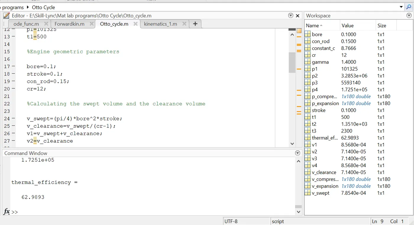
ERRORS FACED WHILE PROGRAMMING:
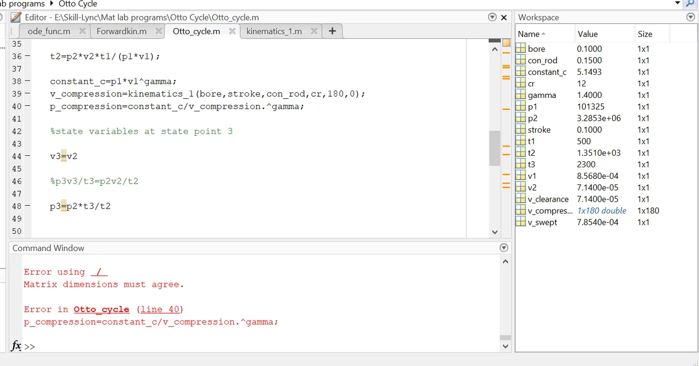
- Since v_compression is an array (it consist of 180 values) dot factor needs to implement. This error can be rectified by inserting a dot symbol in order to multiply it with every value.
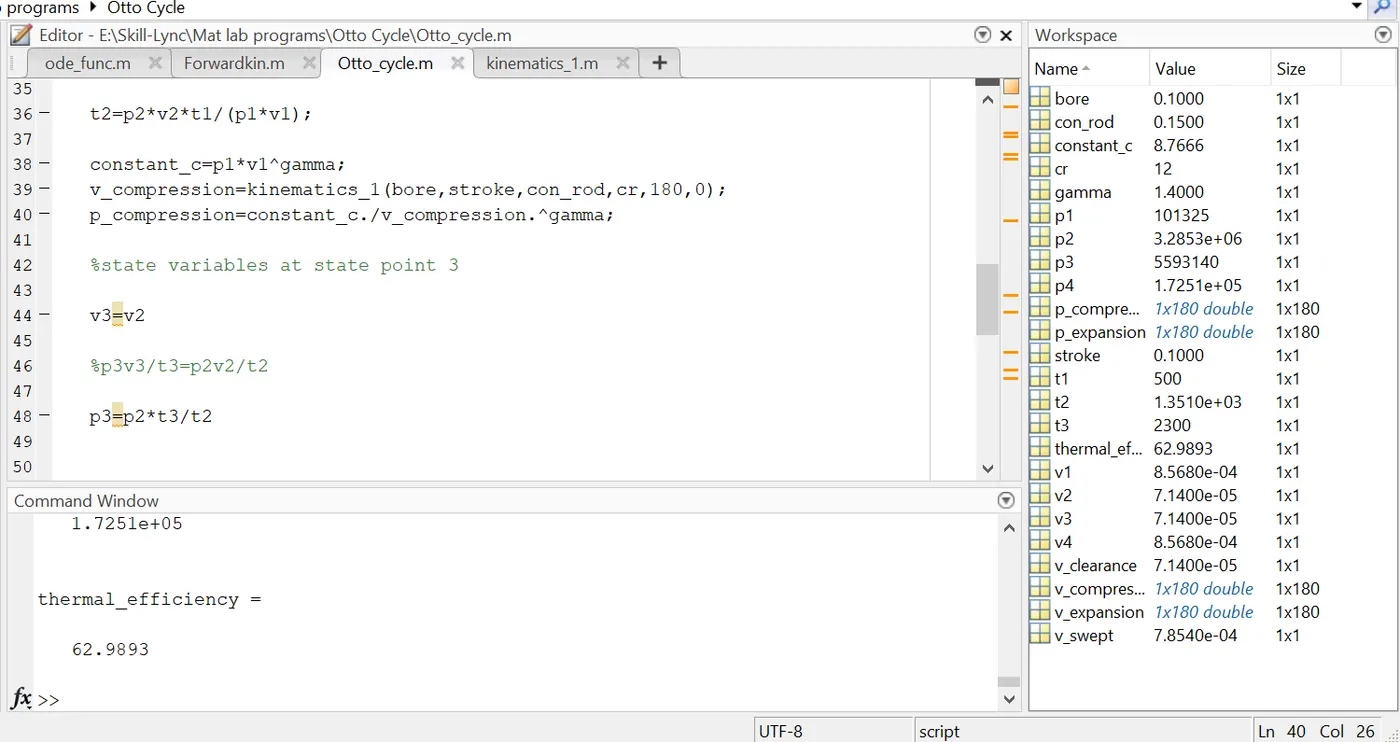
RESULT:
- The actual P-V diagram for an otto cycle is plotted and the temperature, pressure, and volume values at each state point are calculated.
- The thermal efficiency is also calculated with the help of the formula.
LEARNING OUTCOMES:
- Understand the actual volume changing process from stage points 2-3 and from 4-5.
- Understand how to connect two points using a curve.
- Understand how to define and call the function wherever it requires in the program.