Lead acid battery mathematical modelling
AIM: Lead Acid Battery mathematical modeling and comparing the effect of discharge rate on capacity.
INTRODUCTION:
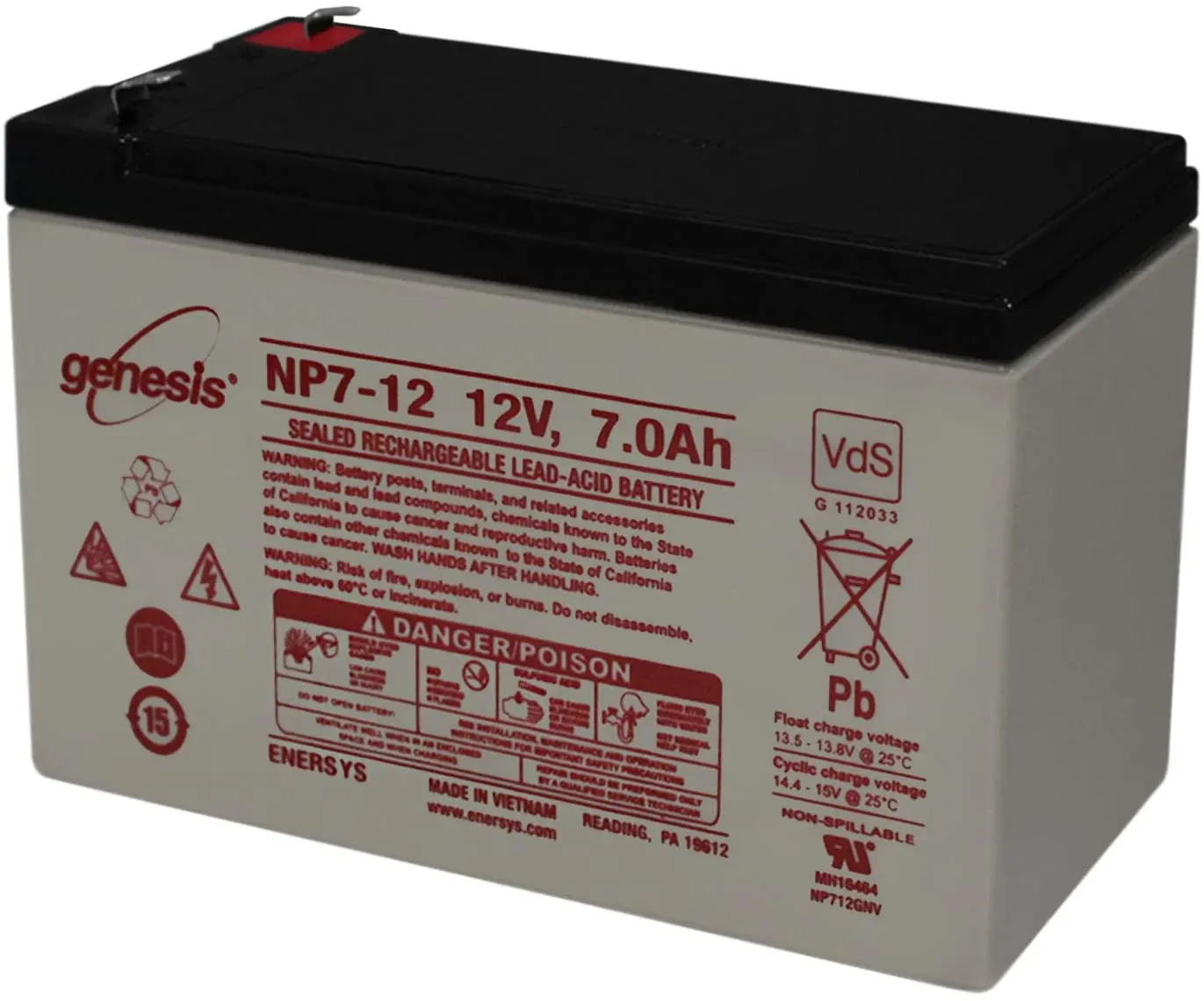
Lead-acid batteries are used in start-stop automotive systems and large-scale grid energy storage systems.
Lead-acid batteries use lead as anode material and lead dioxide as a cathode material. The electrolyte used is Sulfuric acid. AGM (Absorbed glass mat) is used as a separator.
The chemical reaction for a lead-acid battery is as follows,
`PbO_2 + Pb + H_2SO_4 iff 2PbSO_4 + 2H_2O`
Voltage for Pb-acid cell varies between 2.15 and 1.75 between completely charged and completely discharged(cut-off) state and can be expressed using the below equation,
`E=2.15-DOD⋅(2.15-1.75)"`
DEFINITIONS:
Open Circuit Voltage (E):
Open circuit voltage is a maximum theoretical voltage that an ideal battery can achieve. This voltage is not possible to achieve in actual conditions because of losses and internal resistance of the battery. OCV can be approximated by discharging the battery at a very low discharge rate i.e. around C/20.
SOC:
SOC represents the state of charge of the battery. SOC shows how much charge/energy is available in the battery at a given instant of time. SOC ranges from 0% to 100%
SOC value depends on the previous behavior (hysteresis) of the battery and can be calculated as bellow,
`SOC=SOC_(previous-time-step)-(1/Q)∫η(t)⋅i(t)dt"`
where,
Q = Capacity
`eta` = Coulombic efficiency or charge efficiency
DOD:
DOD represents the Depth of discharge of the battery. It shows the amount of energy removed from a battery at a given instant of time.
DOD = Charge removed/ Peukert's Capacity
also, DOD = 1- SOC
Discharge rate:
The discharge rate is the rate at which the current is drawn from the battery to the per hour rated current.
for example,
A battery discharged at 5 Amp current having a capacity of 5 Ah is said to have a discharge rate of C1
Peukert's law:
Peukert's law expresses the battery capacity with respect to the rate of discharge. The law states that the discharge capacity of the battery decreases with the increase in the rate of discharge current.
Peukert's coefficient is k. This constant has a value closer to 1 ( in this case 1.045). The coefficient k correlated the current at a given time.
Peukert's capacity = `Cp=I^kT`
where,
I = current
T = Time
Charge removed:
Charge removed is the amount of energy removed from the total stored energy in the battery. The amount of energy removed is higher than the actual amount of energy supplied to the system. The charge removed also depends on the behavior of the battery in an earlier time step.
`CR=CR_(earlier-time-step)+(I^k⋅dt)/3600`
Charge Supplied:
Charge supplied is the actual amount of energy or charge supplied to the system from the battery. The charge supplied is always less than the charge removed and depends on the earlier time step behavior.
`CS=CS_(earlier-time-step)+(I⋅dt)/3600"`
RESULTS:
Open circuit voltage (E) and Battery discharge voltage vs Depth of Discharge (DOD)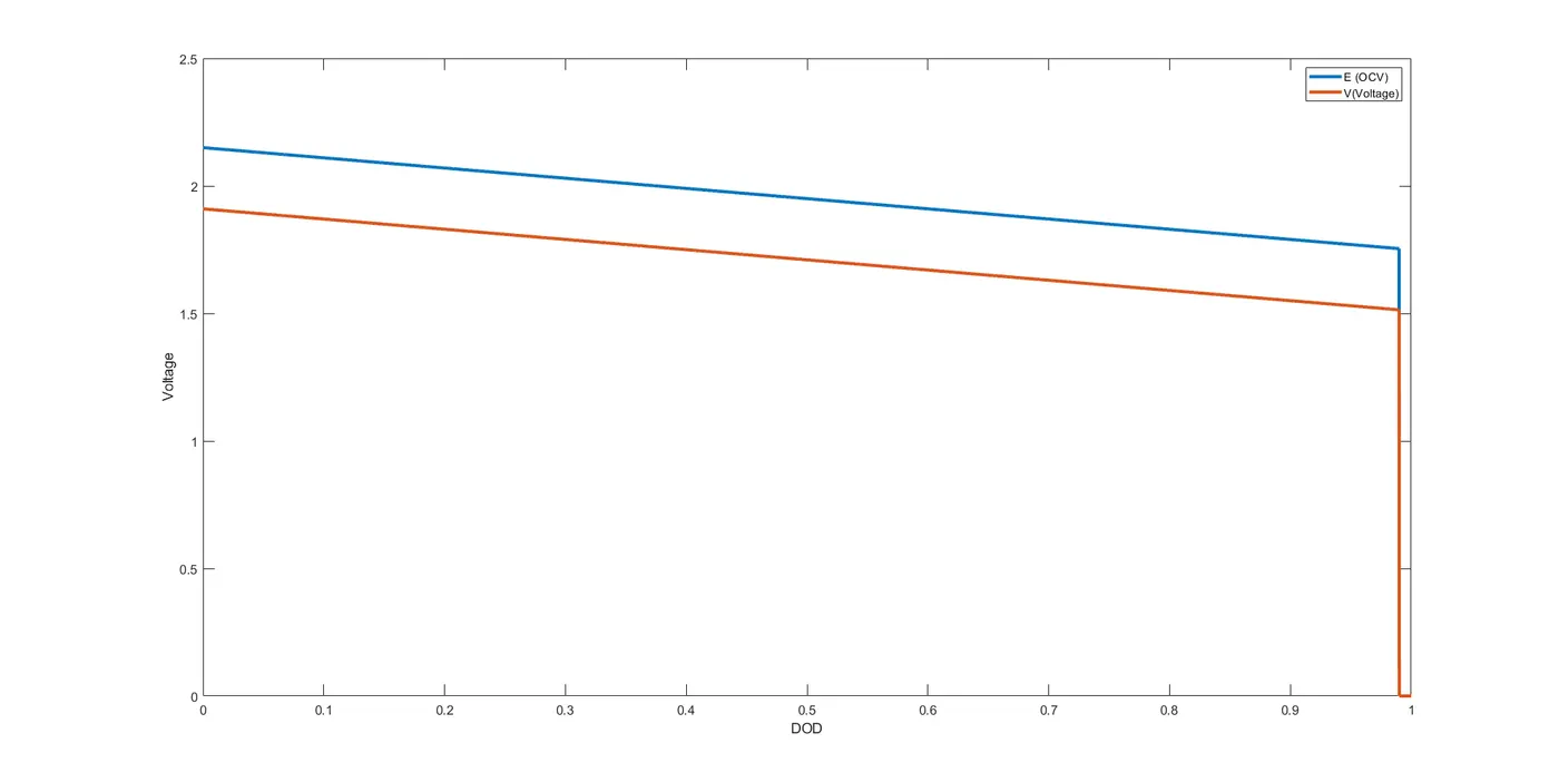
This plot shows the variation of Open circuit voltage and battery discharge voltage with respect to DOD. The difference between both the voltage is due to the internal resistance of the battery and other looses (temperature, chemistry, etc)
Open circuit voltage (E) and Battery discharge voltage vs Depth of Discharge (DOD) at different discharge rates
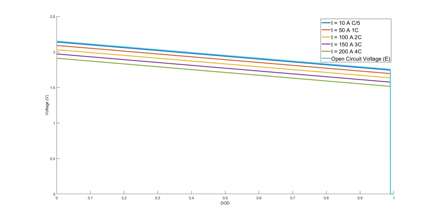
From this plot, it can be observed that as the discharge rate increases the discharge capacity of the battery decrease. The topmost line is the Open circuit voltage and is the maximum possible voltage that a battery can attain ideally. But in real life this is impossible and by decreasing the discharge rate a close value to OCV can be obtained.
Open circuit voltage (E) and Battery discharge voltage vs Charge Removed (CR)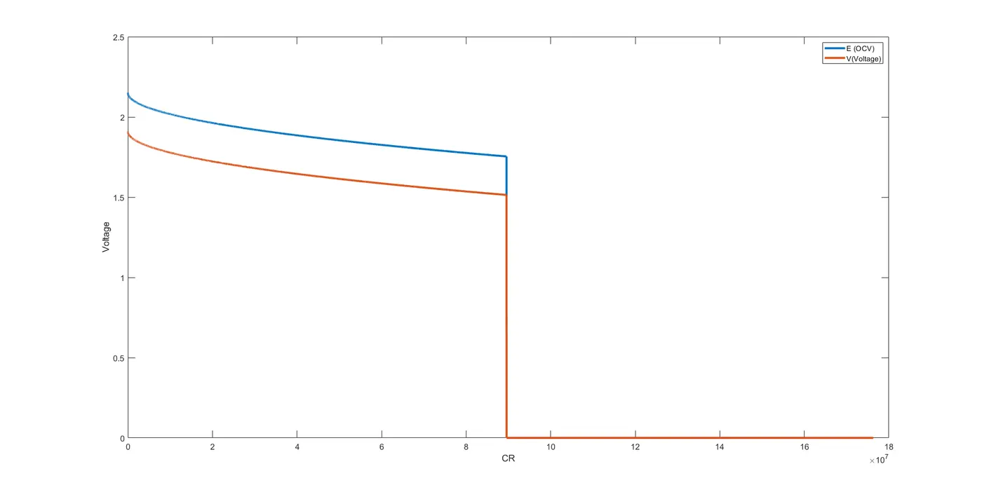
From the plot of voltage vs Charge removed (CR) and Voltage vs Charge supplied (CS), it can be seen that the charge removed is higher than the charge supplied to the system.
Open circuit voltage (E) and Battery discharge voltage vs Charge Supplied (CS)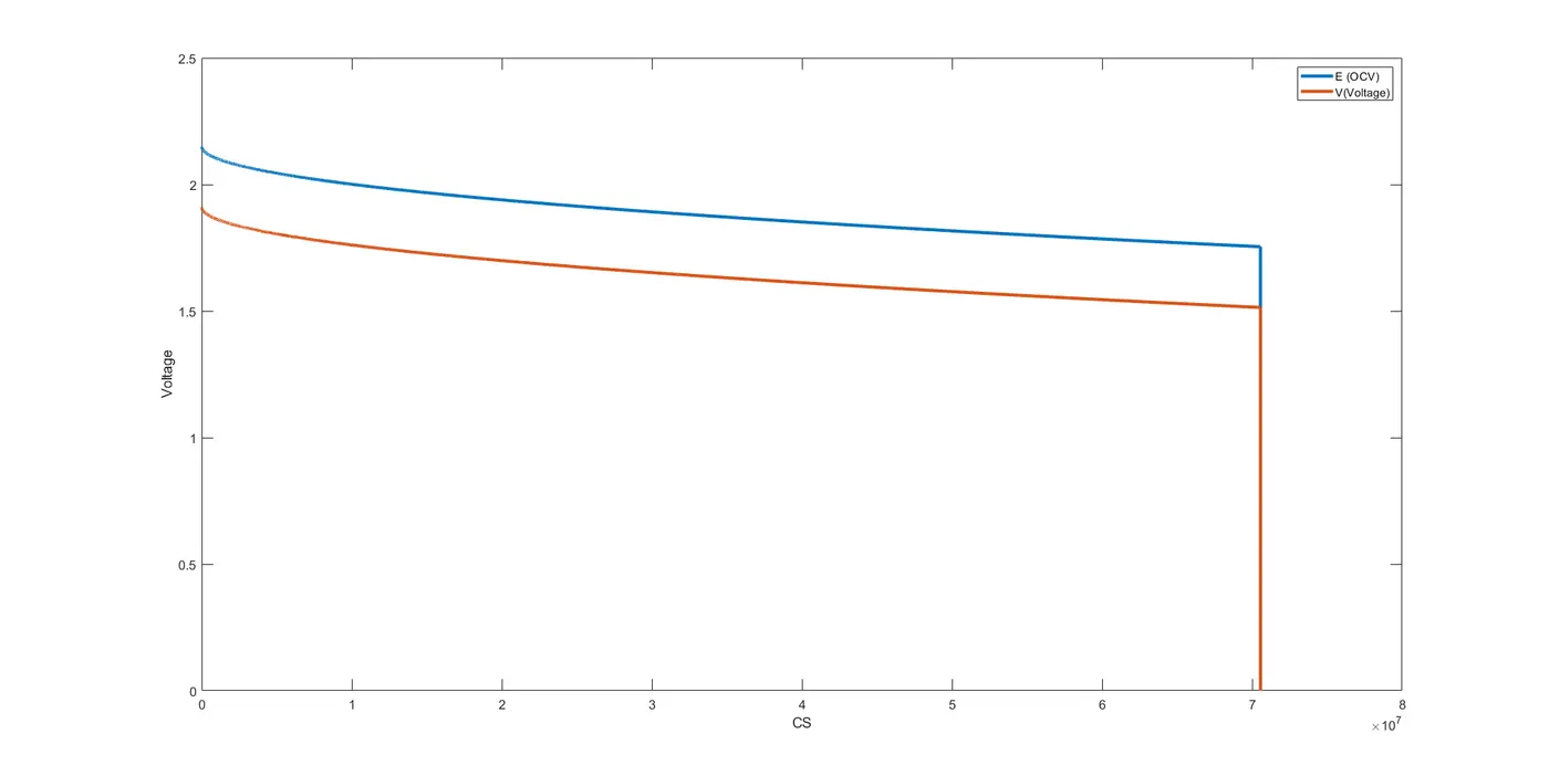
This plot shows the variation of OCV and battery voltage with respect to charge supplied.
MATLAB CODE:
clear all
close all
clc
%defining time steps in variable T
% total 10,001 time steps with each time step of 50 seconds
T = (0:50:500000);

CR  = zeros(1, length(T));
DOD = zeros(1, length(T));
V   = zeros(1, length(T));
CS  = zeros(1, length(T));
Cp  = zeros(1, length(T));
E   = zeros(1, length(T));
I   = [10,50,100,150,200]; % CURRENT IN AMPERES
nc  = 1; % number of cells
C   = 50; % 50 Ah
k   = 1.045; % .045 represents loss of capacity due to discharge
dT  = (T(2) - T (1))* ones(1, length(T)); % timestep
R_internal = (0.06/C)*nc;
E(1) = 2.15; %open circuit voltage
%V(1) = nc * (2.15 - I(i) * R_internal);

for i = 1:length(I)
    V(1) = nc * (2.15 - I(i) * R_internal);
%Define voltage equation for OCV
for n = 2:length(T)
    dT(n) = T(n)-T(1);
    Cp = (I(i)^k)*dT(n); %Peukert_capacity

    CR(n) = (CR(n-1) + (dT(n) * (I(i)^k))/3600);
    DOD(n) = (CR(n)) / Cp;

    E(n) = 2.15 - DOD(n) * ( 2.15 - 1.75);
    V(n) = E(n) - I(i)*R_internal;

    if DOD(n) > 0.99
        E(n) = 0;
        V(n) = 0;
    end

    if DOD(n) > 1
        DOD(n) = 1;
    end

    if E(n)>0
    CS(n) = CS(n-1) + ((I(i)*dT(n))/3600);
    else
        CS(n)= CS(n-1);
    end
end

figure(4);hold on

plot (DOD,V,'LineWidth',3)
ylabel('Voltage (V)','FontSize',18)
xlabel('DOD','FontSize',18)
set(gca,'FontSize',12)

end
plot (DOD, E,'LineWidth',3)
legend('I = 10 A C/5','I = 50 A 1C','I = 100 A 2C','I = 150 A 3C','I = 200 A 4C','Open Circuit Voltage (E)','FontSize',18)


figure(1)
plot( DOD, E,'LineWidth',3 )
hold on
plot( DOD , V,'LineWidth',3 )
legend('E (OCV)', 'V(Voltage)')
ylabel('Voltage')
xlabel('DOD')
set(gca,'FontSize',12)

figure(2)
plot( CR , E ,'LineWidth',3)
hold on
plot( CR , V ,'LineWidth',3)
legend('E (OCV)', 'V(Voltage)')
ylabel('Voltage')
xlabel('CR')
set(gca,'FontSize',12)

figure(3)
plot( CS , E,'LineWidth',3 )
hold on
plot( CS , V ,'LineWidth',3)
legend('E (OCV)', 'V(Voltage)')
ylabel('Voltage')
xlabel('CS')
set(gca,'FontSize',12)
EXPLANATION OF CODE:
Defining the time step:
10,001-time steps are defined with each time step of 50 seconds.
Pre-defining the variables for faster simulation
The variable CR, CS, DOD, V, Cp, E are predefined for improving the performance of the simulation.
I is the discharge current and is taken as 10,50,100,150,200. This are the different discharge rates as C/5, 1C, 2C,3C, and 4C.
Similarly, other constant variables are defined before the start of the loops.
1st for loop is used to calculate run the inner commands for each value of discharge current I
2nd for loop is the time loop and it calculates values of CR, CS, E, V, DOD, and SOC and repeats itself till the end of the defined time steps.
if loops are used such that the voltage and OCV will drop to ) when DOD reaches any value above 0.99 and further the value of DOD is considered as 1 ( i.e the battery is assumed to be completely discharged)
Further the results are plotted using the plot command.