Introduction to REVIT concepts
INTRODUCTION TO REVIT CONCEPTS
AIM -
- TO STUDY THE INTRODUCTION TO REVIT CONCEPT
- THE TARGET OF THESE PROJECTS IS TO SOLVE ALL THE TASKS GIVEN.
INTRODUCTION -
Autodesk Revit is a building information modeling software tool for architects, landscape architects, structural engineers, mechanical, electrical, and plumbing (MEP) engineers, designers and contractors. The original software was developed by Charles River Software, founded in 1997, renamed Revit Technology Corporation in 2000, and acquired by Autodesk in 2002. The software allows users to design a building and structure and its components in 3D, annotate the model with 2D drafting elements, and access building information from the building model's database. Revit is 4D building information modeling capable with tools to plan and track various stages in the building's lifecycle, from concept to construction and later maintenance and/or demolition
Tools and its function -
Navigation - we can use the mouse wheel, Project Browser, or View Cube to open a view and navigate to different areas of the model.
The Project Browser - Located on the lower left of your Revit screen, the Project Browser acts as a table of contents for your project. Use it to navigate and open views of the model. You can organize, sort, filter, and customize the Project Browser to support your workflow.
The Properties - The Properties palette lets you view and modify parameters for selected elements. If no element is selected, it displays the properties of the current view. The palette appears by default to the left of the drawing area above the Project Browser.
Temporary Dimensions - As you create or select geometry, Revit displays temporary dimensions around the element. You can use temporary dimensions to dynamically control the placement of elements. Learn more about Temporary Dimensions
Levels – Levels are finite horizontal planes that act as references for level-hosted elements, such as roofs, floors, and ceilings.
OBJECTIVE -
THE MAIN OBJECTIVE OF THESE PROJECTS IS TO UNDERSTAND THE BASIC COMMAND AND GET FAMILIAR WITH THEM.
-----------------------------------------------------------------------------------------------------
TASK 1- From the file menu, create a new project (Structural / Architectural / Construction template ) and name the project appropriately
PROCEDURE -
STEP 1-
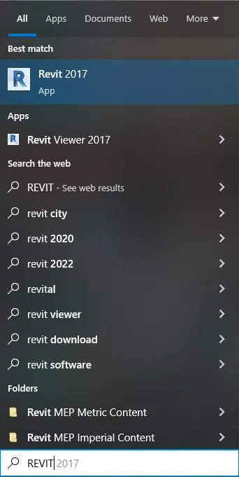
- Go to the Window search box to open a revit workspace.
- In window search bar type REVIT, the icon of revit application will show on the screen
STEP 2-
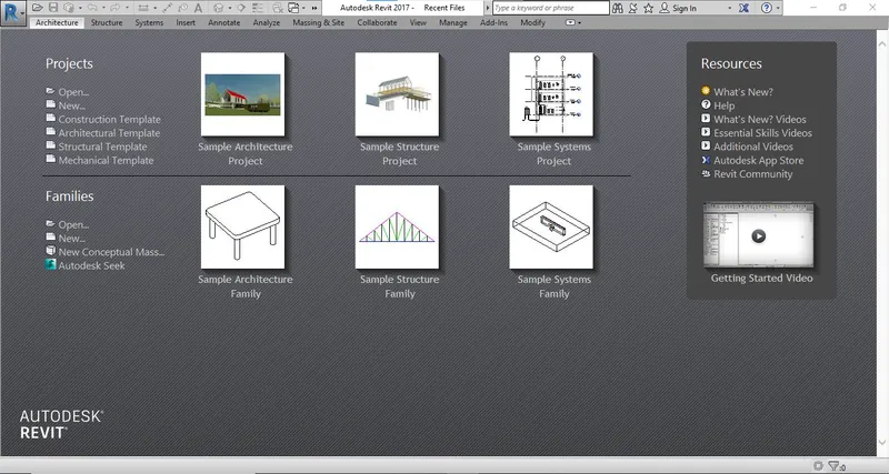
- Click on the icon of REVIT, application of revit will open and the user interface of revit will show on the screen.
STEP 3-
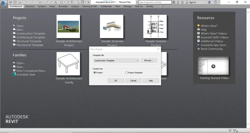
- Click on the new tab in the project drop down list a new dialog box will open
STEP 4-
- In the Dialog box of new project select the Template file and in create new select project and click on OK.
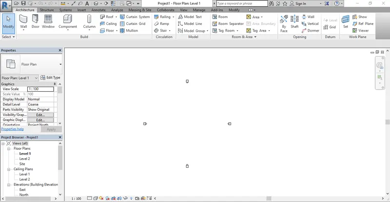
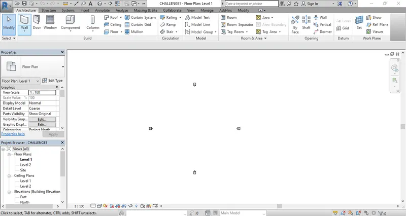
- A workspace of revit will open as shown in below picture.
STEP 5-
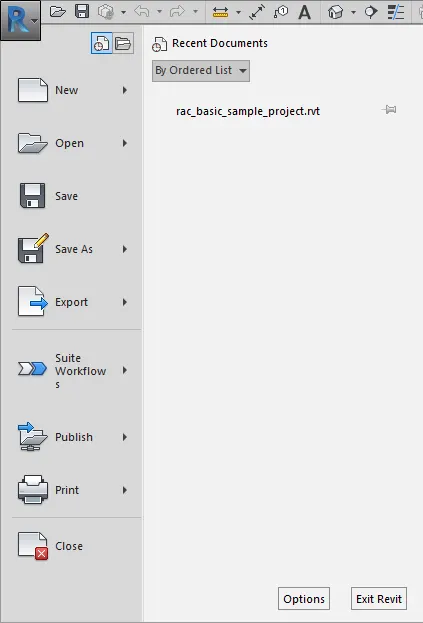
- Click on the application menu or R at the left-top corner of the screen.
- The application menu provides access to common file actions, such as New, Open, and Save. It also allows you to manage files using more advanced tools, such as Export and Publish and close tab to close the revit file.
STEP 6-
- Click on new and select the project tab, the shortcut key for New is Ctrl+N
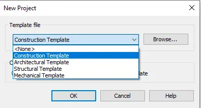
- A dialog box will open name as New project
- Select the Tempate file accouding to our project work as defaut these is four template Construction Template, Architectural Template, Structrual Template and Mechanical Template
- Here, I select a construction Template for my project.
STEP 7-
- Again, Click on the application menu or R at the left-top corner of the screen.
- The application menu provides access to common file actions, such as New, Open, and Save. It also allows you to manage files using more advanced tools, such as Export and Publish and close tab to close the revit file.
STEP 8-
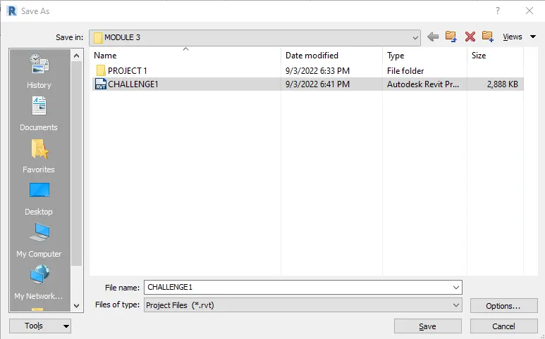
- Click on save as and select the project tab,
- A dialog box will open name as SAVE AS
- Select a File name and click on save.
-----------------------------------------------------------------------------------------------------
TASK 2- Save the new project file. Close and open using icons from the file toolbar
PROCEDURE -
STEP 1-
- Click on the application menu or R at the left-top corner of the screen.
- The application menu provides access to common file actions, such as New, Open, and Save. It also allows you to manage files using more advanced tools, such as Export and Publish and close tab to close the revit file.
STEP 2-
- Click on save as and select the project tab,
- A dialog box will open name as SAVE AS
- Select a File name and click on save.
STEP 3-
- Now these project is save name as challanges 1
STEP 4-
- Again, Click on the application menu or R at the left-top corner of the screen.
- The application menu provides access to common file actions, such as New, Open, and Save. It also allows you to manage files using more advanced tools, such as Export and Publish and close tab to close the revit file.
STEP 5-
- Now click on the close tab shown in file drop down to close the project.
STEP 6-
- Click on the Open in the project drop down list to open the exsisting project
- After click on the open the new dialog box will open with all save files.
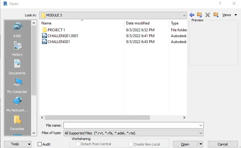
STEP 7-
- Click on the project file name as challange 1 and then click on open
- The existing project will open.
-----------------------------------------------------------------------------------------------------
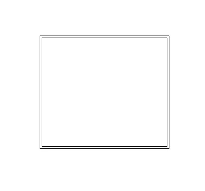
TASK 3- From the architecture/ structure toolbar familiarize yourself with options to draw a wall. Create a rectangular layout of walls of about 40’-0” X 35’-0”
PROCEDURE -
STEP 1-
- Open the window search box and type Revit and click on the application of revit the User interface of revit will open
- Click oon OPEN in the project drop down list and open the last project name as challange 1.
STEP 2-
- After open the project that is challanges 1 click on architecture tap to get access to Build tool
- For these project we required a wall which is present first in the architecture menu bar
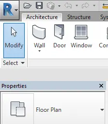
STEP 3-
- Click on the wall the drop down list of wall will open select the wall architecture that is non structural wall.
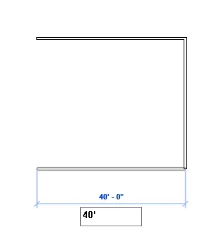
- Specify the first point of wall,give the direction by the mouse point and give the length of wall as 40'.
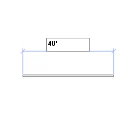
STEP 4-
- Again, Click on the wall the drop down list of wall will open select the wall architecture that is non structural wall.
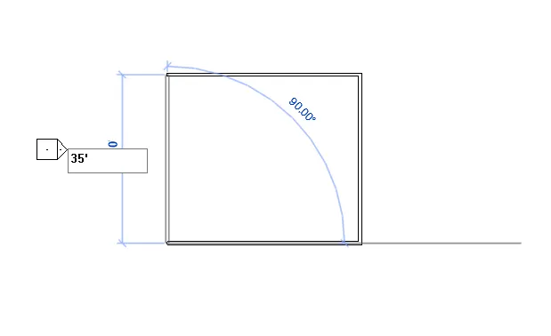
- Specify the first point of wall,give the direction by the mouse point and give the length of wall as 35'.
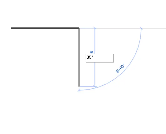
STEP 5-
- Click on the wall the drop down list of wall will open select the wall architecture that is non structural wall.
- Specify the first point of wall,give the direction by the mouse point and give the length of wall as 40'.
STEP 6-
- Again, Click on the wall the drop down list of wall will open select the wall architecture that is non structural wall.
- Specify the first point of wall,give the direction by the mouse point and give the length of wall as 35'.
RESULT-
-----------------------------------------------------------------------------------------------------
TASK 4- From the Annotate toolbar use the aligned option to add dimensions to the layout
PROCEDURE -
STEP 1-
- Open the last created wall layout in task 3
STEP 2-
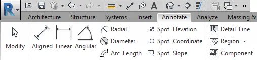
- Go to the ANNOTATE tab in the top menu bar a dimension tool wiill open.
STEP 3-
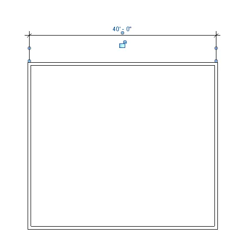
- Click on the Aligned dimension
- Specify the first point of dimension line as the starting point of wall and the next point is the end point of wall .
STEP 4-
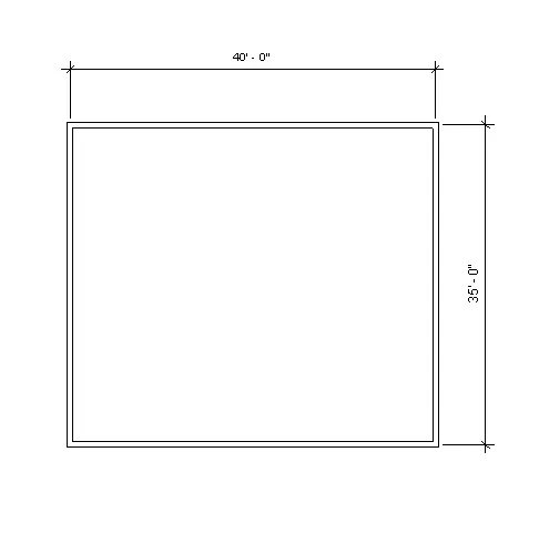
- Click on the Aligned dimension
- Specify the first point of dimension line as the starting point of vertical wall and the next point is the end point of vertcal wall .
-----------------------------------------------------------------------------------------------------
TASK 5- Use the properties browser to switch to different wall types
PROCEDURE -
STEP 1-
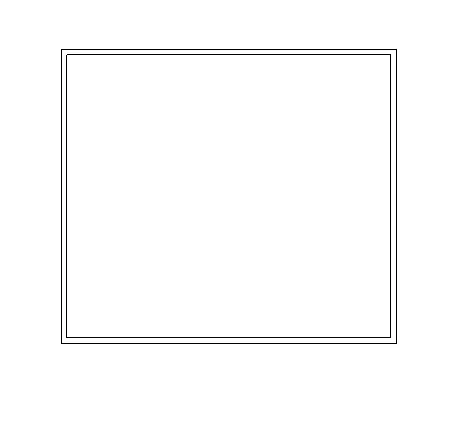
- Open the last created wall layout in task 3
STEP 2-
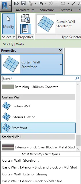
- Select the any wall among these four the properties and properties brower will open
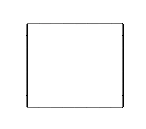
- Click on the wall type and select the wall aacording to our our here, I select a curtain wall storefront
STEP 3-
- Select the rest of the wall and repeat the same process
-----------------------------------------------------------------------------------------------------
TASK 6- Create a 3D view from the view toolbar and save the view with the appropriate name
PROCEDURE -
STEP 1-
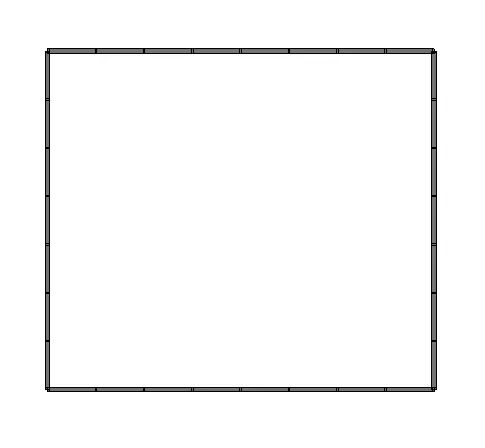
- Open the last created wall layout in task 5
STEP 2-
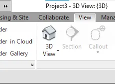
- Go to the view in the menu bar a create tool bar will open in which 3D view will present .
STEP 3-
- Click on 3D view a drop down will open selecct the defaut 3D view option
STEP 4-
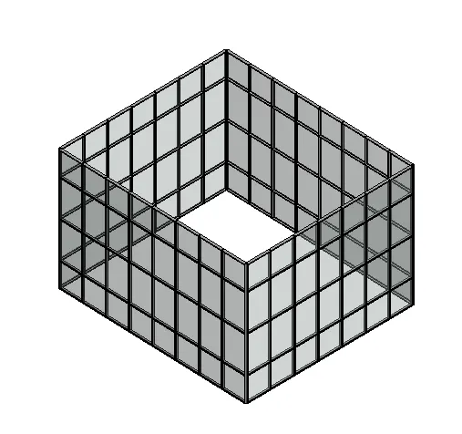
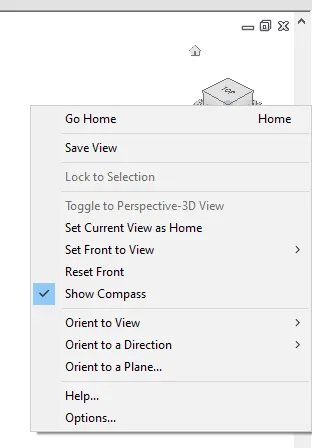
- Now select the view accourding to our used and right click on the view cube a new dialog box will open.
STEP 5-
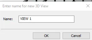
- Click on save view and give the name here i am give ass VIEW1
-----------------------------------------------------------------------------------------------------
TASK 7- Navigate through the 3D model using the view cube. Orbit/pan through the model layout created
PROCEDURE -
STEP 1-
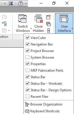
- Go to the view in the menu bar a create tool bar will open in which User Interface view will present .
- A drop down list will open ,click on viewcube and navigation bar to displace on screen.
STEP 2-
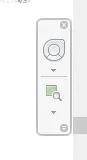
- Here we can see a bar that is nothing but the navigation bar which is now display on the screen
STEP 3-
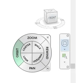
- Click on the navigation bar a new navigation wheel will be open as shown in picture.
STEP 4-
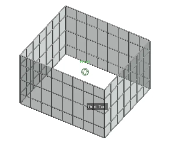
- Click on the ORBIT a orbit cursor will be display on the screen now we can orbit the object which is created in the task 5
STEP 5-
- Click on the navigation bar a new navigation wheel will be open as shown in picture.
STEP 6-
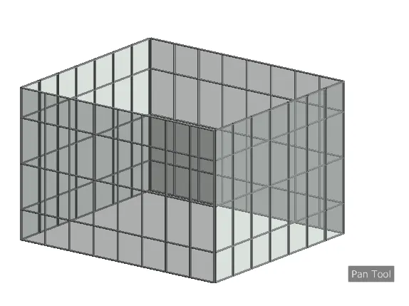
- Click on the PAN a pan cursor will be display on the screen now we can pan the object which is created in the task 5.
- Pan is nothing but the object will move with coordinate or we can say with the screen.
-----------------------------------------------------------------------------------------------------
TASK 8- Use the visibility settings option below to switch models to shaded, realistic, hidden lines options
PROCEDURE -
STEP 1-
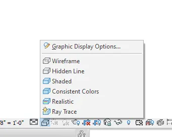
- At the bottom of the left cornor these is menu bar present, in the menu bar there is visual style tab click on that a drop down list will open
- in drop down list there is 6 type of visual style are present wireframe,Hidden line, shaded, Consistent Colors, Realistic and Ray Treace.
STEP 2-
- Click on SHADED we will get a shaded view of object
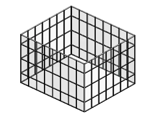
STEP 3-
- Click on HIDDEN we will get a hidden view of object
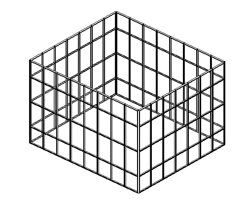
STEP 4-
- Click on REALISTIC we will get a realistic view of object
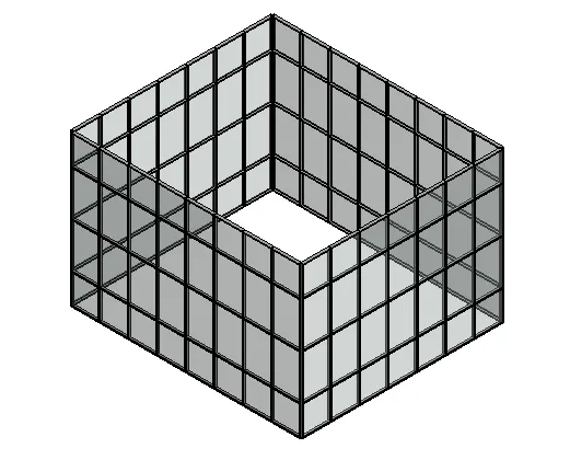
-----------------------------------------------------------------------------------------------------
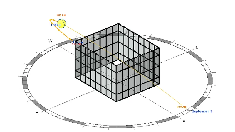
TASK 9- Turn the sun path on and off to view shadings in the layout created
PROCEDURE -
STEP 1-
- At the bottom of the left cornor these is menu bar present, in the menu bar there is a sun path tab click on that a drop down list will open
- in drop down list there is 3 type of sunpath are present sun path on, sun path off and sun setting .
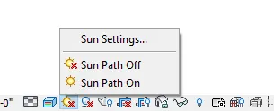
STEP 2-
- Click on sun setting a new dialog box is open of sun setting select the critaria accourding to project.
3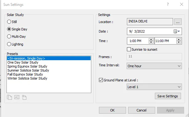
STEP 3-
- Then, again click on sun path tab and click on sun path on
RESULT -
-----------------------------------------------------------------------------------------------------
TASK 10- Use the Manage toolbar to enter project settings, project name, and project issue date (choose according to your convenience).
PROCEDURE -
STEP 1-
- Go to the manage tool bar here is a setting for project work
- Click on the project information

STEP 2-
- A new dialog box will open of project information
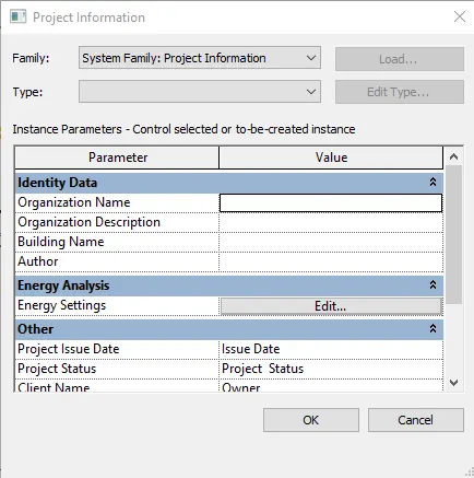
STEP 3-
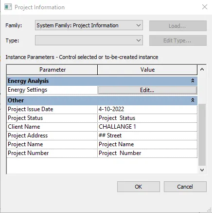
- In the project information dialog box scrool down we will get the other tab
- Change the Project Issue Date and Project name
-----------------------------------------------------------------------------------------------------
TASK 11- What is the Analyze toolbar used in Revit? How it is beneficial for design and modeling
PROCEDURE -
- The Analyze toolbar is available in Revit software, and it is a dedicated tab called "Analyze," which is shown in the below picture.
- We can perform structural analysis of the building using the Analyze tab, which has several options to enable the analysis process, the first of which is boundary condition, which defines the points, lines, and area boundary conditions in an analytical model.
- Then there's the load option, which adds point, line, and area loads to the model. Each load geometry is a family of instances and type parameters that add load by sketching or using host components.
- The next one is the load cases, which adds or edits load cases to the model. The load combination can add or edit the load combination for the analytical model setting. A load combination includes defining its name, formula, type, state, and usage.

-----------------------------------------------------------------------------------------------------
TASK 12- What are the links that Revit supports to be linked to the model?
PROCEDURE -
- Link Revit – Used to link another Revit model to the current model.
- Link IFC – Used to link IFC File as a reference, when we want to perform additional design work in Revit.
- Link CAD - Used to link the CAD file. To create 3D using Revit, we can link the cad file having 2D drawing.
- Link Topography – Used to link the existing topography to the current model

-----------------------------------------------------------------------------------------------------
TASK 13- Why do you need the Collaborate tab in Revit? How it supports modeling and its efficiency
PROCEDURE -
- The Collaboration tab in Revit enables work sharing through the working use of the same local area network in the same Revit model. That is how we used the collaborate tab in Revit.
- The Collaborate tab facilitates teamwork, cloud sharing, work sharing, and the Central Model. Multiple Revit models can be linked together, allowing users to work in contact when there is a need for collaboration to occur among users who are not in the same geographical location. By using Revit software, they can use multiple People can work together on a single project without any distribution
- Enabling work sharing involves creating a master project model known as the central model from an existing model. The central model stores the current owner information for all work and elements in the project and acts as the distribution point for all the changes made to the model. So all the users should have their own copy of the central model. They can edit locally in these workspaces, and they can also be synchronised with the central published model so other users can see their work. Revit is also extremely useful for MEP engineers who need to collaborate with another discipline while also supporting the model. So the collaboration tab keeps all the parties updated with the current project through work sharing by the cloud service It also allows the user to divide the model into a number of work sets, each of which can be model editable and non-editable by the current user to avoid confusion and lessen the load. Finally, it allows the user to define parameters as the design progresses and make model-wide changes in a quick and easy way.
