Introduction to REVIT concepts
1) From the file menu, create a new project (Structural / Architectural / Construction template ) and name the project appropriately.
AIM:
- To create the new project(struCtural/Architectural/Construction template) and name of the project appropriately.
INTRODUCTION OF REVIT:
- Revit architecture is designed to accommodate variousways to working, so that you can concentrate on your building models rather than on adapting to your methodology to software.
- Revit Architecture is a powerful building information modeling software for architects, engineers, designers and contractors. This fast-paced, intensive course guides students through introductory commands of Revit Architecture in order to produce working and presentation drawings.
PROCEDURE:
- First start the Rivet Software
- Then, From the model tab and click NEW.
- Then the new dialogue box will appear to te screen, click on metric-architectual template.
- then , press enter to OK.
- Finally new waorkspace will be loaded. And to name the project .
- Go to the file menu, save and enter the project as project 2.
RESULT:
- New file is created with name of project 2.
2) Save the new project file. Close and open using icons from file toolbar.
AIM:
- To save the project in REVIT software and close and open using in file toolbar
PROCEDURE:
STEP :1
- Go to the file menu, click the save option in it.
- Then , give name to the file and click save butoon.
- To change the location of the saved project, click on save as and enter a different location.
STEP :2
- To oppen a file, in the file menu open project.
STEP :3
- If want to close menu bar as same go to the menu click close option.
RESULT:
- The file is saved and opened and closely by file menu.
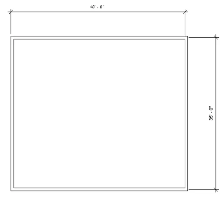
3) From the architecture/ structure toolbar familiarize with options to draw a wall. Create a rectangular layout of walls of about 40’-0” X 35’-0”
AIM:
- To Create a rectangular layout of walls of about 40’-0” X 35’-0”.
PROCEDURE:
- Open the rivet software, select new and select imperial- architectural template.
- clickon wall from the architectural tab - basic wall 8"
- Click on the floor plan area and enter 40'
- Move the mouse download and type 35'.
- Again type 40' placing the mouse to left.
- Again type 35' upwards
- A rectangle is created of 40'* 35'.
RESULT:
- WALL of 40'*35' is created using wall tool.
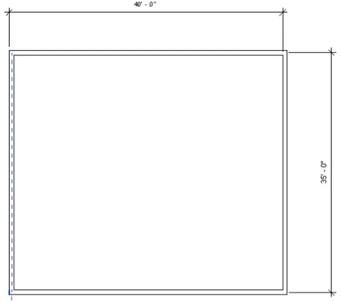
4) From the Annotate toolbar use the aligned option to add dimensions to the layout.
AIM:
- To the annotate toolbar use the aligned option to add dimensions to the layout.
PROCEDURE:
STEP1: Click on annotate toolbar.
STEP2: Click on aligned option.
STEP3: Click on the side of wall where the starts to the drag the dimendion line to the wherer we need.
STEP4: Similarly do the same on the others side.
RESULT:
- The dimension are done using annotate toolbar using aligned options.
5) Use the properties browser to switch to different wall types.
AIM:
- To Use the properties browser to switch to different wall types.
PROCEDURE:
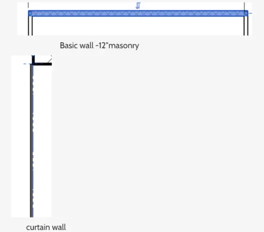
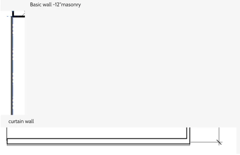
- Select the wall tool in the top of icon, then it has a many option sof wall types like curtain wall, masonry wall, basic wall.
- we use the wall one by one.
- Select the required the wall height and width.
RESULT:
- With the use of property browser, the wall type has been changed.
6) Create a 3D view from the view toolbar and save the view with the appropriate name.
AIM:
- To Create a 3D view from the view toolbar and save the view with the appropriate name.
PROCEDURE:
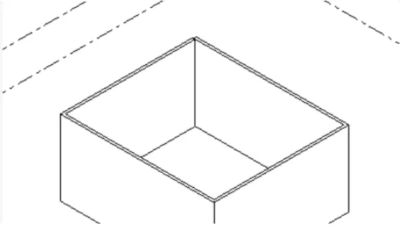
Step 1: press the view bar on the view cube on the right sided of the workspace.
Step 2: open the 3d view .
Step 3: click on the view template and click on create template from current view.
Step 4: Then the view dialogue box, insert the name as 3d view and click ok.
Step 5: The view will be created and we can take the view from apply template properly to current view.
RESULT:
- The 3d view is created by and saved it by name 3d view.
7) Navigate through the 3D model using the view cube. Orbit/pan through the model layout created
AIM:
- To Navigate through the 3D model using the view cube. Orbit/pan through the model layout created
PROCEDURE:
Step1: press the view bar on the view cube on the right sided of the workspace.
Step2: And click the different views.
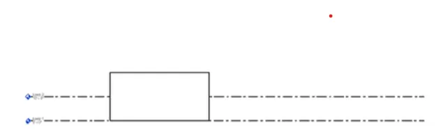
Step3: To pan, cllick on the navigation wheel below the view cube.
Step4: Click on the option. To view the navigation view of the view bars.
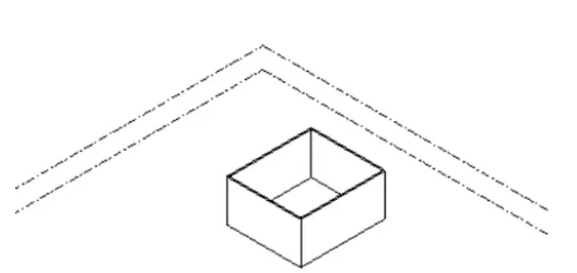
Step5: Click on the left the cursor and move the mouse to pan.
RESULT:
- Use of view cube and pan/orbit in navigation wheel is shown.
8) Use the visibility settings option below to switch model to shaded, realistic, hidden lines options.
AIM:
- To Use the visibility settings option below to switch model to shaded, realistic, hidden lines options.
PROCEDURE:
Step1: Click on the cube at the bottom toolbar-visual style.
Step2: Select the hidden line.
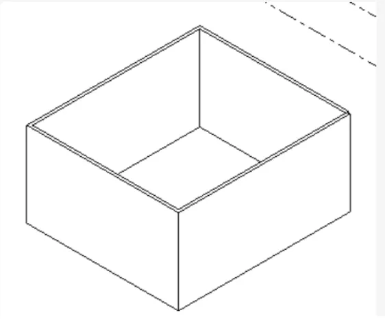
Step3: select the model shaded.
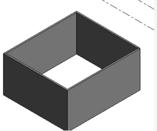
Then like wise realistic view.
RESULT:
- Hidden lines, shaded, realistic options are done by visibillity settings.
9) Turn the sun path on and off to view shadings in the layout created.
AIM:
- To on and off sunpath to view the shadings in layout.
PROCEDURE:
Step1: Click on the icon of sun on bottom toolbar.
Step2: Click it so that the sun path is on.
Step3: Date and time will be visible.
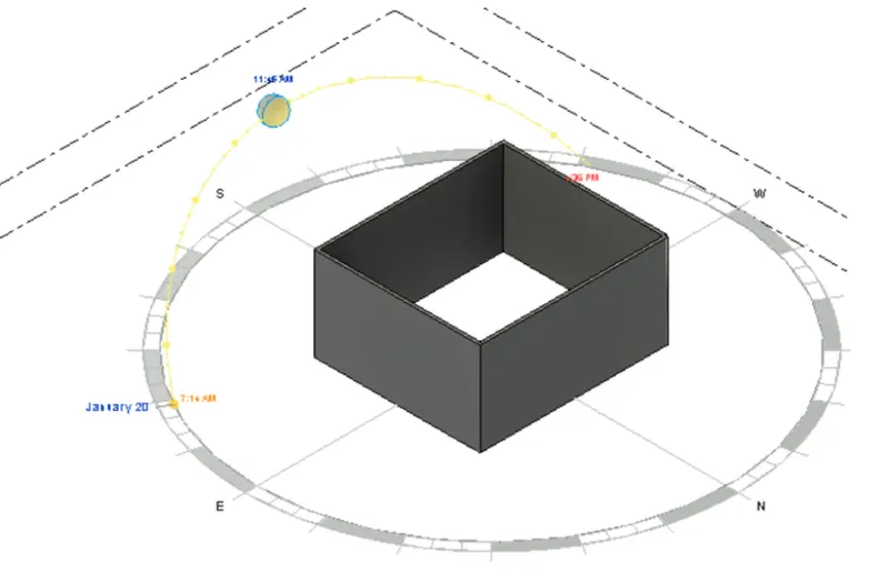
- Similarly put the sun path off.
RESULT:
- Use of sunpath on/off is done.
10) Use the Manage toolbar to enter project settings, project name, and project issue date (choose according to your convenience).
AIM:
- To using manage the toolbar to enter project setting, name and issue date.
PROCEDURE:
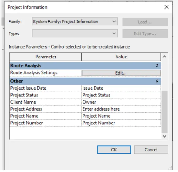
Step1: click the managetoolbar, and project information.
Step2: Project information dialogue box appears.
Step3: From the other click on project issue date and give a value.
Step4: Similarly select the project name, project status, client name, project address and project address and project number.
RESULT:
11) What is the Analyze toolbar used in Revit? How it is beneficial for design and modeling.
Aim:
- To Analyze toolbar in Revit and its benefits.
PROCEDURE:
- Analyze toolbar in Rivet helps in evaluating the building performance - analyzing the model by boundary conditions, loads etc.,
- It evaluates the sustainability of the model.
BENEFITS OF ANALYZE THE TOOL FOR DESIGN AND MODELLING:
STRUCTURAL ANALYSIS it hasbeen:
- Boundary condition: We can give the line and area boundary conditions to the model.
- Loads : We can apply point, line and area load to the model.
- Load cases: We can add and edit the load cases.
- Load combinations: To add load combinations.
- It also help to perform energy optimization and energy analysis.
- For energy analysis it has features.
HEATING AND COOLING LOADS ANALYSIS:
- To create heating and cooling load analysis report, useful for mechanical enigeers for ventilations ducts or heating and cooling systems.
- Rivet allows to perform analysis in multiple disciplines, so when collabrating in every discipline they can perform their own task seperately and come together as a team to show progress.
- we can achieve the progress of project together from all discipline.
12) What are the links that Revit supports to be linked to the model?
AIM:
- To links in Revit.
PROCEDURE:
In insert tab links are found.
- It is used to link different files to the file current file.
LINK REVIT:
- It allows to link another rivet model to the current model.
LINK IFC:
- To link ifc file to current model to reference its information for additional design works.
LINK Cad:
- To link the 2d cad file to current rivet file to create 3d by rivet tools.
LINK TOPOGRAPHY:
- To link to the current model
MANAGE LINKS:
- Provides features to manage the links to the building models.
13) Why do you need the Collaborate tab in Revit? How it supports modeling and its efficiency?
- Revit provides several different ways to collaborate with team members who are also using the software.
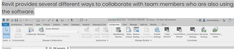
- Helps link multiple Revit models together, simultaneously allowing other team members to work in the background.
- Users on the same local area network (LAN) can work together in the same Revit model using Revit Work Sharing.
- When collaboration needs to occur among users who are not in the same geographic location, use Revit Server or Revit Cloud Work-sharing.
- Revit Server connects offices that share a network but are not in the same geographic location.
- Revit Cloud Work-sharing is a cloud-based service that allows any Revit users inside or outside a network to collaborate on Revit model.
- Revit Cloud Work-sharing helps in modeling with efficiency
- As the Revit Cloud Work-sharing service helps to author Revit models in the cloud concurrently with other team members.
- Before Revit users collaborate on a model in the cloud, you must upload the model from Revit to BIM 360 Document Management. During the upload process, the following events occur:
- If the model does not yet have work-sharing enabled, work-sharing is automatically enabled, the Revit model is uploaded to the BIM 360 project, and a locally-cached version is created on your computer.
- If the model is already work shared, the Revit model is uploaded to the BIM 360 project, and a locally-cached version is created on your computer.
- As alternatives to using Revit Cloud Work-sharing, you can use Revit Server to collaborate across a wide area network (WAN) or file-based work-sharing to collaborate across a local area network (LAN).