Introduction to REVIT concepts
1) From the file menu, create a new project (Structural / Architectural / Construction template ) and name the project appropriately
AIM:
To create the new project(structural/Architectural/Constructio n template)and name of the project appropriately.
INTRODUCTION OF REVIT.:
Revit architecture is designed to accommodate variousways to working, so that you can concentrate on your building models rather than on adapting to your methodology to software.
Revit Architecture is a powerful building information modeling software for architects, engineers, designers and contractors. This fast-paced, intensive course guides students through introductory commands of Revit Architecture in order to produce working and presentation drawings.
PROCEDURE:
1) First start the Rivet Software
2) Then, From the model tab and click NEW.
3) Then the new dialogue box will appear to te screen, click on metric architectual template.
4) then, press enter to OK.
5) Finally new waorkspace will be loaded. And to name the project.
6) Go to the file menu, save and enter the project as project 2.
RESULT:
New file is created with name of project 2.
2. Save the new project file. Close and open using icons from file toolbar.
AIM:
To save the project in REVIT software and close and open using in file toolbar
PROCEDURE:
STEP 1). Go to the file menu, click the save option in it. Then, give name to the file and click save butoon.
To change the location of the saved project, click on save as and enter a different location.
STEP 2). To oppen a file, in the file menu open project.
STEP3). If want to close menu bar as same go to the menu click close option.
RESULT:
The file is saved and opened and closely by file menu.
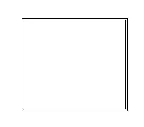
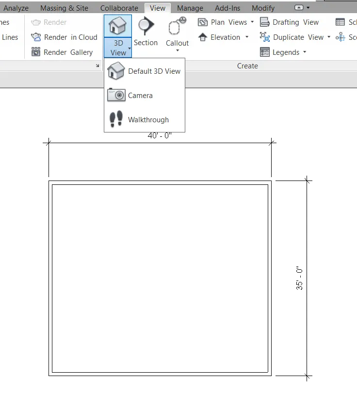
3). From the architecture/ structure toolbar familiarize with options to draw a wall. Create a rectangular layout of walls of about 40'-0" x 35'-0"
AIM:
To Create a rectangular layout of walls of about 40'-0" X 35'-0".
PROCEDURE:
1). Open the rivet software, select new and select imperial- architectural template.
2). clickon wall from the architectural tab basic wall 8"
3). Click on the floor plan area and enter 40
4). Move the mouse download and type 35'.
5). Again type 40' placing the mouse to left.
6). Again type 35' upwards
7). A rectangle is created of 40" 35".
RESULT:
WALL of 40*35' is created using wall tool.
4). From the Annotate toolbar use the aligned option to add dimensions to the layout.
AIM:
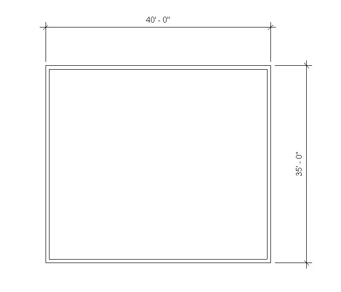
To the annotate toolbar use the aligned option to add dimensions to the layout.
PROCEDURE:
STEPI: Click on annotate toolbar.
STEP2: Click on aligned option.
STEP3: Click on the side of wall where the starts to the drag the dimendion line to the wherer we need.
STEP4: Similarly do the same on the others side.
RESULT:
The dimension are done using annotate toolbar using aligned options.
5). Use the properties browser to switch to different wall types.
AIM:
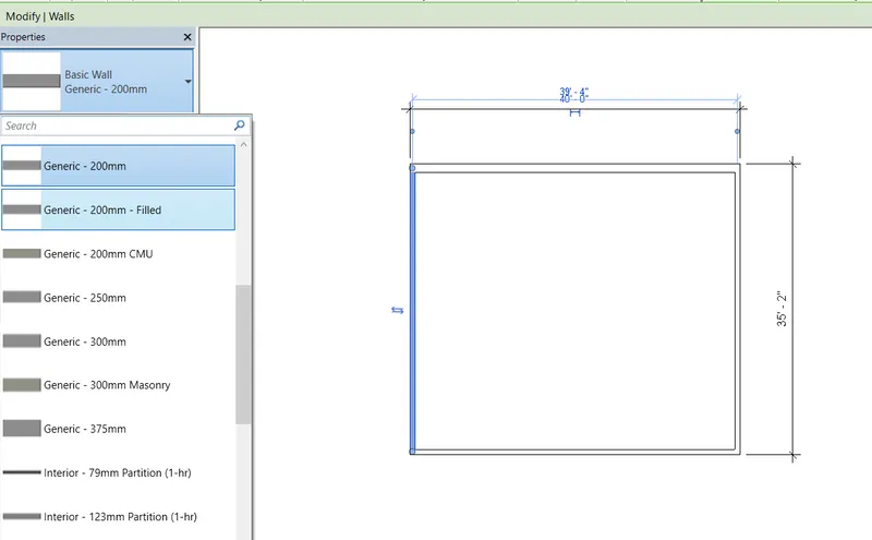
To Use the properties browser to switch to different wall types.
PROCEDURE:
1). Select the wall tool in the top of icon, then it has a many option sof wall types like curtain wall, masonry wall, basic wall.
2). we use the wall one by one.
3). Select the required the wall height and width.
RESULT:
With the use of property browser, the wall type has been changed.
6). Create a 3D view from the view toolbar and save the view with the appropriate name.
AIM:
To Create a 3D view from the view toolbar and save the view with the appropriate name.
PROCEDURE:
Stepl: press the view bar on the view cube on the right sided of the workspace.
Step 2: open the 3d view.
Step 3: click on the view template and click on create template from current view.
Step 4: Then the view dialogue box, insert the name as 3d view and click ok.
Step 5: The view will be created and we can take the view from apply template properly to current view.
RESULT:
The 3d view is created by and saved it by name 3d view.
7). AIM:
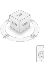
To Navigate through the 3D model using the view cube. Orbit/pan through the model layout created
PROCEDURE:
Stepl: press the view bar on the view cube on the right sided of the workspace. Step 2: And click the different views.
Step3: To pan, cllick on the navigation wheel below the view cube.
Step 4: Click on the option. To view the navigation view of the view bars.
Step 5: Click on the left the cursor and move the mouse to pan.
RESULT:
Use of view cube and pan/orbit in navigation wheel is shown.
8) Use the visibility settings option below to switch model to shaded, realistic, hidden lines options.
AIM:
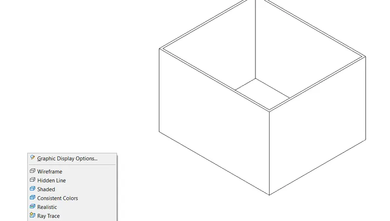
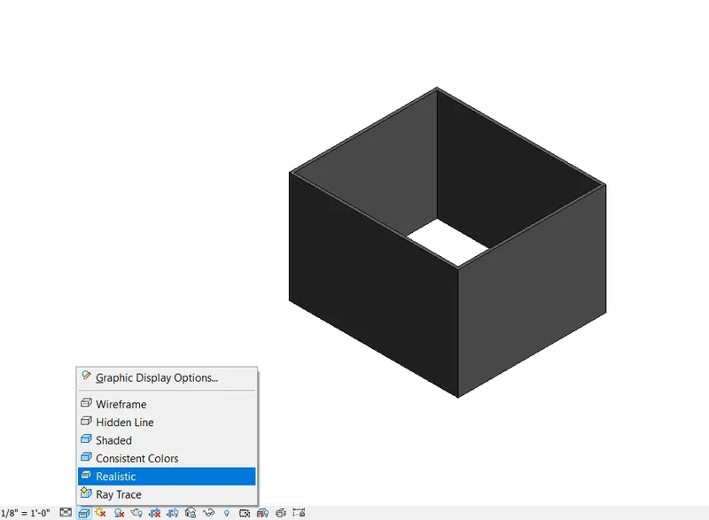
To Use the visibility settings option below to switch model to shaded, realistic, hidden lines options.
PROCEDURE:
Stepl: Click on the cube at the bottom toolbar-visual style.
Step2: Select the hidden line.
Step3: select the model shaded.
Then like wise realistic view.
RESULT:
Hidden lines, shaded, realistic options are done by visibility settings.
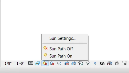
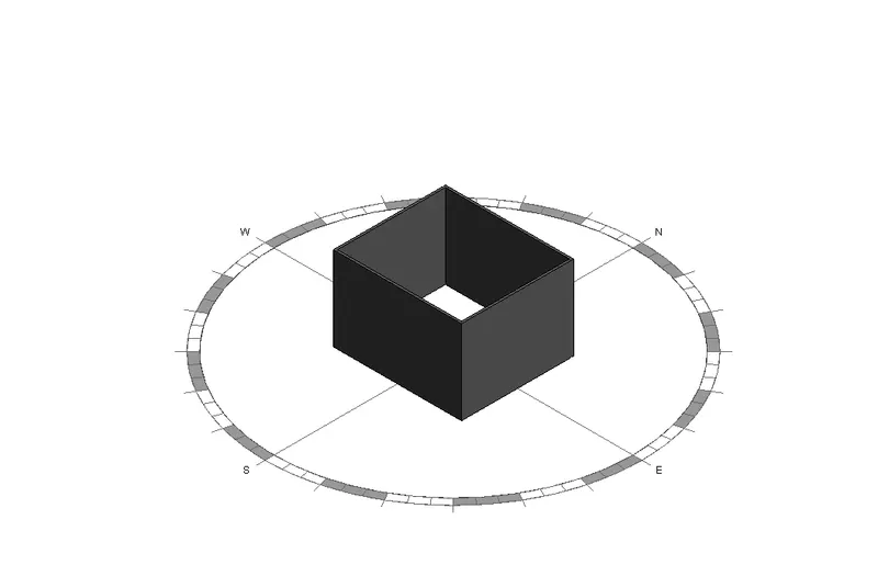
9). Turn the sun path on and off to view shadings in the layout created.
AIM:
To on and off sunpath to view the shadings in layout.
PROCEDURE:
Stepl: Click on the icon of sun on bottom toolbar.
Step2: Click it so that the sun path is on.
Step3: Date and time will be visible.Similarly put the sun path off.
RESULT:
Use of sunpath on/off is done.
10). Use the Manage toolbar to enter project settings, project name, and project issue date (choose according to your convenience).
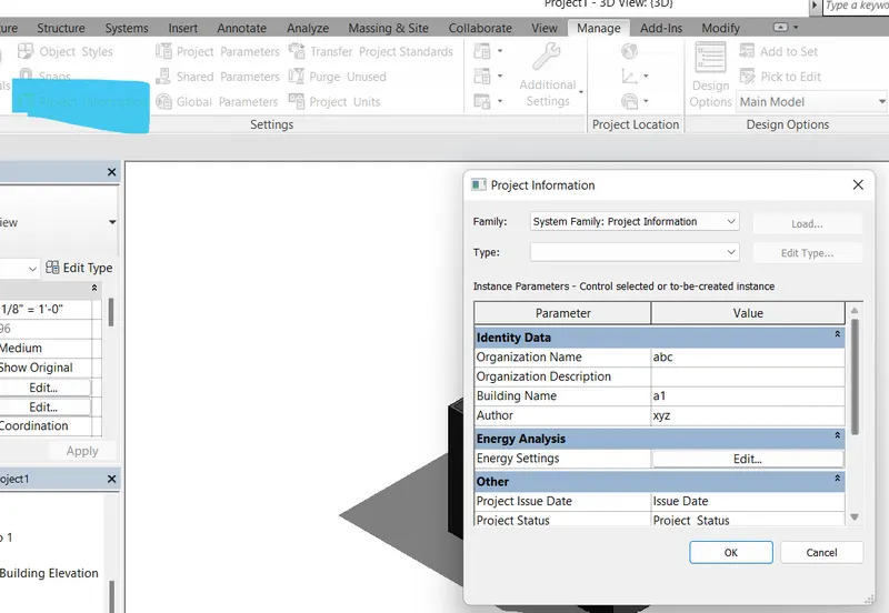
AIM:
To using manage the toolbar to enter project setting, name and issue date.
PROCEDURE:
Step 1: click the managetoolbar, and project information.
Step2: Project information dialogue box appears.
Step3: From the other click on project issue date and give a value.
Step4: Similarly select the project name, project status, client name, project address and project address and project number.
RESULT:
11). What is the Analyze toolbar used in Revit? How it is beneficial for design and modeling.
Aim:
To Analyze toolbar in Revit and its benefits.
PROCEDURE:
1. Analyze toolbar in Rivet helps in evaluating the building performance - analyzing the model
by boundary conditions, loads etc.,
2. It evaluates the sustainability of the model.
BENEFITS OF ANALYZE THE TOOL FOR DESIGN AND MODELLING:
STRUCTURAL ANALYSIS it hasbeen:
Boundary condition: We can give the line and area boundary conditions to the model.
Loads: We can apply point, line and area load to the model.
Load cases: We can add and edit the load cases.
Load combinations: To add load combinations.
It also help to perform energy optimization and energy analysis. For energy analysis it has features.
HEATING AND COOLING LOADS ANALYSIS:
-To create heating and cooling load analysis report, useful for mechanical enigeers for ventilations ducts or heating and cooling systems.
- Rivet allows to perform analysis in multiple disciplines, so when collabrating in every discipline they can perform their own task seperately and come together as a team to show progress.
- we can achieve the progress of project together from all discipline.
12). What are the links that Revit supports to be linked to the model?
AIM:
TO LINKS in Revit.
PROCEDURE:
In insert tab links are found. It is used to link different files to the file current file.
LINK REVIT: It allows to link another rivet model to the current model.
LINK IFC: To link ifc file to current model to reference its information for additional design works.
LINK Cad: To link the 2d cad file to current rivet file to create 3d by rivet tools.
LINK TOPOGRAPHY: To link to the current model.
MANAGE LINKS: Provides features to manage the links to the building models.
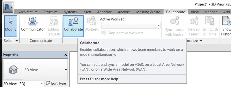
13) Why do you need the Collaborate tab in Revit? How it supports modeling and its efficiency?
It is the features which help to collabrate and help the team members to work on the model simultaneously.
In modelling it helps the team members of different disciplines to work on the same file simultaneously
The efficiency of the moddeling will behigh, as the work can be finished faster
We do not have to wait for one model to be completed to start the model ofnext discipline.