Introduction to REVIT concepts
1
aim:
From the file menu, create a new project (Structural / Architectural / Construction template) and name the project appropriately
Open the revit 2020 software and then go to the file menu and > select new > then select the project > next in the options of the Structural / Architectural / Construction template select the Architectural template > then click OK
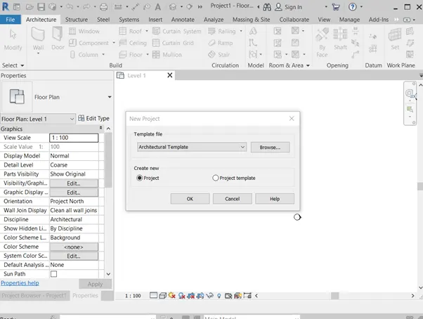
Next for saving the project
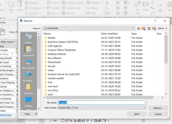
In the revit file go to file menu and > select the save as and the n > select the project > name the project file with the required name
By this the naming of the project is done.
Result:
new project is created
2)
Aim:
Save the new project file. Close and open using icons from file toolbar
saving the project
In the revit file go to file menu and > select the save as and the n > select the project > name the project file with the required name
Then for opening the file
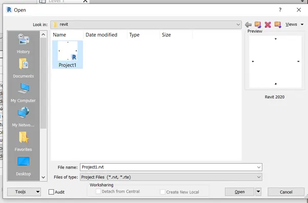
Go to file > select the open option > select the project > in the project browser go to the saved location select the required project and click on the open
Result:
project file is saved.
3)
Aim:
From the architecture/ structure toolbar familiarize with options to draw a wall. Create a rectangular layout of walls of about 40’-0” X 35’-0”
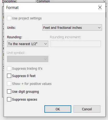
In command prompt type un and wake the units
And then change the units as the feet and fractional inches
Select the architecture tab in the > select the wall option
Now in the spaceclick on the space and align the wall horizontally and type 40’ (xdirection) and then from there vertically draw the wall at the 35’ (ydirection) then with the help of the snapping option snap it along the line and then close the wall boundary by connecting it to the start point.
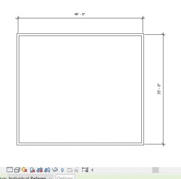
Result:
wall is drawn in the Revit.
4)
Aim:
From the Annotate toolbar use the aligned option to add dimensions to the layout
For the dimensions of the layout go to the annotate option in the menu bar and the select the aligned option the annotation
Then move the cursor towards the wall and then click on the wall when middle line is displayed in the wall and similarly snap it to the opposite wall or the required wall distance that has to be measured and release. Similarly carry out the process in the other direction also
Therefor the aligned dimension is obtained for the layout
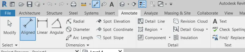
Result:
the aligned dimension is obtained for the layout
5)
Aim:
Use the properties browser to switch to different wall types
For switching the wall types using the properties browser:
First click on the wall that’s type has to be changed and then properties bar will be popped where walls properties will be displayed
There click on the type of the wall where there will be the drop down of the different types of the wall and then click on the desired wall type and the wall type will be changed to the respective wall type.
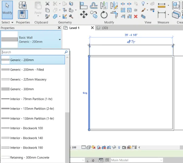
result:
switching the wall types
6)
Aim:
Create a 3D view from the view toolbar and save the view with the appropriate name
For creating the 3d view of the structure click on the view bar and then click on the 3d view icon
Then for changing the name of the view as it will be 3d view default:
Go to the project browser > then click on the 3D views >then check for the required view and right click on the view name and select the rename option and change the name of the view
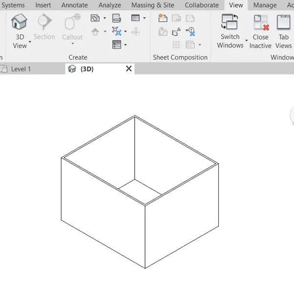
Result:
3D view of the model
7)
Aim:
Navigate through the 3D model using the view cube. Orbit/pan through the model layout created
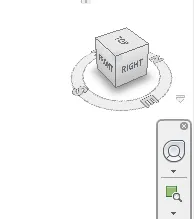
Usually, the view cube is located in the top right corner we can use this view cube for the views of the model at the different angles of the model
We can see the front elevation, back elevation and 2 side elevations in 1 click even we can obtain the top and bottom view of the model.
Next by long press of the left click on the view cube we can pan or rotate the model for obtaining the required view of the model
And right clicking on the view cube we have other options of the orientation and save view etc can be done.
These are the uses of the view cube
Result:
learned how to navigate through the view cube.
8)
Aim:
Use the visibility settings option below to switch model to shaded, realistic, hidden lines options
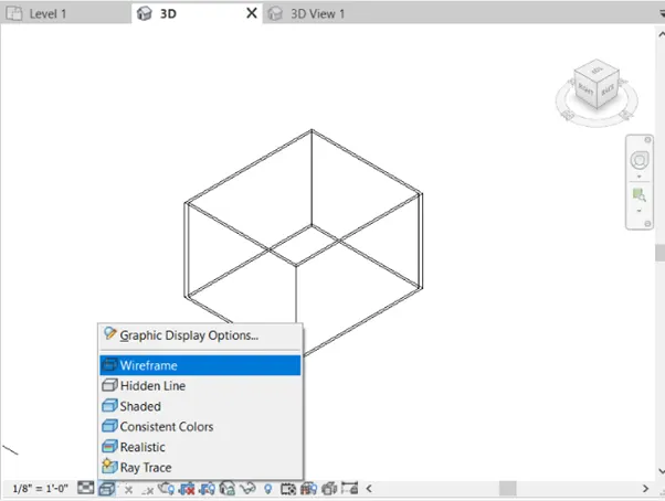
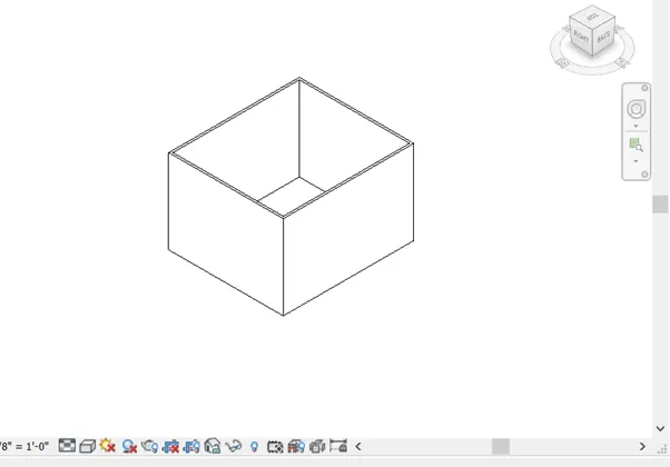
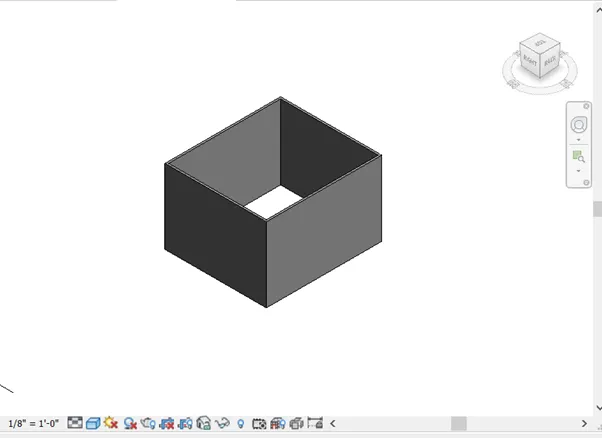
With the help of the visibility settings we can switch model to shaded, realistic, hidden lines options as shown in the figures below:
Wire frame
Hidden line
Shaded
Consistent colour
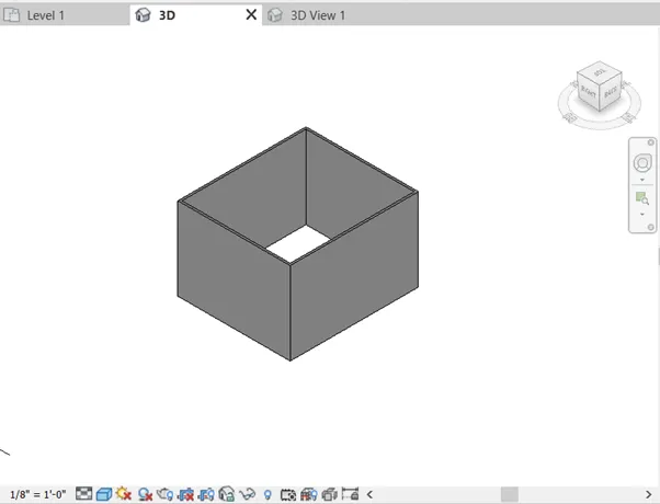
Realistic
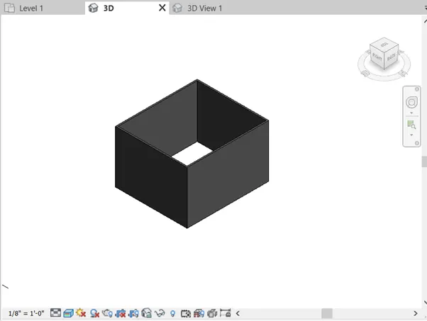
Ray trace
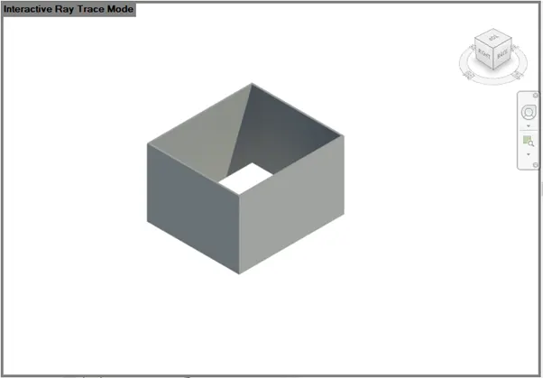
Result:
different visibilties were shown.
9)
Aim:
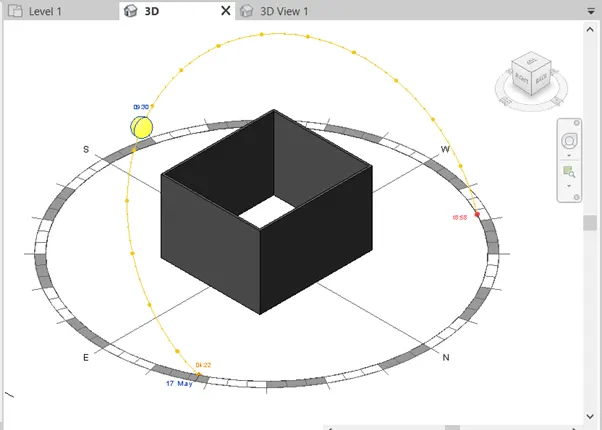
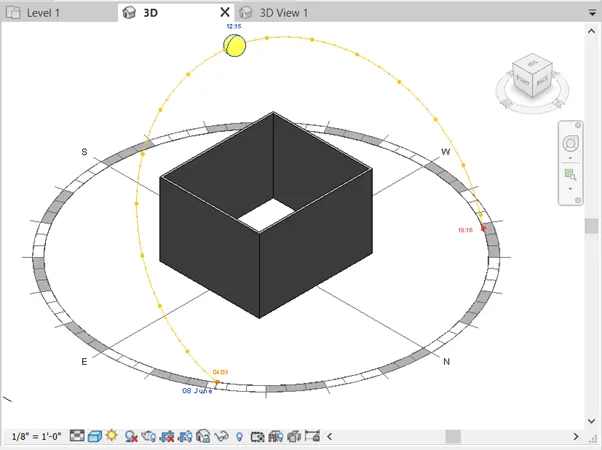
Turn the sun path on and off to view shadings in the layout created
Sun path is located beside the visibility settings and we can turn off and on it by the single click
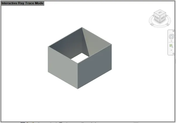
And below images are the some of the examples of the shading for the respective sun path.
Result:
gained knowledge over the sun path
10)
Aim:
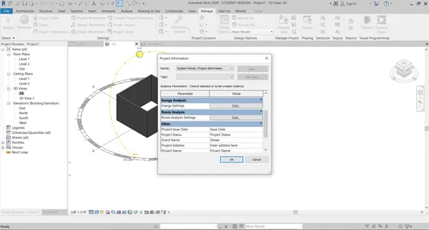
Use the Manage toolbar to enter project settings, project name, and project issue date (choose according to your convenience).
In the menu bar first go to the manage toolbar and then go and click on the project information icon visible in the manage toolbar and then there will be a pop up of the project information box where the required information like project settings, project name, and project issue date etc, can be entered as according to our convenience as shown in the figure below
Result:
project details were entered
11)
Aim:
What is the Analyze toolbar used in Revit? How it is beneficial for design and modelling
Analyse tool bar present in the menu bar of the Revit is used to perform structural buildings analysis it helps in defining the point line and the area boundary conditions and some of the load also can be applied on the model and the analysis can be done for the structure according to the desired design standards
We can also find out the energy optimization of the structure we are modelling and also check the sustainability of the structure.
12)
Aim:
What are the links that Revit supports to be linked to the model?
The different links that Revit supports are:
Link Revit, link ifc, link cad
With these links we can link any Revit model that is useful for the current Revit model where we are working by the link Revit command
And with help of the link IFC and link CAD we can add the IFC and 2D cad filed respectively
13)
Aim:
Why do you need the Collaborate tab in Revit? How it supports modelling and its efficiency
Collaborate tool helps to collaborate all the required models in the one Revit file which helps in the better understanding of all the team members on the work as all their work will be collaborated to that model
This collaboration can be done via both the LAN connection and also by the use of the network.