Introduction to REVIT concepts
1. AIM - From the file menu, create a new project (Structural / Architectural / Construction template ) and name the project appropriately.
Procedure -
Step 1)
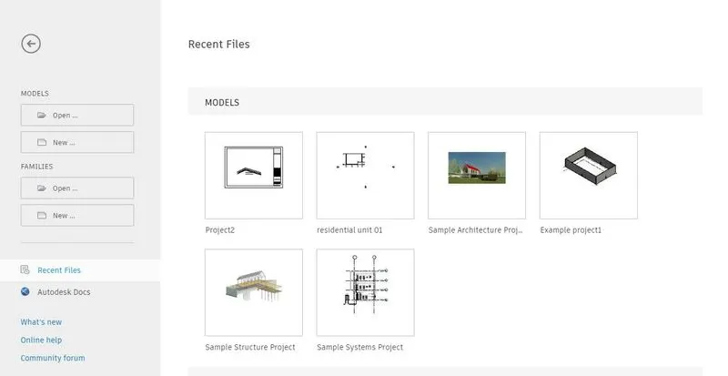
Open Revit 2022 from windows.
Step 2)
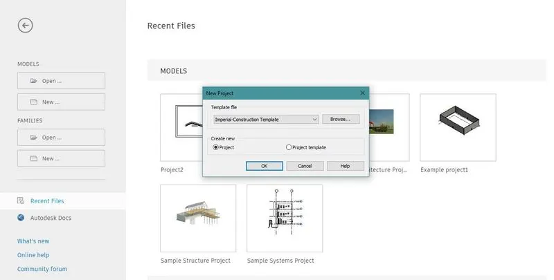
Click on New Project Tab which opens the new project dialogue box choose Imperial Construction template from the template file drop down menu and select project from the Create new option.
2. AIM - Save the new project file. Close and open using icons from file toolbar
Procedure -
Step 1)
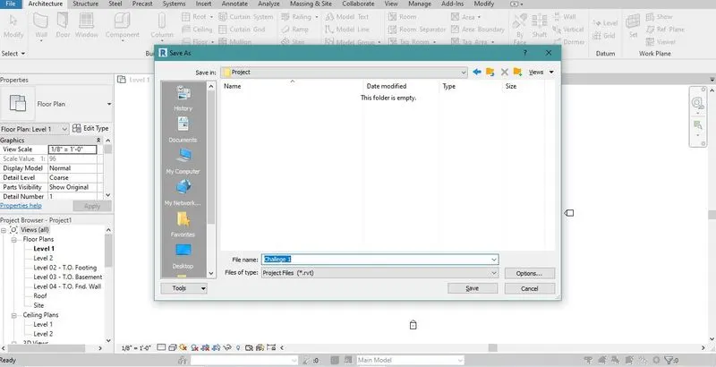
After the file is opened click on Save As option on the file menu tab and select an appropriate name for the project file with the required location and click on save.
Step 2) Close the file
Step 3)
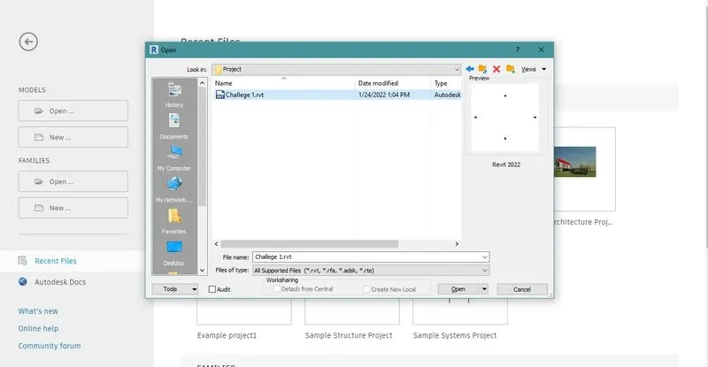
Open Revit 2022 click on Open tab on file menu select the file from the location saved and click on open.
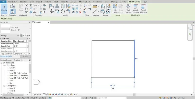
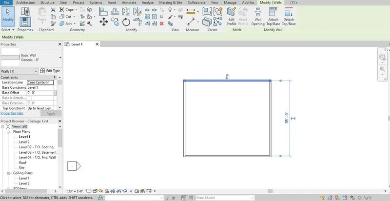
3. AIM - From the architecture/ structure toolbar familiarize with options to draw a wall. Create a rectangular layout of walls of about 40’-0” X 35’-0”
Procedure -
Step 1) After opening the file click on the Architectural tab on the file menu and click on Wall tab which opens different options such as Wall Architectural, Wall Structural. Select Wall - Architectural.
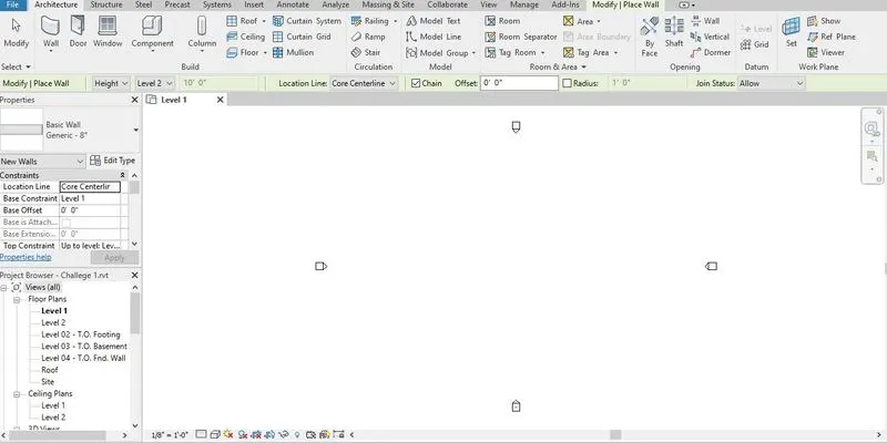
Step 2) in the properties section Wall - Architectural default prperty is selected as Basic Wall - Generic - 8".
Click on any point from where the wall will start and drag till it measures 40' - 0" in the longitudnal direction and then right to end the length and left click again to start the wall for the lateral direction for 35'-0" and repeat again for complete surrounding walls.
4. AIM - From the Annotate toolbar use the aligned option to add dimensions to the layout
Procedure -
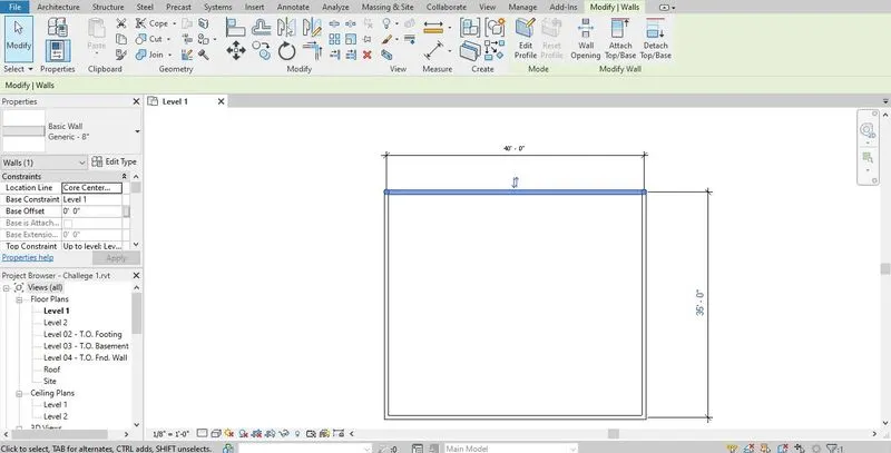
Step 1) After click on Annotate tab on the file toolbar select the centerpoint of the walls in each direction and drag the dimensions above the walls.
5. AIM - Use the properties browser to switch to different wall types
Procedure-
Step 1) On the left corner of the Revit window click on the Basic wall generic - 8" after the wall the changes are required is selected and a drop down optionsopens up. Select wall dimensions 12".
6. Create a 3D view from the view toolbar and save the view with the appropriate name.
Procedure -
Step 1) After clicking on view tab select 3D View and in the drop down options select default 3D view.
Step 2) CLick on Modify tab and then select Type properties
Step 3) On the right side of the popup box click on Duplicate for the Family: System Family : 3D View and Type: 3D View and select an appropriate name.
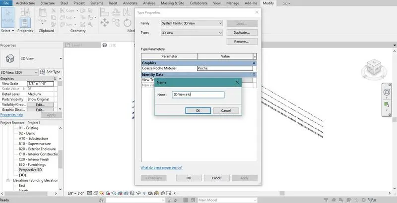
I have chosen 3D view a-b.
7. AIM - Navigate through the 3D model using the view cube. Orbit/pan through the model layout created
Procedure -
Step 1) Above the navigation toolbar the view cube is visible, by clicking on top the view goes to the top as well as by rotating the cube the view field changes.
Step 2) By clicking on SHIFT+W a new toolbar appears which consists of PAN/ZOOM/REWIND option after clicking on Pan option left click on the portion of the layout and drag through the part.
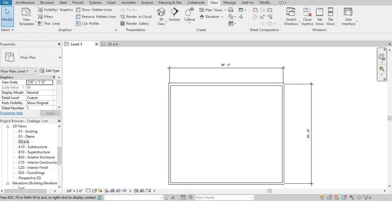
8. AIM - Use the visibility settings option below to switch model to shaded, realistic, hidden lines options
Procedure -
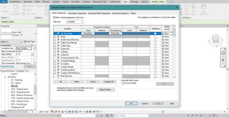
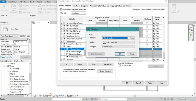
Step 1) Open View Menu and select Visibility/Graphics tab which opens visibilty/graphics overide control panel.
Step 2) In the Model Categories tabdrop down to select wall categories and crick on Overide option to change the Projection/surface. After clicking on the pattern graphic a new dialogue box opens up where Foreground and background patters and repective colors can be selected.
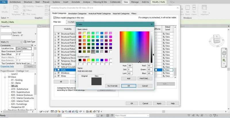
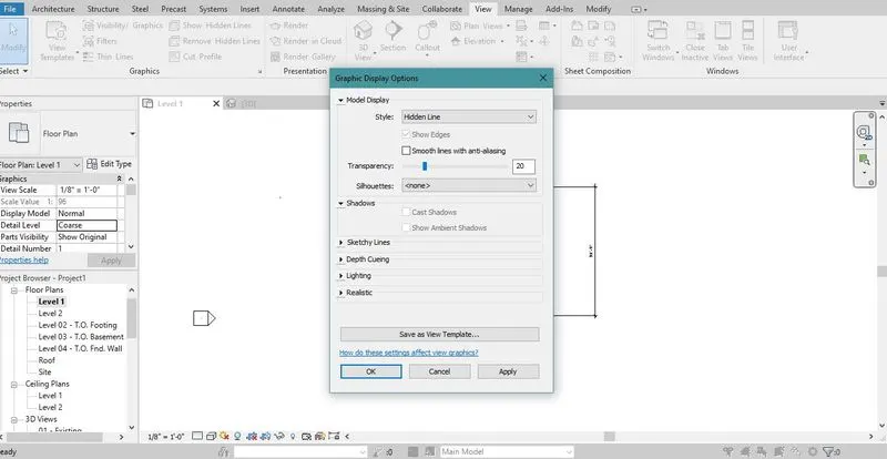
Alternatively, In the ribbon on the bottom of the screen next to detail level tab left click which opens the Graphic display options with other options such as wireframe/hidden line/shaded/consistent colors/realistic. After selecting Graphic display option in the Model Display Menu Select Hidden Line/Shaded/consistant colors/Realistic as Style and click on 10 for transparency and click apply and close.
9. AIM - Turn the sun path on and off to view shadings in the layout created
Procedure -
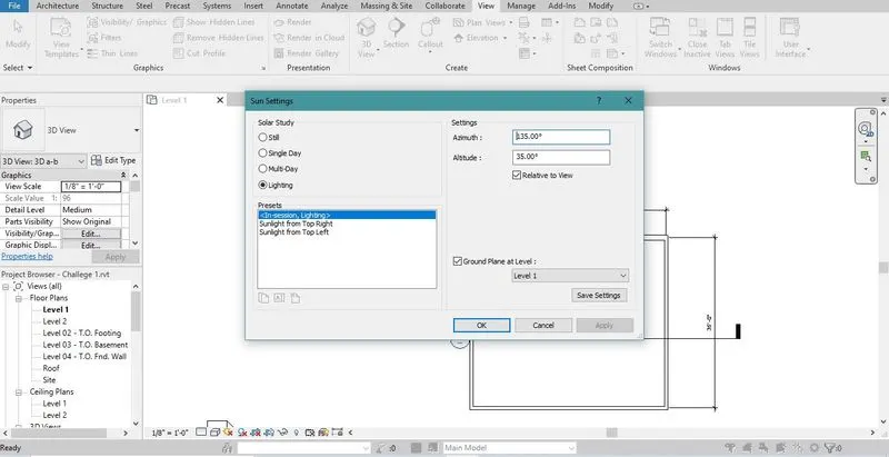
Step 1) Select by Left clicking on the Sun Path tab on the ribbon on the bottom of the screen on the Properties palette next to the Graphic Display option and select either Enable Sun Path or Disable Sun Path.
10. AIM - Use the Manage toolbar to enter project settings, project name, and project issue date (choose according to your convenience).
Procedure -
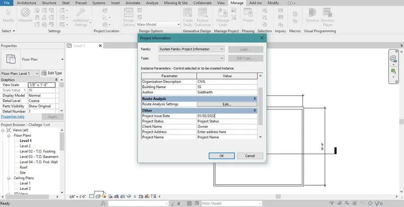
Step 1) Click on Manage Tab and select Project Information option and type in the required details like Project name, Project issue date and click on OK.
11. AIM - What is the Analyze toolbar used in Revit? How it is beneficial for design and modeling
Answer - Analyze toolbar is an option responsible in helping to create revit models. Using the Analyse toolbar a user can define load combinations, boundary conditions, load cases etc. It also provides tools for warnings in the design about the stability of the structure.
12. AIM - What are the links that Revit supports to be linked to the model?
Answer - Revit links is a special tool which helps in interlinking seperate models such as architectural models, structural models, Mechanical-Electrical and Plumbing models.
13. AIM - Why do you need the Collaborate tab in Revit? How it supports modeling and its efficiency.
Answer - Collaboration is again an important tool to collaborate within the team members on the same project -
1) Provides context to team members by linking multiple Revit models.
2) Workshare can be used by the team members on the same network to work on the same model together.
3) Using Revit cloud servers collaboration can be done among members not in the same locality.