Internal Geneva Mechanism
AIM:
- To create 3D Model for driver and driven wheels.
- To perform motion analysis by rotating the driver wheel at 10 rpm.
- To obtain the plots btw contact force and angular displacement of the driven wheel.
INTRODUCTION:
One of the most commonly used devices for producing intermittent rotary motion, characterized by alternate periods of motion and rest with no reversal in direction. It is also used for indexing (i.e., rotating a shaft through a prescribed angle). The name Geneva drive is derived from the devices earliest application in mechanical watches, which were popularized in Geneva, being the classical origin of watchmaking industry. The mechanism is frequently used in mechanical watches, since it can be made small and is able to withstand substantial mechanical stress. The Geneva drive is also called a "Maltese cross mechanism" due to the visual resemblance when the rotating wheel has four spokes. In the most common arrangement of the Geneva drive, the client wheel has four slots and thus advances the drive by one step at a time (each step being 90 degrees) for each full rotation of the master wheel. If the steered wheel has n slots, it advances by 360°/n per full rotation of the propeller wheel. Because the mechanism needs to be well lubricated, it is often enclosed in an oil capsule.
THEORY:
The Geneva drive or Geneva mechanism is a gear mechanism that translates a continuous rotation movement into intermittent rotary motion.
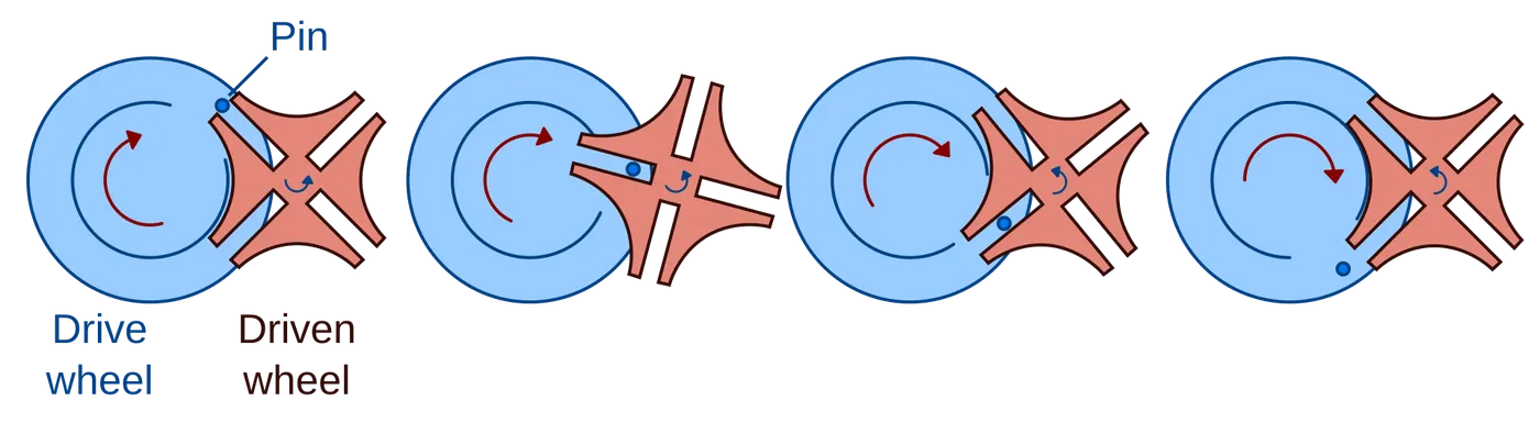
The rotating drive wheel is usually equipped with a pin that reaches into a slot located in the other wheel (driven wheel) that advances it by one step at a time. The drive wheel also has an elevated circular blocking disc that "locks" the rotating driven wheel in position between steps. Mechanisms is shown below.
Applications:
One application of the Geneva drive is in film movie projectors and movie cameras, where the film is pulled through an exposure gate with periodic starts and stops. The film advances frame by frame, each frame standing still in front of the lens for a portion of the frame cycle (typically at a rate of 24 cycles per second), and rapidly accelerating, advancing, and decelerating during the rest of the cycle. This intermittent motion is implemented by a Geneva drive, which in turn actuates a claw that engages sprocket holes in the film. The Geneva drive also provides a precisely repeatable stopped position, which is critical to minimizing jitter in the successive images. (Modern film projectors may also use an electronically controlled indexing mechanism or stepper motor, which allows for fast-forwarding the film.
Process:
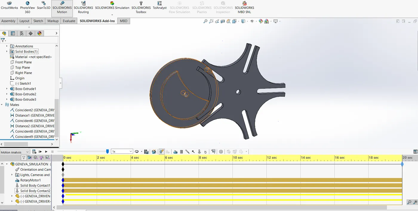
- Create 3D model in solidworks using 2d Drawing file as shown below.
- Create assembly of both Driver and driven wheel.
- Apply constraints.
- Start motion study at 10 rpm anstant speed.
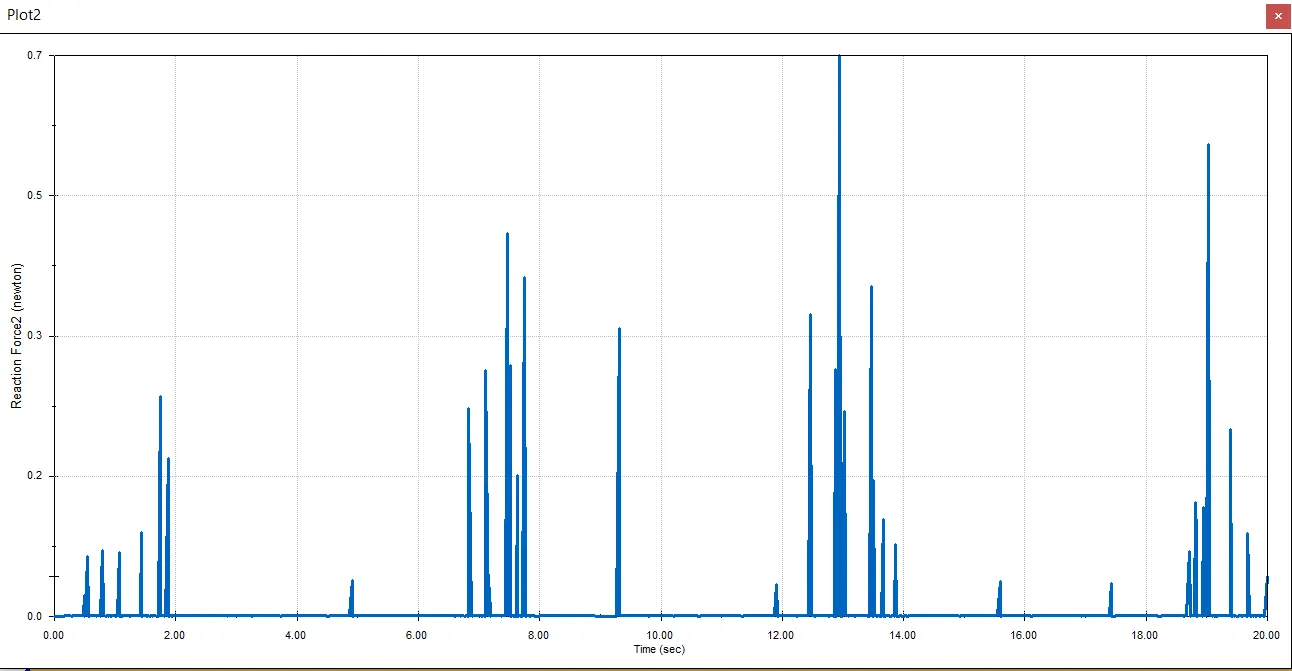
Contact force vs time graph.
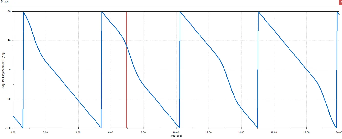
Angular displacement vs time graph
Conclusion:
- The contact force is always maximum when the pin and the slot contact each other. After that the force almost zero because the driven wheel rotate freely due to initial force by pin and slot.
Youtube video Link: