Internal Geneva Mechanism
AIM:
Design the Internal Geneva Mechanism and perform the Motion analysis of it for different cases.
OBJECTIVE:
- Create 3D models for driver and driven wheels.
- Perform motion analysis by rotating the driver wheel at 10 rpm for 1st study and at 20rpm for another case.
- Obtain the results for Contact Force (between driving and the driven wheel) as a function of time, angular displacement of the driven wheel & then driver wheel’s angular velocity with and without “Precise Contact”
INTRODUCTION:
The Geneva is one of the earliest of all intermittent motion mechanisms and when input is the form of a
Continuous rotation, it is probably the most commonly used. They are cheaper than cams or star wheels and have adequate to good performance characteristics, depending on load factors and other design requirements.
They come in variety of sizes having a good motion-curve characteristics but exhibit more jerk or instantaneous change in acceleration. It maintains good control of its load at all times. If properly sized to the load, it generally exhibits very long life. But it is not a versatile mechanism.
Applications of Geneva Mechanism:-
- The common application of Geneva Drive is Movie Projectors.
- Wrist Watches
- Plotters- it is a computer printer used for printing vector graphics
- Automated sampling machines
- Bank Note Counting Machine.
Types of Geneva drives are:
- Spherical Geneva Drive
- External Geneva Drive
- Internal Geneva Drive
An Internal Geneva drive is a variant on the design. The axis of the drive wheel of the internal drive can have a bearing only on one side. The angle by which the drive wheel has to rotate to effect one step rotation of the driven wheel is always smaller than 180 degree in an External Geneva Drive and always greater than 180 degree in an internal one, where the switch time is therefore greater than the time the driven wheel stands still.
THEORY:
The Geneva drive is a gear mechanism that translates a continuous rotation movement into intermittent rotary motion. The rotating drive wheel is usually equipped with a pin that reaches into a slot located in the other wheel (driven wheel) that advances it by one step at a time. The drive wheel also has an elevated circular blocking disc that “locks” the rotating driven wheel in position between steps.
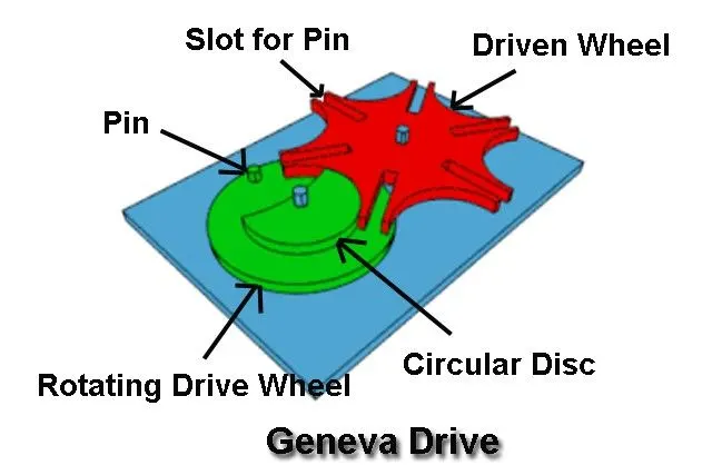
The main difference between Geneva drive and other gears is that Geneva drive have unusual teeth. Unlike other gears ,in Geneva drive the interaction between the driving and the driven part is not continuous and the resultant motion is intermittent.
In Geneva drive there are two wheels, driving and driven wheel. The driving wheel has a pin and a little more than semi circular disc which is elevated. The driven wheel has 4, 6 or more slots in which the pin of driving wheel passes and rotates the driven wheel to angle depending upon number of slots. If it has 4 slots, it will be rotated 90 degrees in one step and if it has 6 slots, it will be rotated 60 degrees at one step. The circular elevated disc is used to lock the driven wheel after each step.
PROCEDURE:
- Create a 2D sketch of the Driven wheel as per the given dimensions and then converted into 3D part model and save it as part file.
- Create a 2D sketch of the Drive wheel of Internal Geneva as per the given dimensions and then convert it into 3D part model and save it as part file.
- Open a new life as assembly part file and import both the parts of Internal Geneva i.e. the driver wheel and the driven wheel.
- Using various mates assemble the Internal Geneva’s driving wheel with the driven wheel as need and also, at a certain distance from the center to center of each wheel axis.
- Save the assembled file separately and open it in a new window for motion analysis.
- Start with the motion study setup, select the motion analysis and then set the various parameters for it.
- Add motor to the driver wheel at its center axis with certain rpm, initially 10rpm
- Add solid contact face for the mechanism that is Driver and the driven wheel with a material respectively.
- Calculate the contact force between driver and the driven wheel by selecting its face and showing the plots the results.
Also, select the angular displacement option for driven wheel and angular velocity for driven wheel respectively. - Set the frame as 60 for 10rpm motor initially and then 120 frames for 20rpm motor with and without precision contact.
- Select the calculate option and then start the animation to get all the final results.
SETUP:-
2D SKETCH:-
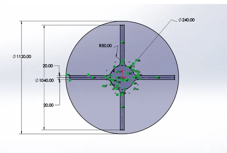
The above image shows the 2D sketch with certain dimensions for internal Geneva driven wheel.
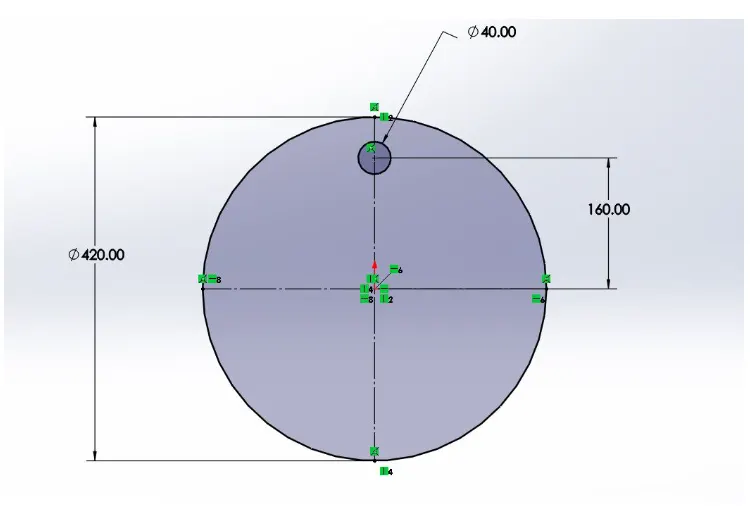
The above image shows the 2D sketch with certain dimensions for internal Geneva driver wheel.
3D MODEL:-
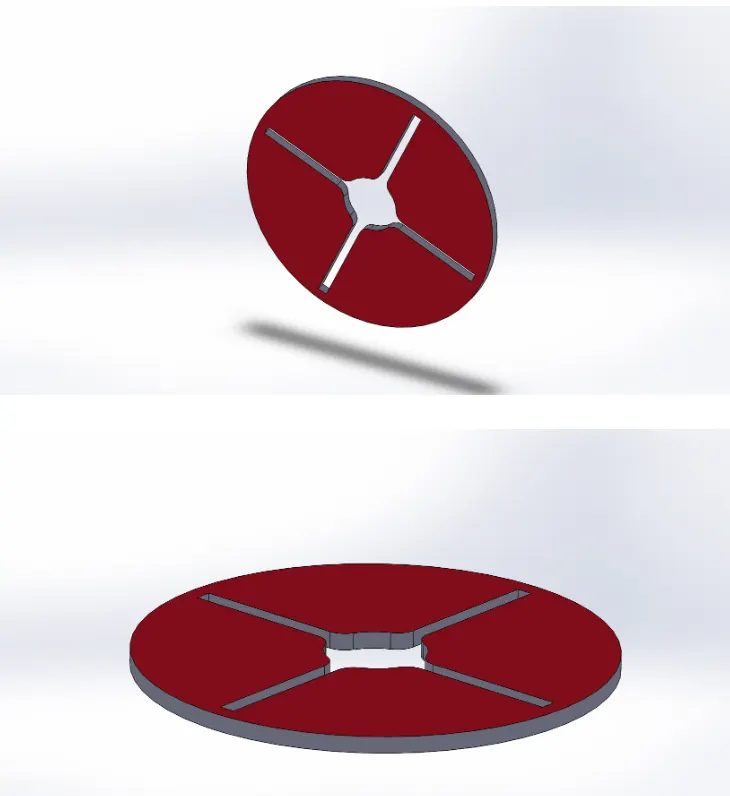
The 2D sketch of Driven wheel is converted into 3D sketch using extrude command from features of 40mm thickness. The above 2 images show the complete part model for the Driven wheel.
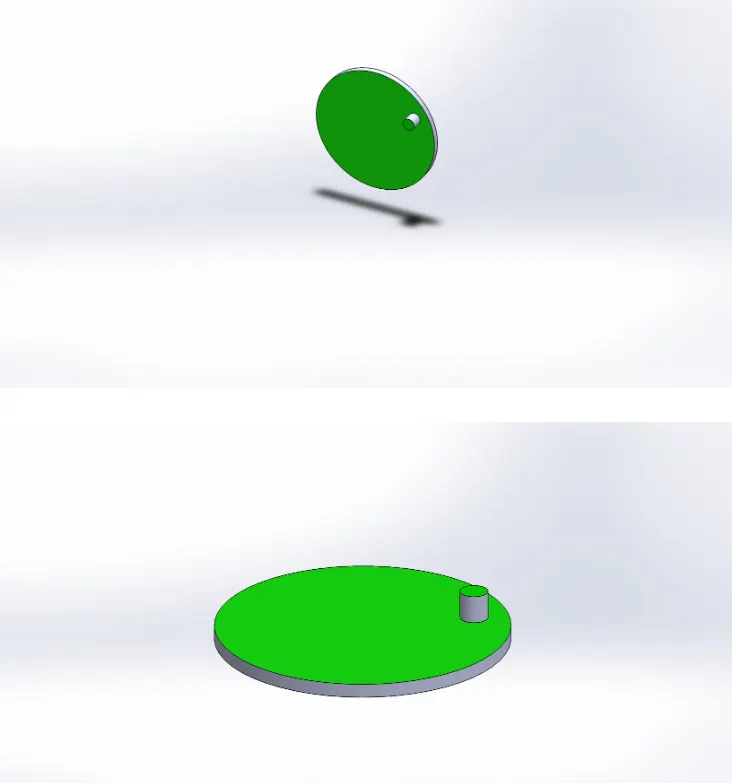
The 2D sketch of Driver wheel is converted into 3D sketch using extrude command from features of 20mm disc and 40mm pin thickness. The above image shows the complete part model for Driver wheel.
ASSEMBLY:
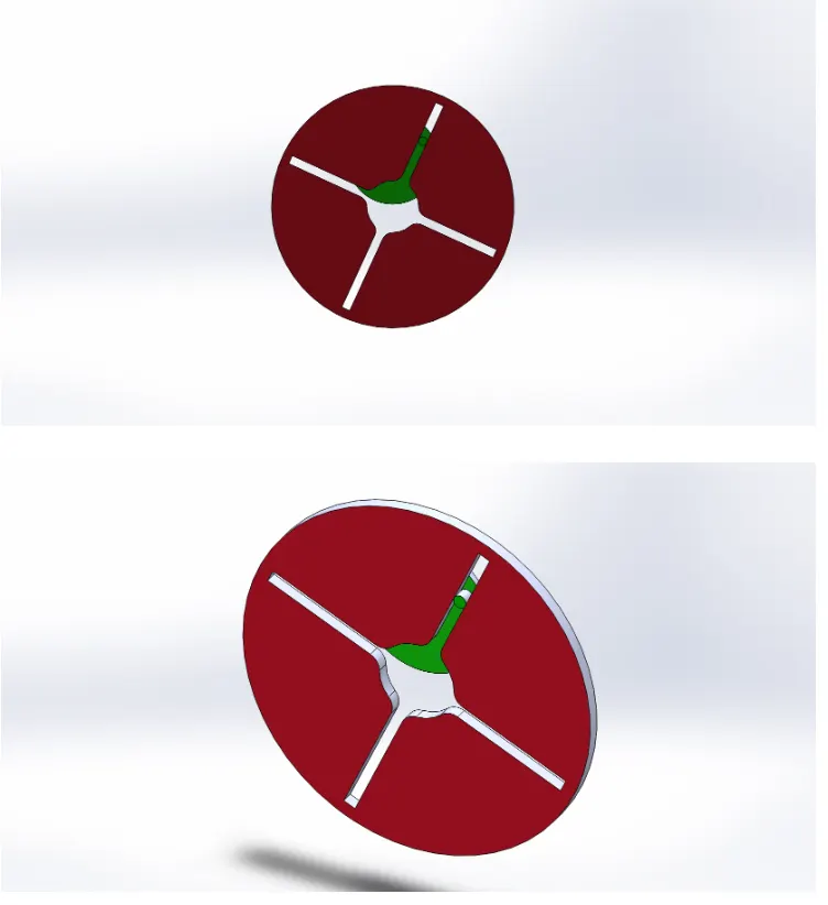
The two part models driver wheel and driven wheel are assembled using various mates. The above 2 images represents the front view and diametric view of internal Geneva mechanism by assembled driver and driven wheel.
MOTION STUDY SETUP:
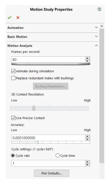
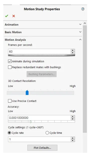
- Select the motor and axis of the driver wheel with setting the various parameters like rpm, frame, precision, etc.
- Apply solid contact between 2 wheels with materials.
- Run the motion analysis and get the calculated results.
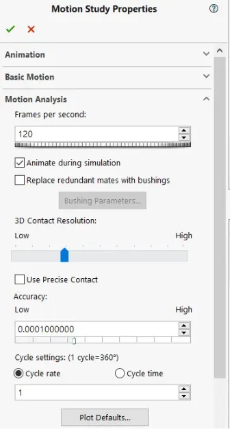
In analysis setup 1st case is done for non-precise contact and then for precise contact. The above images shows the motion study properties for 10rpm motor initially, without precision and next analysis setup with precise contact with 60 fps for both the cases.
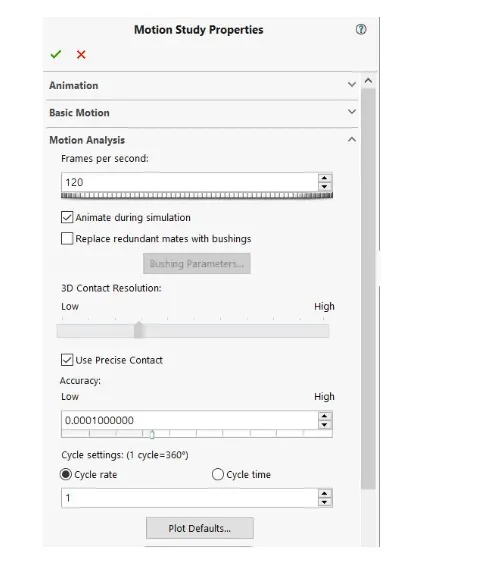
In the above analysis setup 1st case is done for non-precise contact and then for precise contact. The above images shows the motion study properties for 20rpm motor initially, without precision and next analysis setup with precise contact with 120 fps for both the cases.
RESULTS:
Normal results for 10 rpm motor with 25fps with non-precise contact.
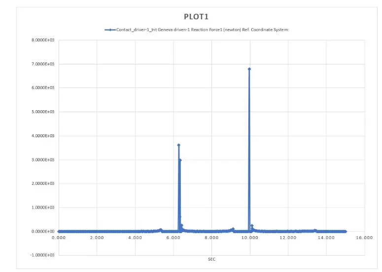
The plot above shows the Contact force with time between driver and the driven wheel for 10 rpm motor with 25fps as an initial start.
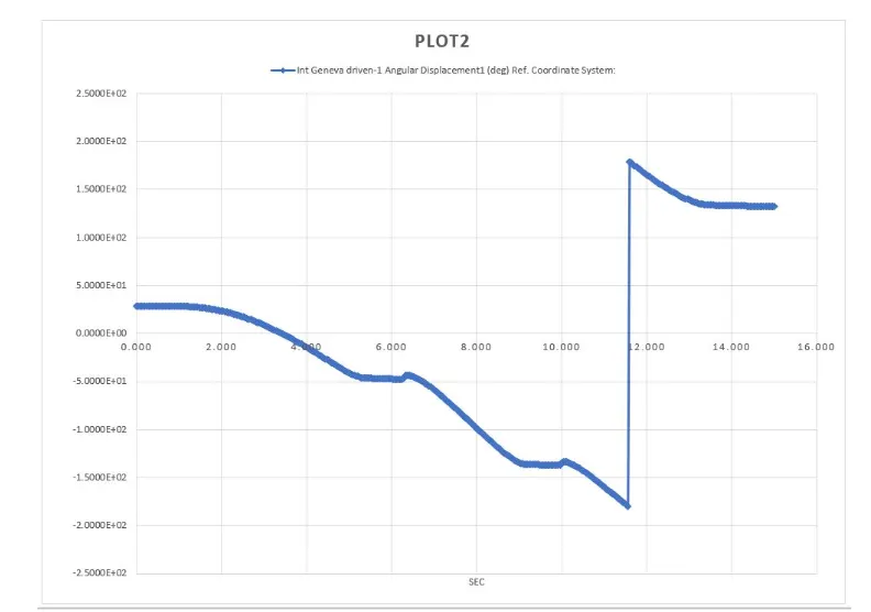
The plot above shows the angular displacement for driven wheel with time for 10rpm motor with 25 fps. It shows the variation for angular displacement with respect to time.
OUTPUT for 10rpm motor (without precise contact)
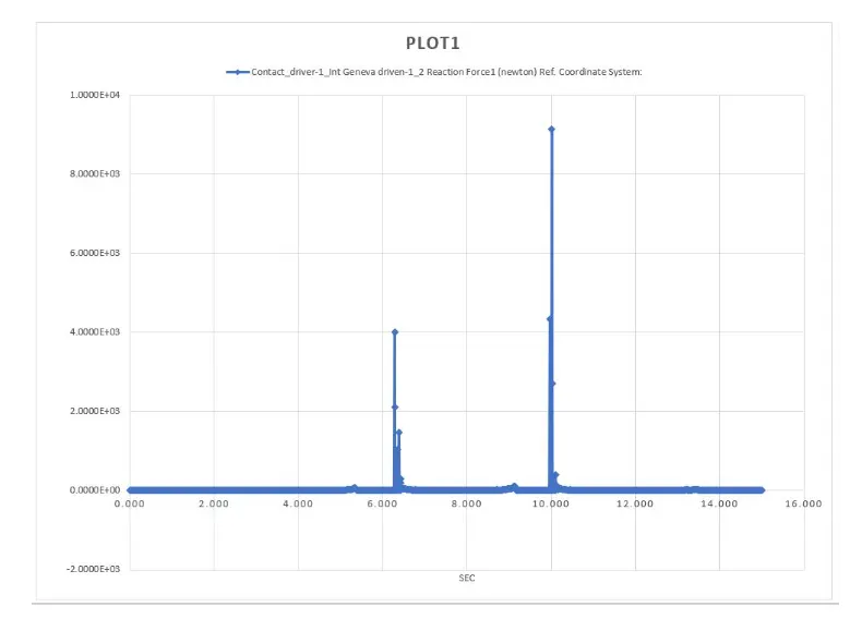
The above image shows the plot for a motion of rotating motor of 10 rpm with 60 fps non-precise contact. The plot represents the contact force between driver and the driven wheel on Y axis vs the time taken in sec on X axis respectively.
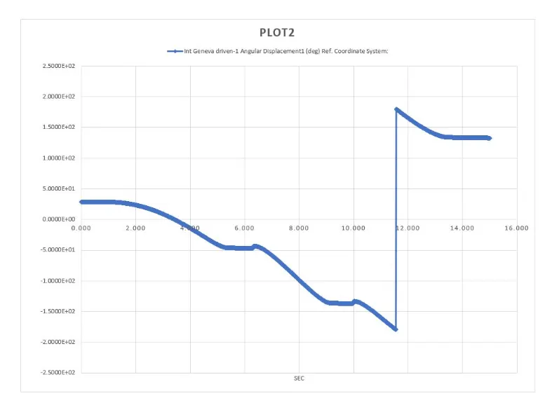
The above plot represents the angular displacement for driven wheel on Y axis vs the time taken on X axis respectively. It is the plot for a motion of rotating motor of 10 rpm in clockwise direction with 60 frame per second as a non- precise contact.
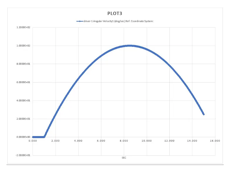
The above plot represents the angular velocity ford river wheel on Y axis vs the time taken in sec on X axis respectively. It is the plot for a motion of rotating motor of 10 rpm in clockwise direction with 60 frame per second as a non- precise contact.
OUTPUT For 10rpm motor (with precise contact)
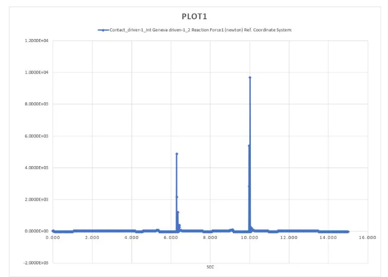
The above image shows the plot for a motion of rotating motor of 10 rpm with 60 fps precise contact. The plot represents the contact force between driver and the driven wheel on Y axis vs the time taken in sec on X axis respectively.
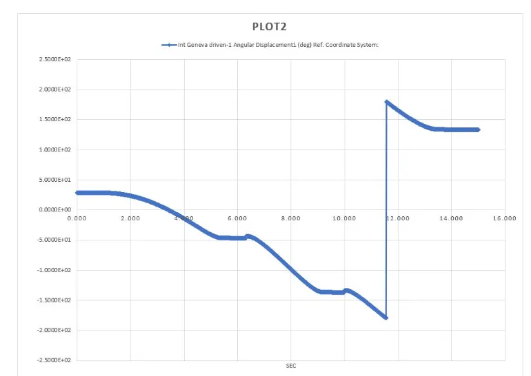
The above plot represents the angular displacement for driven wheel on Y axis vs the time taken in sec on X axis respectively. It is the plot for a motion of rotating motor of 10 rpm in clockwise direction with 60 frame per second as a precise contact.
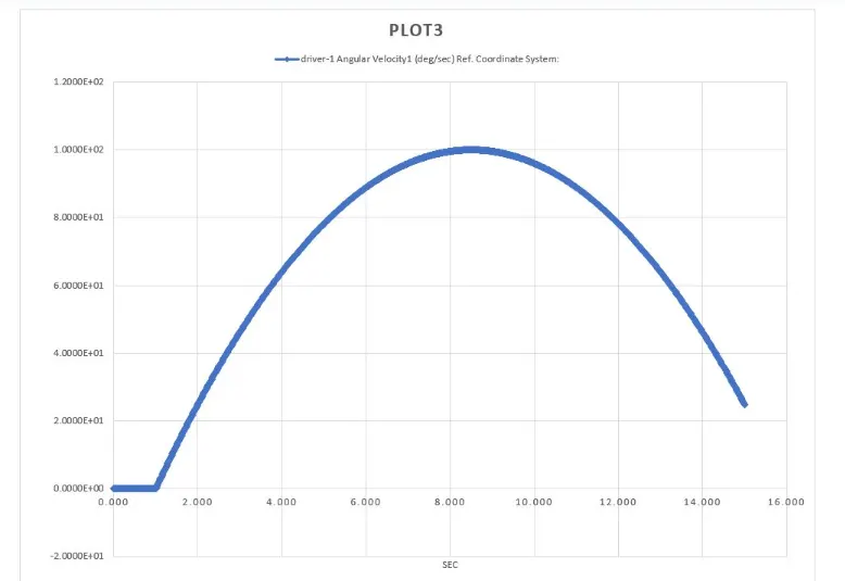
The above plot represents the angular velocity for driver wheel on Y axis vs the time taken on X axis respectively. It is the plot for a motion of rotating motor of 10 rpm in clockwise direction with 60 frame per second as a precise contact.
OUTPUT For 20rpm motor(without precise contact)
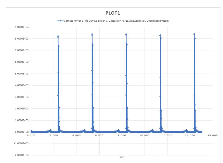
The above graph shows the plot for a motion of rotating motor of 20rpm with 120 fps non-precise contact. The plot represents the contact force between driver and the riven wheel on Y axis vs the time taken in sec on X axis respectively.
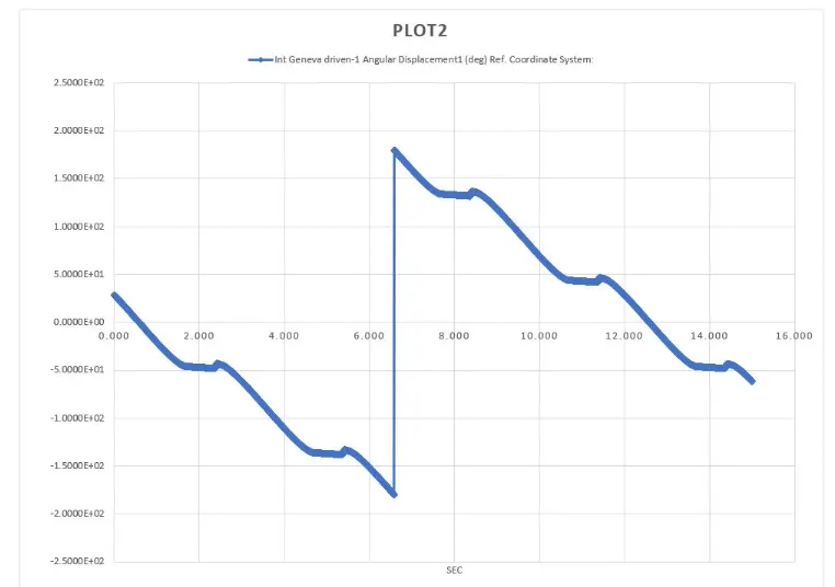
The above plot represents the angular displacement for driver wheel on Y axis vs the time taken in sec on X axis respectively. It is the plot for a motion of rotating motor of 20rpm in clockwise direction with 120 frames per second as a non-precise contact.
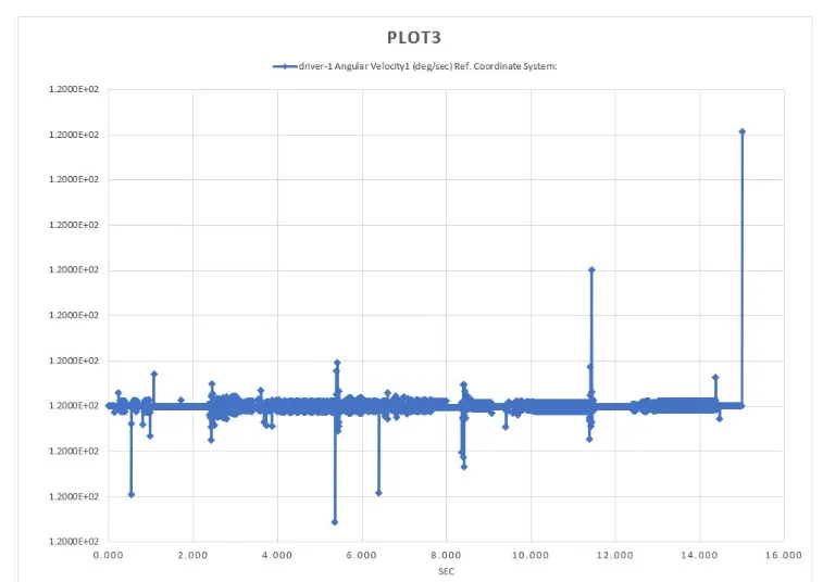
The above plot represents the angular velocity for driver wheel on Y axis vs the time taken in sec on X axis respectively. It is the plot for a motion of rotating motor of 20 rpm in clockwise direction with 120 frame per second as a non-precise contact.
OUTPUT For 20rpm motor (with precise contact)
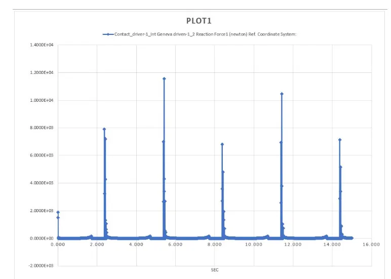
The above graph shows the plot for a motion of rotating motor of 20 rpm with 120 fps precise contact. The plot represents the contact force between driver and the driven wheel on Y axis vs the time taken in sec on X axis respectively.
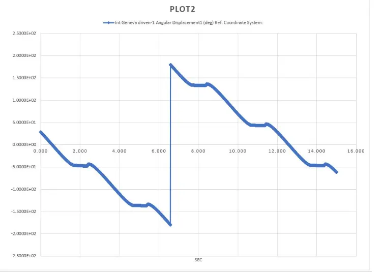
The above plot represents the angular displacement for driven wheel on Y axis vs the time taken in sec on X axis respectively. It is the plot for a motion of rotating motor of 20 rpm in clockwise direction with 120 frame per second as a precise contact.
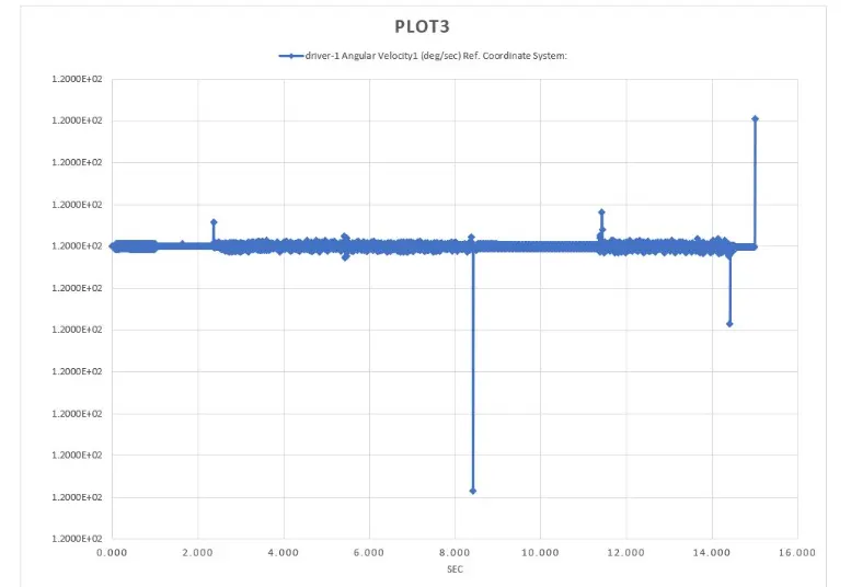
The above plot represents the angular velocity for driver wheel on Y axis vs the time taken in sec on X axis respectively. It is the plot for a motion of rotating motor of 20 rpm in clockwise direction with 120 frame per second as a precise contact.
OBSERVATION:
The results for the motion analysis shows the various plots for contact force with or without precise contact in which the maximum contact force with respect to time is seen in the plot for 20 rpm motor with precise contact as compared to others. When the rpm of motor with precise contact as compared to others. When the rpm of motor increases thus, the angular displacement of driven wheel also increases. Precise contact indicates more contact force than non-precise from graph generated for motion analysis.
CONCLUSION:
We had briefly understood the fundamentals of Internal Geneva mechanism and its working by performing motion analysis in SolidWorks using a MBD tool. Also, we had designed the mechanism parts i.e. driver and the driven wheel, assembled and conducted its motion analysis for 2 different rotating speed of motor i.e. for 10 and 20 rpm respectively.
ANIMATION:-
Motion Analysis animation for Internal Geneva Mechanism for 10 rpm without precise contact
Motion Analysis for Internal Geneva Mechanism for 20 rpm without precise contact-
Motion Analysis for Internal Geneva Mechanism for 20 rpm with precise contact-
REFERENCES
https://www.britannica.com/technology/Geneva-mechanism