Internal Geneva Mechanism
AIM :
- To create the 3D models of the driver and driven wheels of the internal Geneva mechanism.
- To perform motion analysis by rotating the driver wheel at 10rpm and to obtain the following plots :
1.Contact force (between driving and the driven wheel) as a function of time
2.Angular Displacement of the driven wheel.
- To compare the contact forces with and without "Precise contact" with supporting plots.
- To make a plot of the driver wheel's angular velocity by rotating the driver wheel at 20 rpm.
- To discuss the above mentioned plots and results in detailed manner.
Internal Geneva Mechanism :
1.What it is ? : The Geneva mechanism translates a continuous rotation into an intermittent rotary motion. The rotating drive wheel has a pin that reaches into a slot of the driven wheel.In an internal Geneva drive the axis of the drive wheel of the internal drive is supported on only one side.
An internal Geneva drive is a variant on the design. The axis of the drive wheel of the internal drive can have a bearing only on one side. The angle by which the drive wheel has to rotate to effect one step rotation of the driven wheel is always smaller than 180° in an external Geneva drive and always greater than 180° in an internal one, where the switch time is therefore greater than the time the driven wheel stands still.
2.Where it is used ? : Pen change mechanism in plotters, automated sampling devices, banknote counting machines, and many forms of indexable equipment used in manufacturing (such as the tool changers in CNC machines; the turrets of turret lathes and turret drills; some kinds of indexing heads and rotary tables; and so on).
Working mechanism :
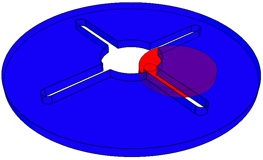
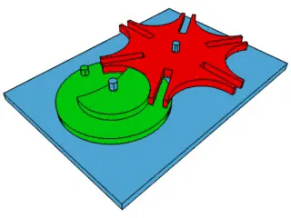
INTERNAL GENEVA MECHANISM EXTERNAL GENEVA MECHANISM
METHODOLOGY :
3D Modelling :
2D Drawing
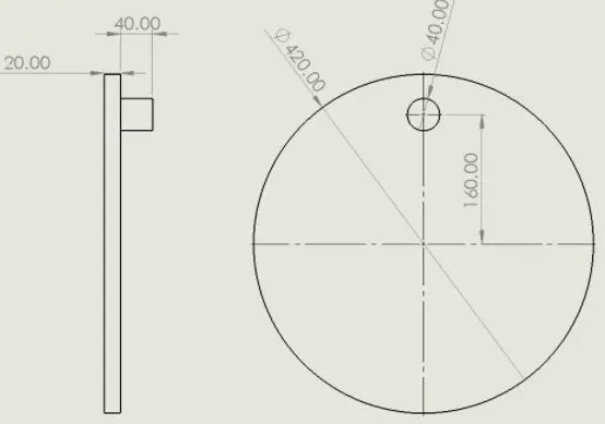
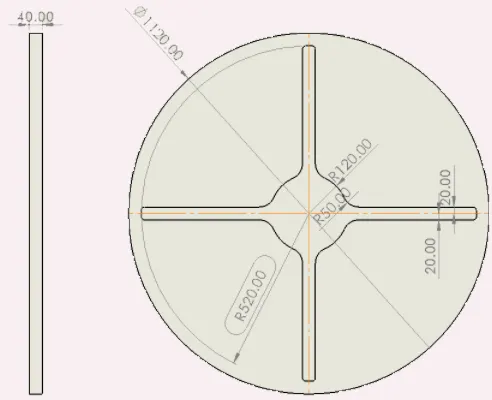
Driver Wheel Driven Wheel
The driver wheel is the component to which the motor is coupled and generates the rotary motion.The extrusion(small shaft) present in driver wheel moves along the driven wheel's slot to translate the motion.
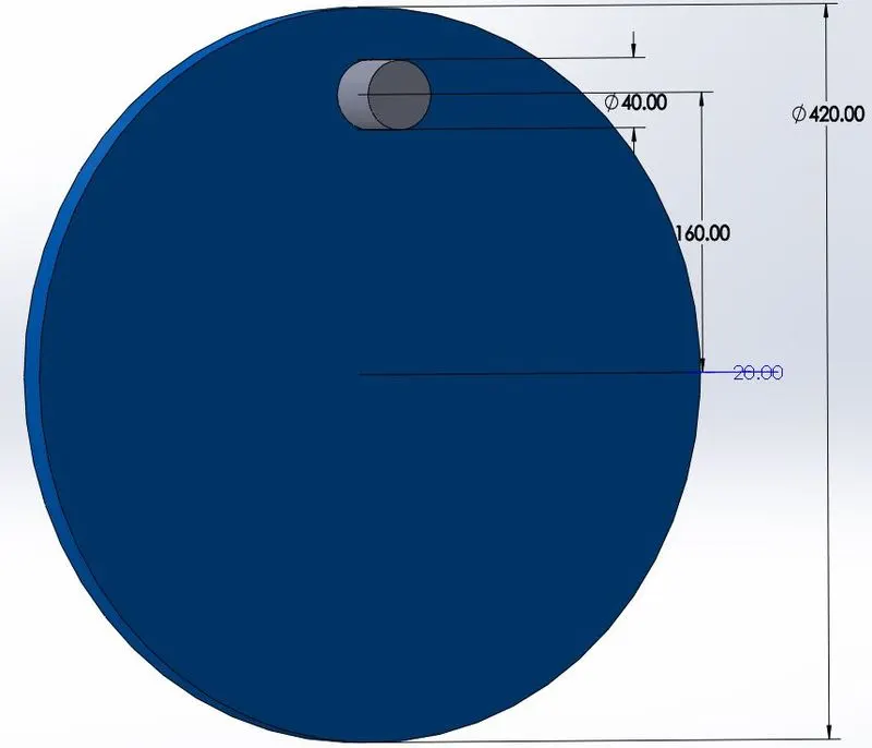
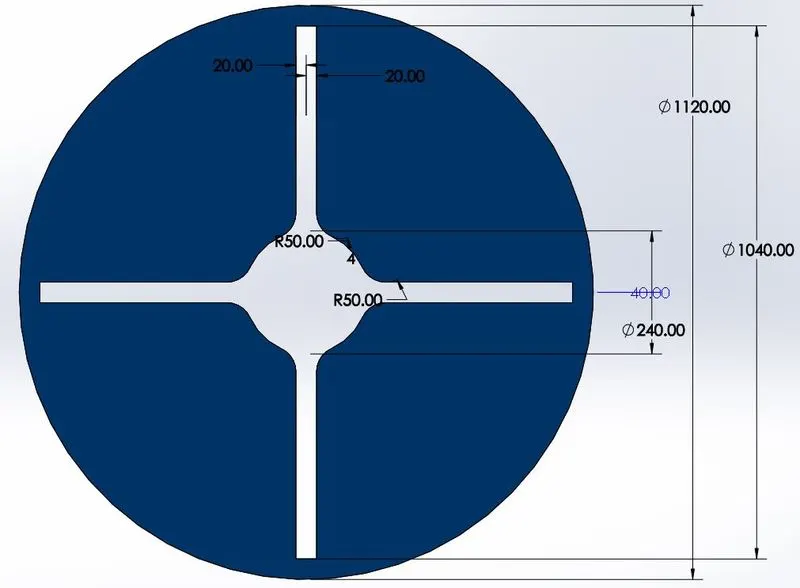
3D- DRIVER WHEEL 3D- DRIVEN WHEEL
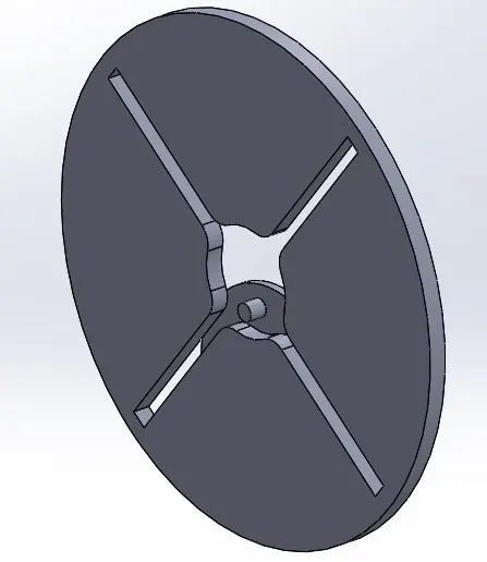
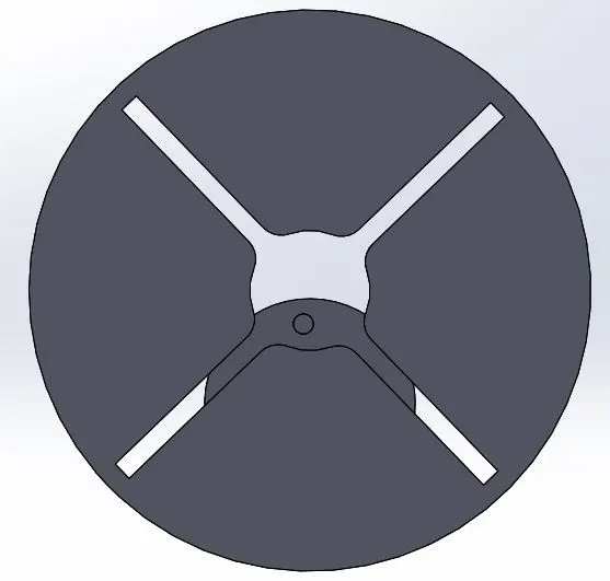
Assembled view of driver and driven wheels.
Software used : Solidworks 2018.
TOOLS USED :
SKETCH : Circle,line,fillet,offset
FEATURES :Extrude
3D model the drive and driven wheels using the mentioned tools and assemble it by providing the constraints such that both the wheels can only be rotated(not be able to move in either direction).
MOTION ANALYSIS:
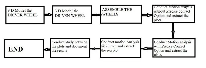
After assembling the parts, conduct motion analysis by the following steps :
Click SOLIDWORKS Add-Ins > Select SOLIDWORKS Motion > Move back to Assembly tab & select New Motion Study
ANALYSIS 1 :
1. Select the Motion Analysis option in the dropdown present in left bottom .
2. Click the motor icon and then select rotor type,In component/direction option select the axis of the driver wheel,
select the motion type as Constant speed and set rpm as 10 .
3. Click the contact icon > select solid Bodies type > In selections select the drive and driven wheels > In materials select dry steel for both the options(it can be changed as per your choice).
4. Then in time frame select till 20 secs and conduct motion anaysis.
5. Extract the plots by selecting the Results/Plots option.
6.To extract the plot contact force (btw Driver and driven wheel) Vs Time follow the steps mentioned :
Select the Results/Plots option > Select the forces in the category > select the Contact forces in sub-Category > Select the magnitude in result component > select the driver and driven wheels > click the tick mark. Plot will be displayed.
7. To extract the plot of Angular displacement of the driven wheel follow the steps mentioned :
Select the Results/Plots option > Select the displacement/velocity/Acceleration option in the category > select the Angular displacement in sub-Category > Select the magnitude in result component > select the driven wheel > click the tick mark. Plot will be displayed.
ANALYSIS 2 :
1. Select the Motion Analysis option in the dropdown present in left bottom .
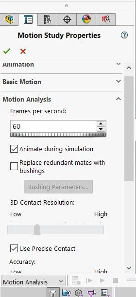
2.In the settings option select the Use precise contact option and set the frames per second as 60.
3. Click the motor icon and then select rotor type,In component/direction option select the axis of the driver wheel,
select the motion type as Constant speed and set rpm as 10 .
4. Click the contact icon > select solid Bodies type > In selections select the drive and driven wheels > In materials select dry steel for both the options(it can be changed as per your choice).
5. Then in time frame select till 20 secs and conduct motion anaysis.
6. Extract the plots by selecting the Results/Plots option.
7.To extract the plot contact force (btw Driver and driven wheel) Vs Time follow the steps mentioned :
Select the Results/Plots option > Select the forces in the category > select the Contact forces in sub-Category > Select the magnitude in result component > select the driver and driven wheels > click the tick mark. Plot will be displayed.
8. To extract the plot of Angular displacement of the driven wheel follow the steps mentioned :
Select the Results/Plots option > Select the displacement/velocity/Acceleration option in the category > select the Angular displacement in sub-Category > Select the magnitude in result component > select the driven wheel > click the tick mark. Plot will be displayed.
ANALYSIS 3 :
1. Select the Motion Analysis option in the dropdown present in left bottom .
2. Click the motor icon and then select rotor type,In component/direction option select the axis of the driver wheel,
select the motion type as Constant speed and set rpm as 20 .
3. Click the contact icon > select solid Bodies type > In selections select the drive and driven wheels > In materials select dry steel for both the options(it can be changed as per your choice).
4. Then in time frame select till 20 secs and conduct motion anaysis.
5. Extract the plots by selecting the Results/Plots option.
6. To extract the plot of Angular velocity of the driver wheel follow the steps mentioned :
Select the Results/Plots option > Select the displacement/velocity/Acceleration option in the category > select the Angular velocity in sub-Category > Select the magnitude in result component > select the driver wheel > click the tick mark. Plot will be displayed.
ANALYSIS 4 :
1. Select the Motion Analysis option in the dropdown present in left bottom.
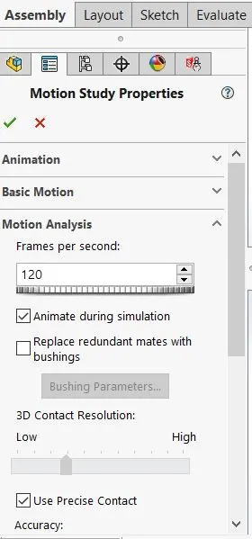
2.In the settings option select the Use precise contact option and set the frames per second as 120.
3. Click the motor icon and then select rotor type,In component/direction option select the axis of the driver wheel,
select the motion type as Constant speed and set rpm as 20 .
4. Click the contact icon > select solid Bodies type > In selections select the drive and driven wheels > In materials select dry steel for both the options(it can be changed as per your choice).
5. Then in time frame select till 20 secs and conduct motion anaysis.
6. Extract the plots by selecting the Results/Plots option.
7. To extract the plot of Angular velocity of the driver wheel follow the steps mentioned :
Select the Results/Plots option > Select the displacement/velocity/Acceleration option in the category > select the Angular velocity in sub-Category > Select the magnitude in result component > select the driver wheel > click the tick mark. Plot will be displayed.
RESULTS AND CONCLUSION:
1.Contact Force (between Driver & Driven wheel) Vs Time
RPM : 10 rpm
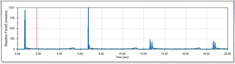
Contact Force (Between Driver and driven wheels) Vs Time (Without selecting the Use precise contact option)
RPM : 10 rpm
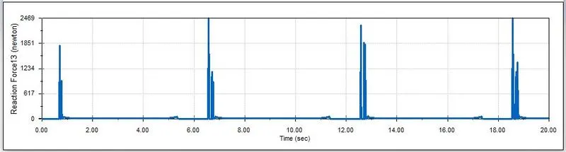
Contact Force (Between Driver and driven wheels) Vs Time (selecting the Use precise Contact option)
In both the first plot the contact force (between the driver and driven wheels) is at peaks when the small extrusion in the driver wheel enters the slot in the driven wheel.The same case is appicable to second plot (where the analysis is conducted with precise contact option selected).
By comparing the plots , the observations are :
The magnitude of the maximum contact force is higher in the second plot (2469 N max) than the first plot (1301 N max).
In plot 1,the contact force had peaks and troughs while in plot 2 the contact forces are almost nearer to each other.
In plot 1, The magnitude of the contact forces at 1,7,13,19 secs are 1275N,1301 N,325N,300N and its corresponding range is 975N while in plot 2 the values are 1800N,2469N,2400N,2469N and it corresponding range is 669N.
Since the range is lower in plot 2, we can obtain the nearest results by using the Use precise contact option.
The magnitude of the peaks occuring at 1,7,13,19 secs is lower at first plot than the second plot.So,by selecting the Use precise contact option, the nearest contact force can be obtained , which can be used for further design improvement.
So, by using the Use precise contact option, the nearest Contact force can be obtained.
2.Angular Displacement of the driven wheel Vs Time
RPM : 10 rpm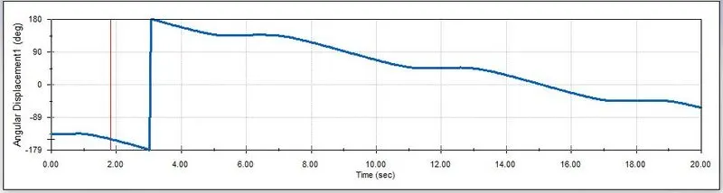
Angular displacement of the driven wheel Vs Time (Without selecting the Use precise contact option)
RPM : 10 rpm
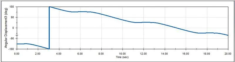 Angular displacement of the driven wheel Vs Time (Selecting the Use precise contact option)
In both the plots the angular displacement of the driven wheel is -45 deg at 0 sec and -117.5 deg at 20 secs and steeper at 3secs where the driven wheel moves faster.
By comparing both the plots , the Angular displacement of the driven wheel remains the same in both the analysis,so the use precise contact option has no effect on Angular displacement of the driven wheel.However ,it can be used to get a clear plot because the representation of angular displacement at 3 secs is vertical line which is little scattered in plot1 compared to plot 2.
3.Angular Velocity of the driver wheel Vs Time
RPM : 20 rpm
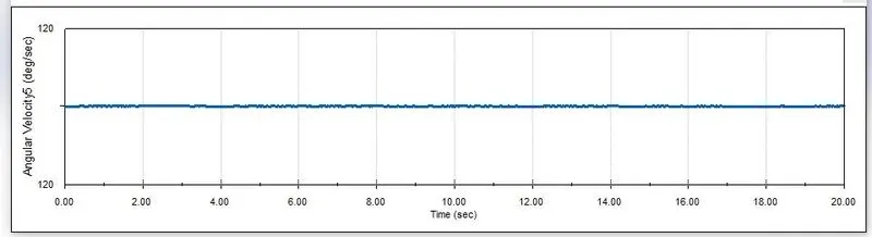
Angular velocity of the driver wheel Vs Time (Without selecting the Use precise contact option)
RPM : 20 rpm
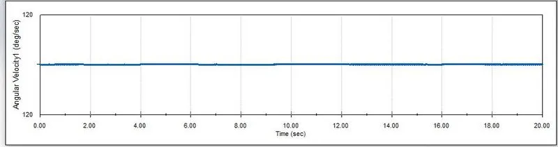
Angular velocity of the driver wheel Vs Time ( selecting the Use precise contact option)
In both the plots, Angular velocity of the driver wheel remains constant with respect to time. By comparing the both plots,the use precise contact option has no effect on Angular velocity of the driver wheel .However ,it can be used to get a clear plot because the representation of angular displacement at 3 secs is vertical line which is little scattered in plot1 compared to plot 2.
So, by conducting the motion anaysis with Use precise contact option activated ,the most nearest results can be obtained which can be used for further design improvements and modifications to achieve maximum efficiency.