Internal Geneva Mechanism
Multibody Dynamics of Internal Geneva Mechanism using Solidworks
Abstract
Software used is Solidworks
In this Project, Creating a 3D part of Driver and Driven from scratch and will be setting up the motion analysis for an Internal Geneva Mechanism at 10rpm and 20rpm with 60 frames and 120 frames respectively. Then obtaining the plots of Contact force (between driving and the driven wheel) as a function of time, Angular Displacement of the driven wheel, and plot of the driver wheel's angular velocity.
1. Introduction
1.1 Multibody Dynamics
(MBD) system is one that consists of solid bodies, or links, that are connected to each other by joints that restrict their relative motion. The study of MBD is the analysis of how mechanical systems move under the influence of forces, also known as forwarding dynamics.
1.2 Geneva Mechanism
The Geneva drive or Maltese cross is a gear mechanism that translates a continuous rotation movement into intermittent rotary motion.
The rotating drive wheel is usually equipped with a pin that reaches into a slot located in the other wheel (driven wheel) that advances it by one step at a time. The main wheel also has an elevated circular blocking disc that "locks" the rotating driven wheel in position between steps.
There are basically Three types of Geneva mechanism
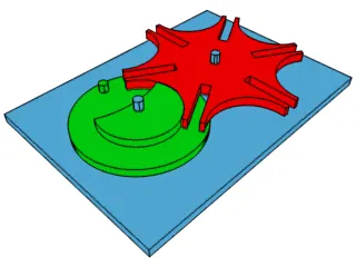
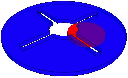
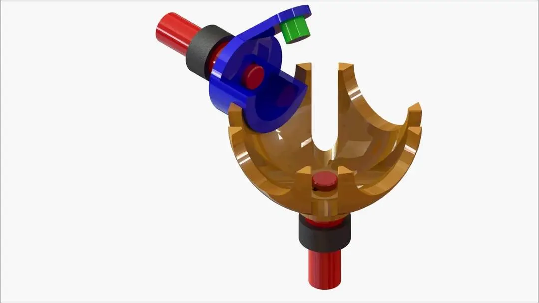
1.3 Contact Force
A contact force is any force that requires contact to occur.[1] Contact forces are ubiquitous and are responsible for most visible interactions between macroscopic collections of matter. Pushing a car up a hill or kicking a ball or pushing a desk across a room are some of the everyday examples where contact forces are at work.
1.4 Angular Displacement
Angular displacement of a body is the angle in radians (degrees, revolutions) through which a point revolves around a centre or line has been rotated in a specified sense about a specified axis. When a body rotates about its axis, the motion cannot simply be analyzed as a particle, as in circular motion it undergoes a changing velocity and acceleration at any time (t). When dealing with the rotation of a body, it becomes simpler to consider the body itself rigid. A body is generally considered rigid when the separations between all the particles remain constant throughout the body's motion, so for example parts of its mass are not flying off. In a realistic sense, all things can be deformable, however, this impact is minimal and negligible. Thus the rotation of a rigid body over a fixed axis is referred to as rotational motion.
The Present study is to analyze the motion study of an internal geneva mechanism and plot various graphs and compare the plots and explain the results.
Geometry and Modelling
The internal Geneva Mechanism consist of three parts
1)The Driven Wheel
2)The Driver or the Crank
3)The pin
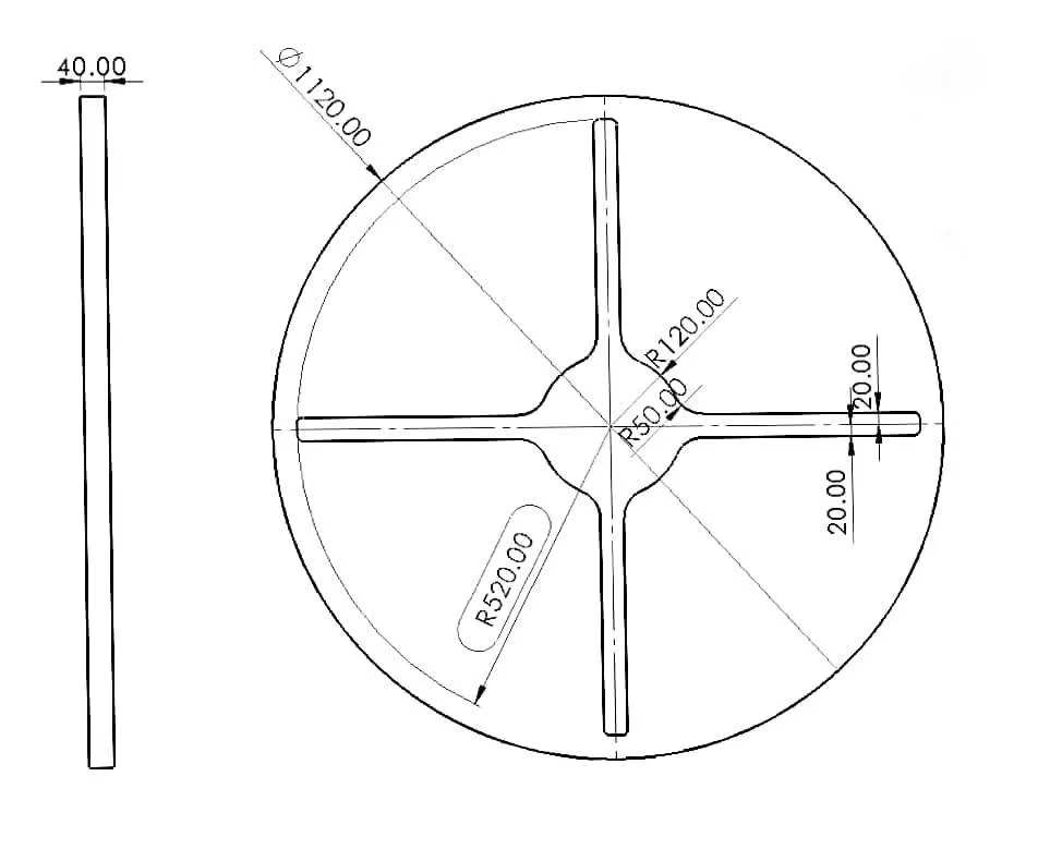
To do the motion analysis of the internal Geneva Mechanism we need to first design the parts in solidWorks and assemble them according to the 2D drawing
Driver part:
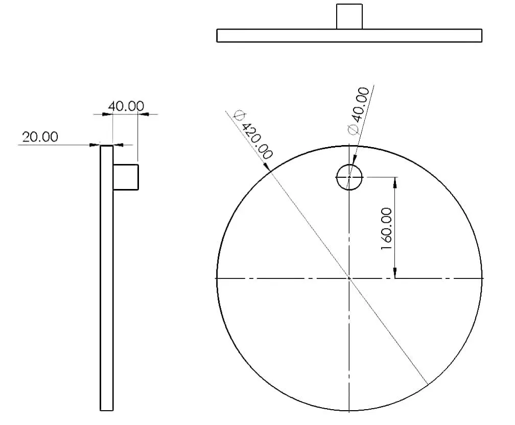
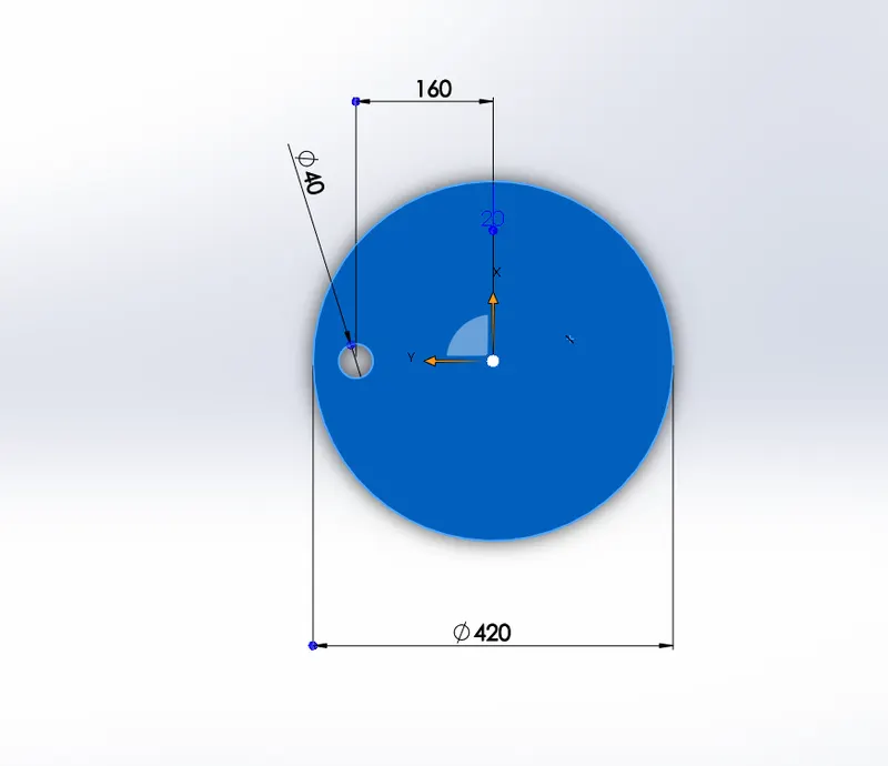
We are going to design our first part which is Driving wheel based on 2D drawing. first select front plane and choose the option for sketching, draw a circle at Axis with diameter 420-millimetre diameter, similarly draw a small circle with diameter 40 millimetres and at a distance of 160 mm from the centre.
After completing 2D sketching we are going to use the Extrude option. to make the 2D drawing into 3D. Extrude Larger circle and smaller circle with 20 mm and 40 mm respectively, the final result of the first part is as shown below.
Driven part:
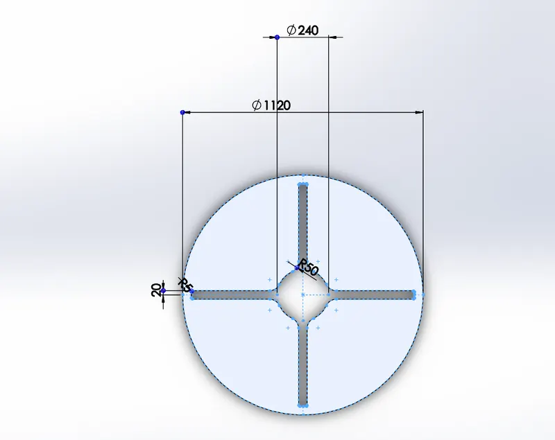
our second part is driven part which is known as Driven wheel. again we are going to use front playing as a sketching plane. now Drawing a circle with diameter 1120. our driving wheel has slots for moving part of driver wheel. hence to draw a slot in the driven wheel we are going to draw x and y-axis as a reference.
Using offset with
after that, we are going to draw Internal circle with radius 120 millimetre
which has Fillet of the 50-millimetre radius.
Extruding with 40 millimetres.
The Pin
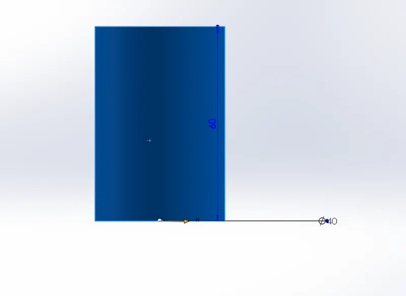
The Pin connects the Driver and the Driven Part
Assembly Design:
To do motion analysis we are going to assemble the parts which we are designed previously. for more convenient we are using part 1 name for driving wheel and part 2 name for the driven wheel. first, we are going to open a new file and select assembly by taking the unit in consideration
Now, we are importing two parts in an assembly.
Note:- the first part imported is always fixed to free it to right-click on Part-1 and click on float option, now we can move our part in our required direction. after that, we are going to use mate option to constrain or part.
we are going to select temporary Axis visible for more convenient in assembly. now we can see many axes in our parts. we are selecting a front plane of part-1 and assembly and choose to coincide option. another way to do that we can choose mate option in assembly and selecting a front plane of assembly and front plane of part-1
select Centre axis of part 1 and consider with write plane of assembly, similarly, we are going to coincide the centre axis of Part 1 with the top plain of assembly.
now we can see that our part 1 is fully constrained it can do only circular motion at its own axis.
further, we are going to a constraint our second part. to do that we are considering its Axis with the right plane of assembly and coinciding it. now we can see that our part is in line with part 1 but it still required proper constraint. hence we are going to find out the centre distance between part 1 and part 2 which is unknown to us, hence we are taking the approximate distance between the parts.
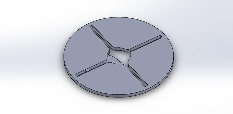
3.4 Simulation and Analysis:
To do simulation and analysis (i.e motion analysis) we are going to choose the Solidworks motion option from Solidworks Add-Ins. now we can see that the motion analysis option which is shown below in the window of Solidworks.
To Rotate the Driving wheel we are going to assign motor for driving wheel. to do that select motor option in motion analysis and select part 1 axis. after that, we are going to assign solid body contact by selecting contact option and selecting part 1 and part 2. from Menu we can assign a material to the parts.
To analyse multiple parameters, we can use a plot option in motion analysis, the plot results as follows.
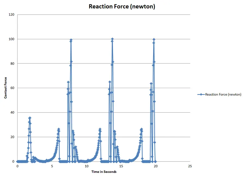
Analysis at 10Rpm and 25 frame
Contact Force between the Driver and the Drivern Wheels
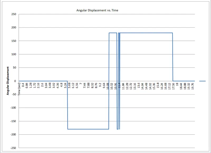
Angular Displacement of the Driven Wheel at 25 frame and 10rpm
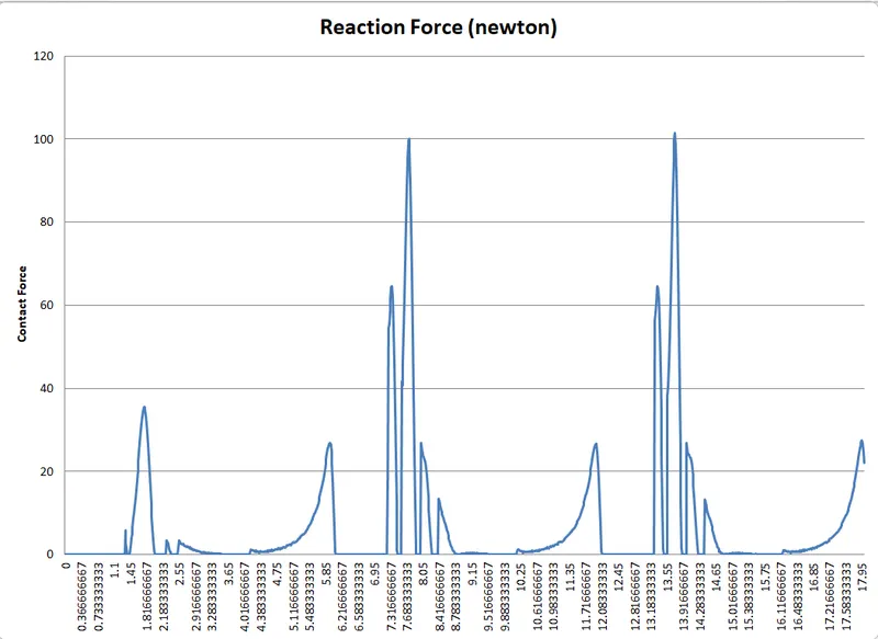
Contact Force with Precise contact
10rpm and 60 frames
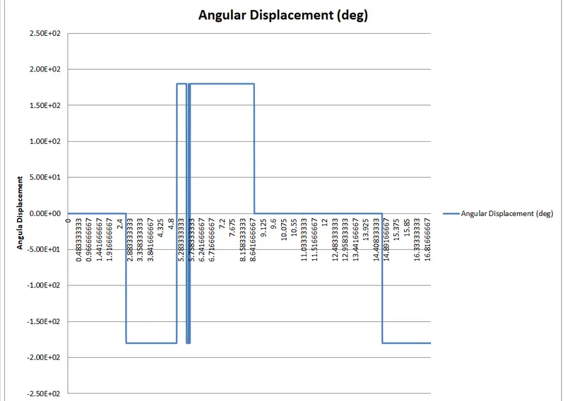
Angular Displacement at 10rpm and 60 frames of the Driven Wheel
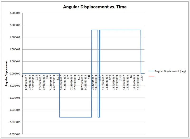
Contact Force at 20Rpm and 120 frames
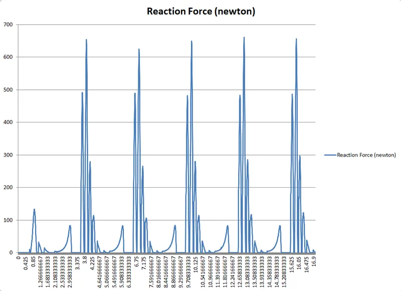
Angular Displacement at 20rpm and 120 frames of the Driven Wheel
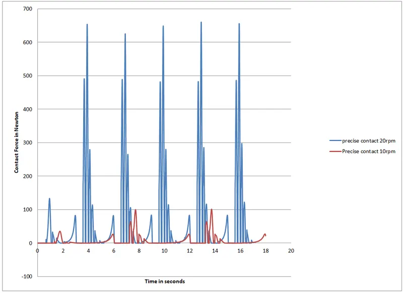
Comparision Contact Force at 10rpm and Contact Force at 20rpm
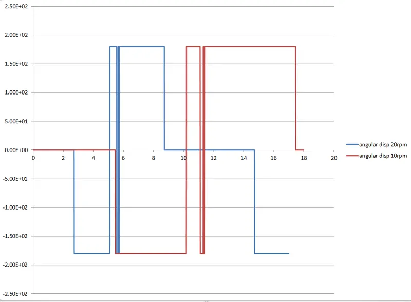
Comparison between Angular Displacement at 20rpm and Angular displacement at 10rpm of the Driven Wheel
Error & error elimination:-
The common error we can get during the motion analysis is the jerk.
The first cause of jerk is due to improper alignment of the driven wheel and drive wheel. This may cause serious damage to the real-life situation. Hence to avoid this error we need to align the drive and driven wheel by changing the centre distance between them.
The second cause of jerk is due to low rpm of the motor. Because gravity is acting on the driven wheel the small distortion in the position of the drive wheel occurs. hence, the key is unable to insert in the slot smoothly. To avoid that we can increase the rpm of the motor or set up our assembly arrangement in such a way that the gravity effect is zero.
Note:- Always Remember the unit system while doing part design and Assembly Design.
Result and Conclusion
Video showing the motion Analysis at 10rpm and 60 frames
Video shows the motion analysis at 20rpm and 120frames
1)In The contact force graph at 20 and 10 rpm where we got a peak in the graph at a different point because when the pin of driver moves inside the driven member slot some jerk occurs in between the pin and the slot of the driven wheel,also the peak observed in the 20rpm graph is more as compared to the 10rpm graph
2)The graph for angular displacement at 10rpm and angular displacemet at 20rpm is being obtained and is observed that angular displacement being a function of angular velocity and time ,more the angular velocity less time it takes to cover the distance as it is clearly visible from the graphs ,one more observation is being made irrespective of the rpm the maximum and the minimum angular displacement coverd by the mechanism is the same.
3)In the video above and also from the graphs it is clearly visible that more the angular velocity the jerk observed at the entry of pin in the slot of the driven wheel is more.
4)As observed from the graphs as the frames increased we are able to calculate more precise results.
5.2 Conclusion:
Plots for the contact force and angular displacement at 10rpm and 20rpm is obtained and the results are discussed