Induction motor characteristics
INDUCTION MOTOR CHARACTERISTICS
OBJECTIVE:
- To explain how induction motor operation is similar to cutch.
- Calculate the starting time of a drive with the given parameters.
- For the given torque equation obtain the equilibrium points and determine the stability of the vehicle.
EXPLANATION:
1)Induction Motor:
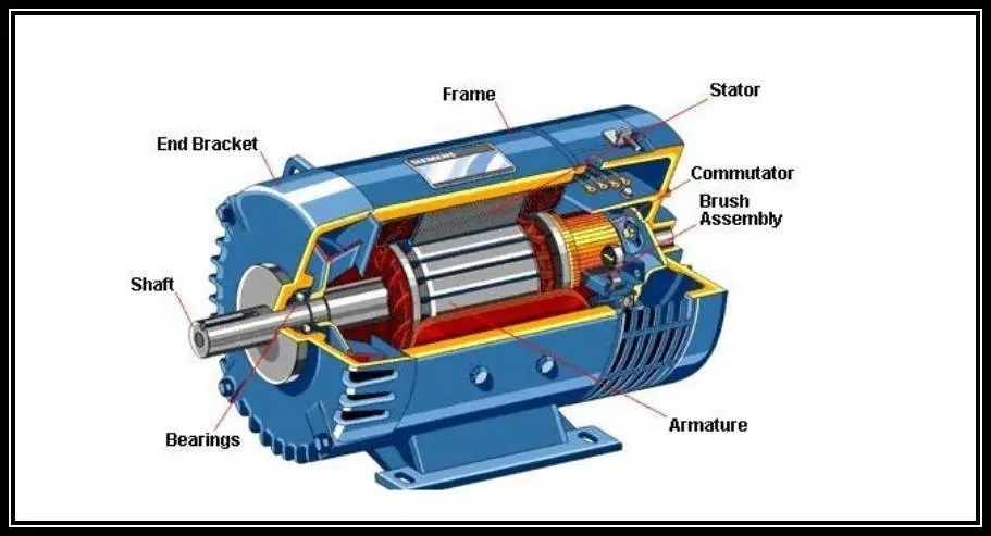
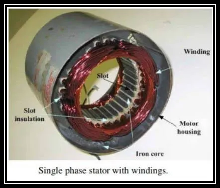
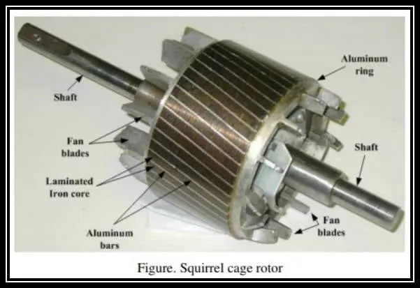
An induction motor (also known as the asynchronous motor ) is a commonly used AC electric motor. In an induction motor, the electric current in the rotor needed to produce torque is obtained via electromagnetic induction from the rotating magnetic field of the stator winding. The rotor of an induction motor can be a squirrel cage rotor or Wound type rotor.
Induction motors are referred to as 'Asynchronous motors' because they operate at a speed less than their synchronous speed. Synchronous speed is the speed of rotation of the magnetic field in a rotary machine, and it depends on the frequency and number of poles of the machine. The induction motor always runs at a speed less than its synchronous speed.
The Rotating magnetic field produced in the stator will create flux in the rotor, hence causing the rotor to rotate. Due to the lag between the flux current in the rotor and the flux current in the stator, the rotor will never reach its rotating magnetic field speed.
TYPES:
- There are basically two types of induction motor.
- The types of induction motors depend upon the input supply.
- There are single-phase induction motors and three-phase induction motors.
- Single-phase induction motors are not self-starting motor and three-phase induction motors are a self-starting motor.
OPERATION:
- The input supply is given to the stator winding, a magnetic flux gets produced in the stator due to the flow of current in the coil.
- The rotor winding is arranged in a manner that each coil becomes short-circuited.
- The flux from the stator cuts the short-circuited coil in the rotor.
- As the rotor coils are short-circuited, according to Faraday's law of electromagnetic induction, the current will start flowing through the coil of the rotor.
- When the current through the rotor coils flows another flux gets generated in the rotor.
- Now there are two fluxes, one is stator flux and another is rotor flux.
- The rotor flux will be lagging with respect to the stator flux.
- Because of that, the rotor will feel a torque which will make the rotor to rotate in the direction of the rotating magnetic field.
- This is the working principle of both single and three-phase induction motors.
- The synchronous speed can be calculated by using the formula:
- Ns=`(120f)/p`
- f=supply frequency,
- p=Number of poles.
- The difference between the synchronous speed and the rotor speed is the slip.
- Slip(S)=`(Ns)-(Nr)`
where,
Ns=synchronous speed.
Nr=Rotor speed.
- Usually, the slip is denoted in percentage,
- Slip(S)=`((Ns)-(Nr))/(Ns)`
- From the above equation, the motor speed can be calculated as follows:
Nm=`Ns(1-S)`
CLUTCH:
- The Clutch is the most important part of the engine in the automobile.
- A clutch uses to transfer rotating motion or torque from one shaft to another shaft when requires.
- The torque developed by the engine at the initial speed is very low.
- Therefore it is impossible to start the engine under load.
- It requires that the transmission system should provide a means of connecting and disconnecting the engine from the rest of the transmission system.
- Such an operation must be smooth and without shock to the passenger of the vehicle.
- The Clutch is located between the engine and gearbox.
- During normal running and stationary position, it is always in the engaged position.
- The clutch disengages when the driver presses the clutch pedal.
- The clutch disengages for starting, changing gears, stopping, and idling.
- When the clutch engages the engine will connect to the transmission and power flows from the engine to the rear wheels through a transmission system.
- When the clutch disengages the power will not transmit to the wheels.
PRINCIPLE:
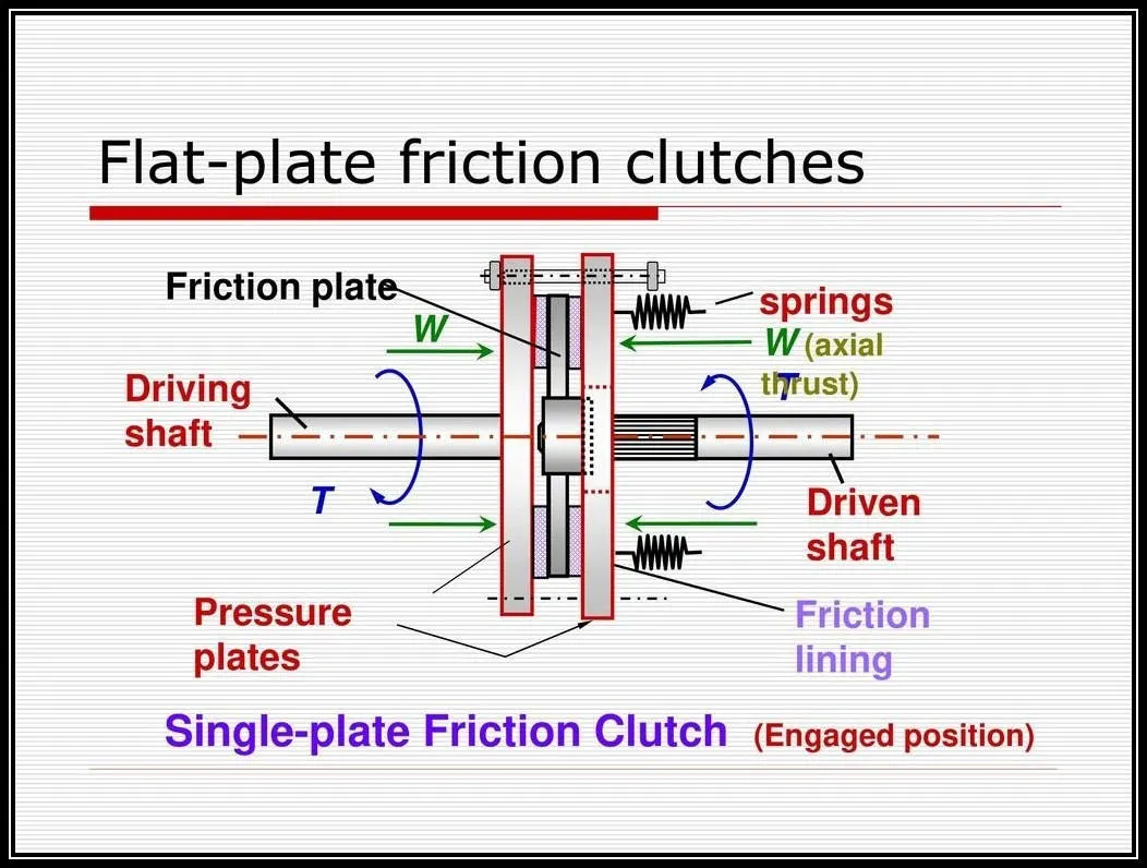
- The clutch works on the principle of friction.
- In fig, the driving shaft A with flange C is rotating at 'N' rpm, and shaft B with the flange D is keyed to the driven shaft which is in a stationary position when the clutch is not engaged. Now, an external force is applied to the flange D so that it comes in contact with the flange C.
- As soon as the contact is made, they are united due to friction between them and the flange D starts rotating with flange C.
- The rotational speed of flange D depends on the friction between surfaces C and D which in turn is proportional to the external force applied.
- If the force gradually increases, the speed force transmitted will also increase gradually. The torque transmitted by the friction clutch depends on the pressure applied on the flange, coefficient of the surface materials, and radius of the flange. By increasing any of them, the force transmitted can increases.
- Consider N1 is the speed of the driving shaft and N2 be the driven shaft speed.
- The driven shaft speed can be calculated by using the formula:
N2=N1(1-s).
N1=driving shaft speed.
N2=driven shaft speed.
s=slip
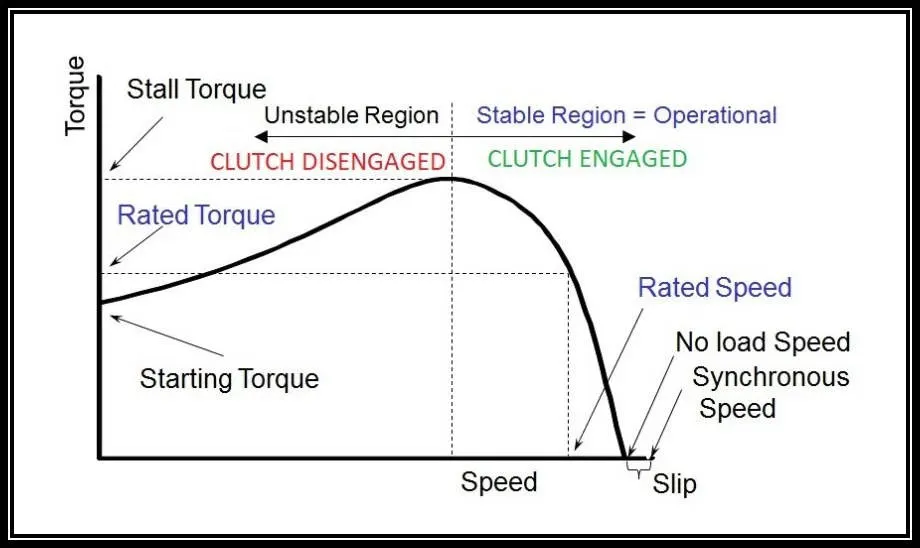
- From the above equation, we may infer that both the induction motor and the clutch will have similarities in operation.
2)Calculate the Starting time of a drive:
Reference:https://skill-lync.com/knowledgebase/calculating-starting-time-for-induction-motor-3
The above article is referred for calculating the starting time.
GIVEN:
J=10 kg-m2.
T = 15 + 0.5wm.
Tl=5+0.6ωm.
TO FIND:
Starting time.
SOL:
- Initially, the motor torque and load torque are equated for the steady-state conditions in order to obtain the speed.
- Then, the time taken for the drive to change the speed from one`omega1` to another `omega2` can be given by the equation:
`dt=(J*domegam)/((Tm*(omegam))-(Tl(omegam)))`
- The above equation is integrated to find the starting time.
- The integral limits should be considered from the initial condition of the motor to the end of the transient state after which the motor attains its steady-state speed. So we consider the limits as 0 to 95.
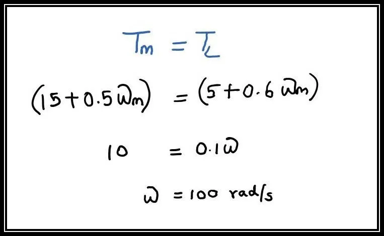
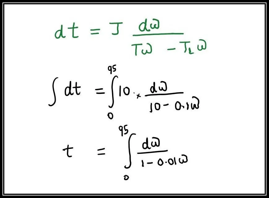
- To integrate the above equation, we use Matlab to find out the answer.
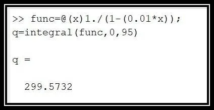
- On integrating the above equation we get the starting time to be around 299.57sec.
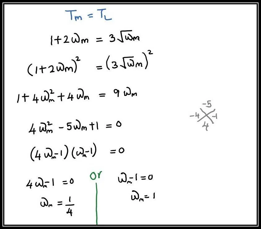
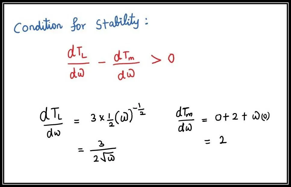
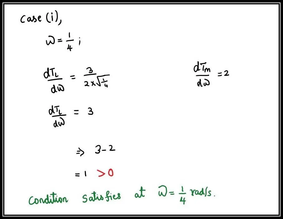
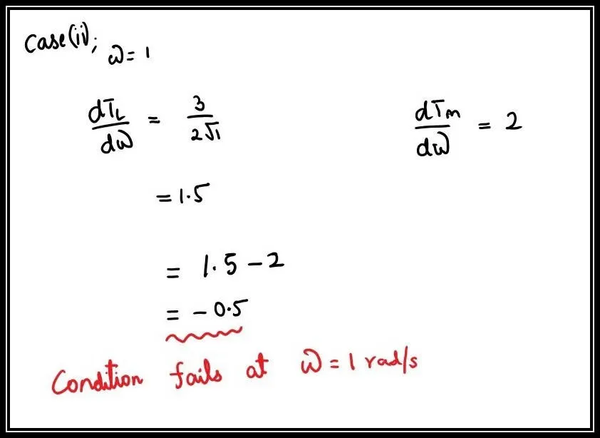
3)To determine the equilibrium points and determine the stability.
GIVEN:
Tm=(1+2ωm)
Tl= 3 √ωm
Sol: