Independent Research Project
AIM:
To simulation of fluid flow a through pipe.
OBJECTIVE:
- Flow through pipe simulation for fluid of particular properties.
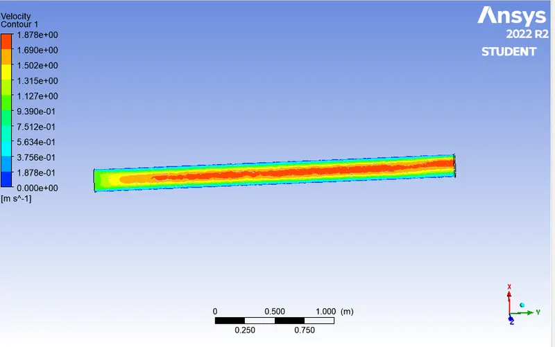
- Calculate the velocity contours are find out laminar flow through pipe.
INTRODUCTION:
Fluid flow a through pipe:
- Fluid flow describes how fluid behaves when in motion.
- It is a vital engineering perspective and studied in hydraulics and fluid mechanics. #
- The theory of fluid flow is very important for effectively sizing piping and equipment.
Fluid
Any substance which can flow is called fluid. Liquids, gases, or a mixture of both of them are collectively called fluids. They contain a finite mass, occupy a space, and are tangible. They are substances which either made up of different molecules or particles. They are flowing when the particles of the substance have a change in the relative position concerning time. The properties acquired by the fluids are
- It does have a mass of its own.
- It doesn’t have shapes.
- It occupies the shape of the vessel or pipe where it is flowing.
- It can flow under its weight.
Mechanics is the study of force and its effects. The forces that act on the fluid are
- Surface force
- Body force ( gravitational force)
Fluid Flow Inside Pipeline
- Flow-through pipes or fluid flow is a type of flow within a closed conduit with a certain pressure. Another type of flow is an open channel flow.
- These fluid flows are applied to transport chemicals, petroleum products, gas products, sewage flows, household water supply, etc. in different piping and pipeline systems.
- The flow of all Real fluids is termed viscous flow( as they possess a viscosity) These properties of viscosity are characterized by the shear stresses or the frictional forces between the fluid layers and fluid to a solid surface, same as the physical parameters of the pipe & the external force’s affecting the piping system by displacement and loads. T
- he fluid’s flowing and the flow parameters affect the piping system in many ways.
Flow Rate Through Pipes
- The flow rate (discharge) is termed as the volume of the fluid which passes per unit time, through the pipes.
- ie, area of pipe*velocity at which fluid flows through the pipe (unit-m3/s).
Type of Fluid
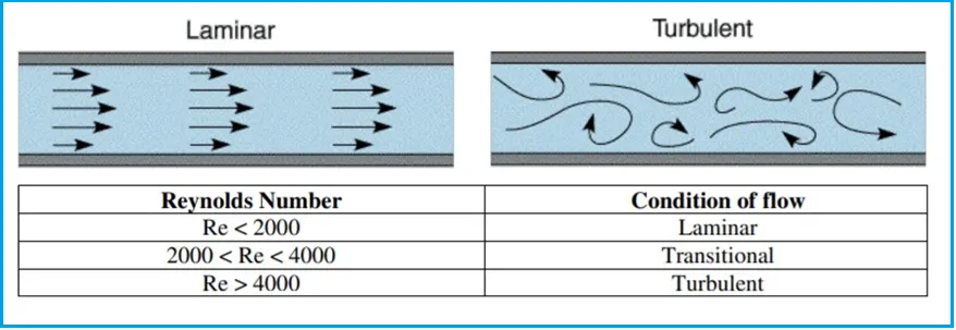
- The two types of flow through a pipe can be classified as laminar or turbulent flow.
- The non-dimensional number, Reynolds number (Re), is used to determine the type of flow-through pipes.
Laminar flow:
- When the fluid moves slowly in layers in a pipe, without much mixing among the layers.
- usually occurs when the velocity is low / the fluid is very viscous.
- The maximum flow will be at the center of the pipes and the minimum flow at the pipe walls.
(Refer to the Fig. 1 below)
Turbulent Flow:
- When the velocity of the flow exceeds some threshold value for a given fluid in a pipe, ie. when the velocity is high.
- flow becomes turbulent, the fluid becomes irregularly fluctuating with time.
- Velocity at the center of the pipe is approximately equal to the average flow velocity.
Modelling Approach :
GEOMETRY:
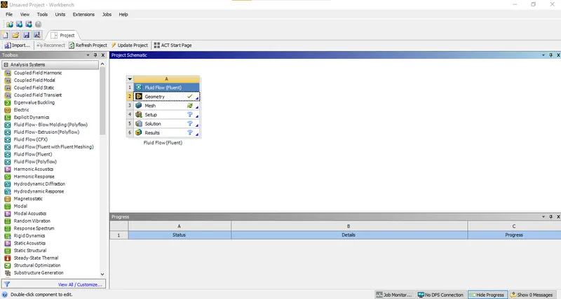
- Open ANSYS Workbench 2022R2 select Fluid Flow (Fluent) from Toolbox.
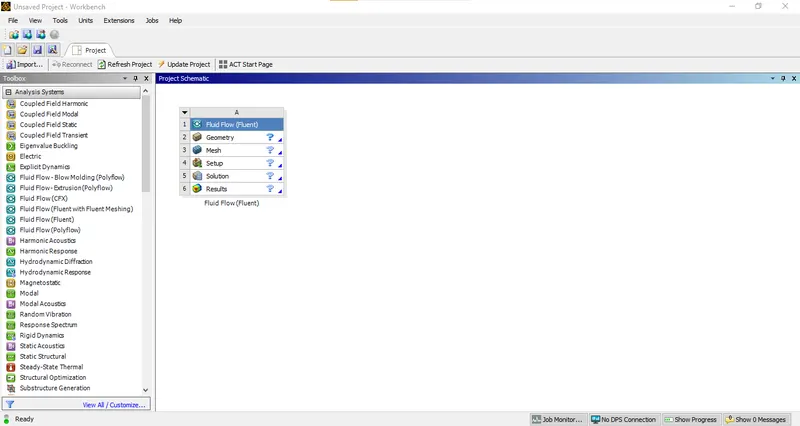
- Rename the file and left click Geometry and select New Spaceclaim Geometry.
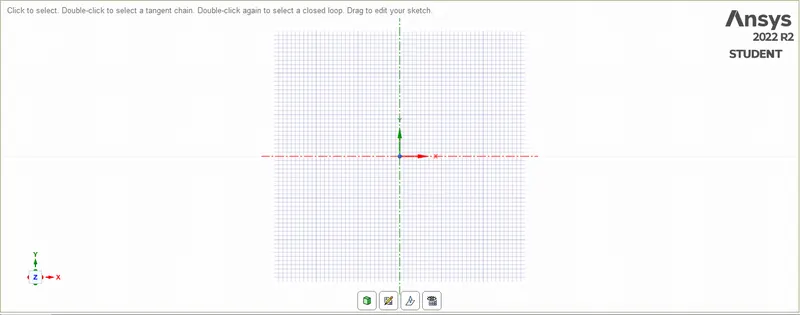
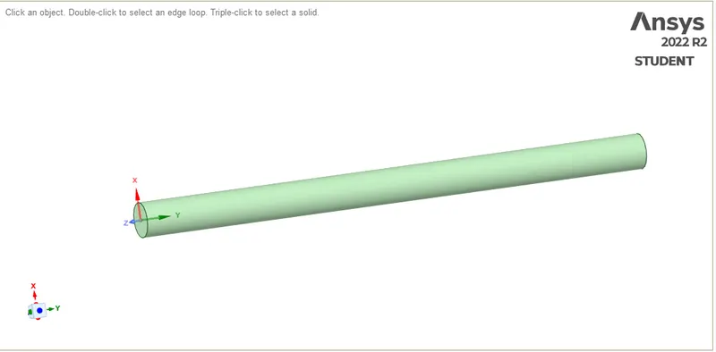
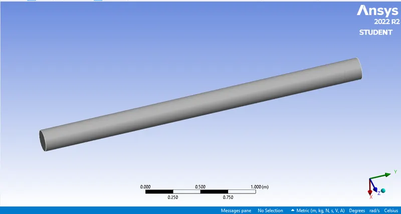
- Create the geometry as shown below using circle tool and create circle by using pull option and rename the surfaces as solid and fluid.
- The created geometry is shown in the below figure.
- Close SpaceClaim and double click on Mesh.
- Meshing window will appear.
- Now select the mesh from the pipe and generate mesh for fine meshing.
- The figures shown below are the final meshed geometry for both the cases.
MESHING:
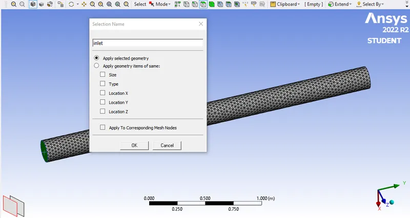
creating the Mesh file, we name the geometry for the further use
- Inlet (inlet where the air come from)
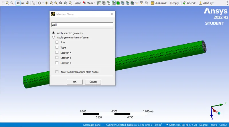
- The walls
- Outlet
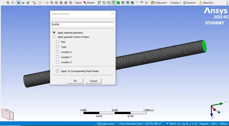
- Fine Meshing
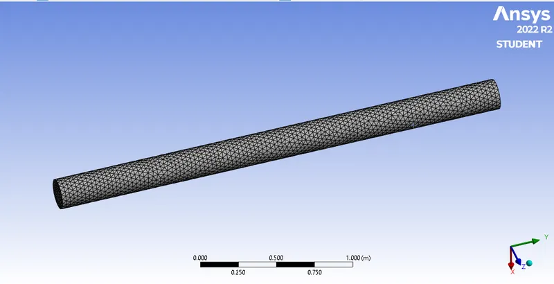
- Close Meshing and double click on Setup, select Double Precision and Fluent window will open. Check all the values and make necessary correction if needed.
- Select the conditions mentioned below.
SETUP:
-
Setting UP Physics:
-
The meshes are set up and the solver is defined below.
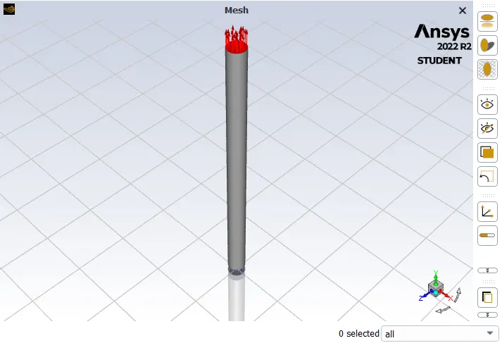
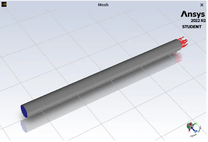
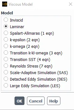
MODEL
- viscous model = laminar
MATERIAL SELECTION
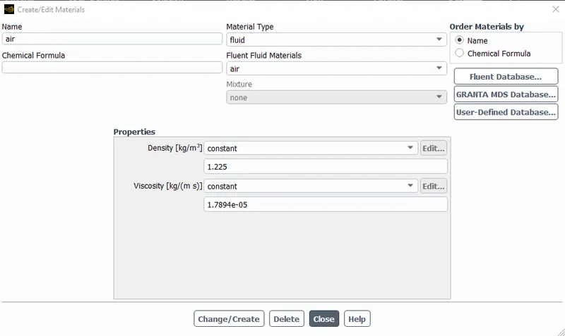
CHANGE AND CREATE MATERIAL
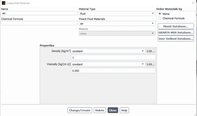
- density = 1 (kg/m3)
- viscosity = 0.002 (kg/ms)
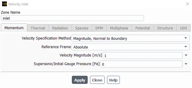
VELOCITY AT INLET
- velocity = 1m/s
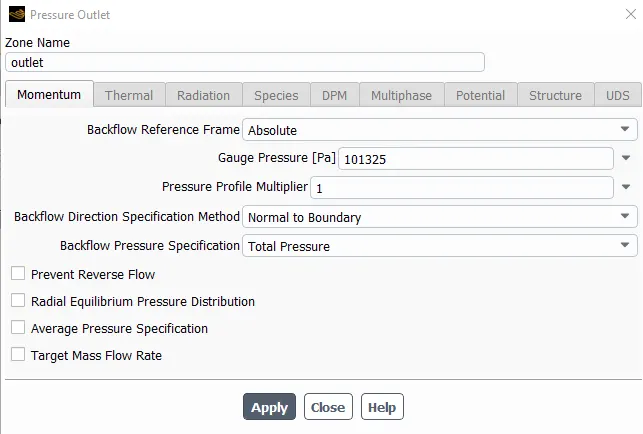
PRESSURE AT OUTLET
- pressure = 101325 pa
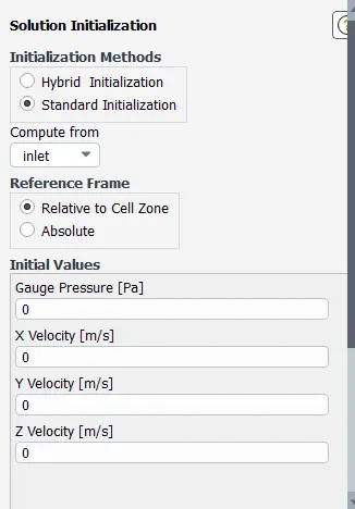
SOLUTION INITIALIZATION
- method = standard initialization
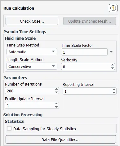
RUN CALUCATION
- number of iteration = 200
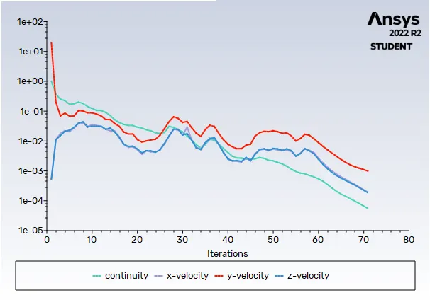
RESULT
Residual
VELOCITY
- VELOCITY CONTOUR
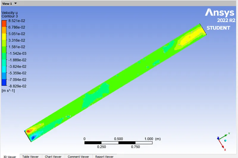
- VELOCITY u CONTOUR
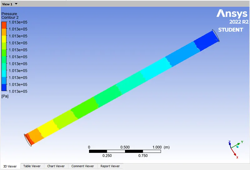
PRESSURE CONTOUR
CONSCLUSION
- Flow through pipe simulation has been done for fluid of particular properties.
- velocity contours are find out laminar flow through pipe is assumed.