Hood design-Week 2
A car hood also referred to as a bonnet in some other countries is the hinged cover that rests over the engine of a front-engine vehicle. Its purpose is to provide access to the engine for repair and maintenance. Car hoods are typically constructed from steel and sometimes from aluminum.
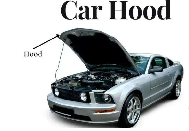
In UK terminology, a hood refers to a fabric covering over the passenger compartment of the car (known as the “roof” or “top” in the US). For many motor vehicles built in the 1930s and 1940s, the resemblance to an actual hood is clear when it is opened and viewed from the front; in modern vehicles, it still serves the same purpose, but no longer resembles head covering.
On front-engined cars, the hood may be hinged at either the front or the rear edge, or in earlier models (e.g. the Ford Model T) it may be split into two sections, one on each side, each hinged along the centerline. A further variant combines the bonnet and wheel arches into one section and allows the entire front bodywork to tilt forwards around a pivot near the front of the vehicle.
Hoods are usually made from the same material as the rest of the body. This can be steel, aluminum, fiberglass, or carbon fiber. However, some aftermarket companies produce fiberglass or carbon fiber steel hood replacements to make the vehicle lighter.
The hood release system is common on most vehicles and typically consists of an inner hood latch/lock handle, a hood release cable, and a hood lock assembly. The hood lock handle is usually located under the steering wheel, next to the driver’s seat, or in the door frame.
For racing cars or vehicles with aftermarket hoods (that do not use the factory latch system) the hood can be held down by hood pins. Some aftermarket hoods that have a latch system still have hood pins to keep the hood buttoned down if the latch fails.
CAR HOOD DESIGN:
To design the car hood and understand the mechanism behind the design of hood, then development& its safety features as per the design consideration.
The following task is performed:
- Design Outer Panel with the Hem
- Develop the Inner Panel
- Develop all the Necessary Reinforcements
- Mirror and position the Hinge & Striker
- Provide Mastic Data
- Provide the required Emboss definition
- Develop a detailed Report for the Mastic position and Embosses you have placed.
according to the master sketch given
the outer pannel of thickness 0.75mm
the inner pannel of thickness 0.75mm
the renforcement thickness 1.5mm
According to the master sketch given and the components are outer panel, striker, hinge assembly assembling all the components to create the hood assembly.
- Creating a new file as Assembly (assembly H) as WCS coordinate system and importing the data given the outer panel, hinge assembly, striker as constrains.
- Inner panel: component which does not exist must be created as a modal and create a datum coordinate system in inner panel.
- Now linking the date of inner panel under the outer panel by using command (WAVE GEOMATERY LINKER).
- For the easy of designing the outer panel divided into two parts and trim one part by (TRIM SHEET) command. Select the body of outer panel, select the boundary in coordinate system and select the region, the wanted section must be keep and remaining is discarded.
- The inner panel has three flanges situated in different hights from outer panel 1.7mm,4mm,25mm. and in different widths. For creating each flange, we use (OFFSET SURFACE, OFFSET IN FACE) commands
- Flange1: taking the half trimmed outer panel (true surface) by using offset surface offsetting the body to 1.7mm down word direction and hiding true surface, and now by offset in face command taking the edge as boundary offsetting the edge inward direction up to 20mm, by trim sheet command selecting the 20mm offset boundary trim the sheet and keep, discard everything.
- Flange2: taking the half trimmed outer panel(true surface) by using offset surface offsetting the body to 4mm down word direction and hiding true surface , and now by offset in face command taking the edge as boundary offsetting the edge inward direction up to 22mm,again by offset in face command taking the edge as boundary offsetting the edge inward direction up to 35mm by trim sheet command selecting the 22mm and 35mm offset boundary’s trim the sheet and keep, discard everything.
- Flange3: taking the half trimmed outer panel (true surface) by using offset surface offsetting the body to 25mm down word direction and hiding true surface , and now by offset in face command taking the edge as boundary offsetting the edge inward direction up to 50mm, by trim sheet command selecting the 50mm offset boundary trim the sheet and keep, discard every thing
- The three flanges created and now connecting them with THROUGH CURVES command, and after connecting for fully connect with out gaps apply SWE operation by SWE command.
- For smoothing of the sharp and corner edged of the flanges apply EDGE BLEND operations .
- Creating a datum plane on the flange 3 for creating the emboses, those emboses will stop the force on passenger when it hit. Drawing a sketch on datum plain accordingly that enible the force traveling inside to cabin. And also sketching masting points on the emboses this maisting points provide support to inner panel and outer panel.
- The sketch on datum plane must be projected on the inner panel by ( project )and by using embossing command embed 8mm in upward directing, for all the embosed surfaces apply the edge blend.
- On ever emboss surface offset the edge inward directing 10mm and sketch maisting poinst on edges and trim the sheet and its look like hallo emboss and masting points , repeat the operation for every emboss. Apply edge blende for every emboss.
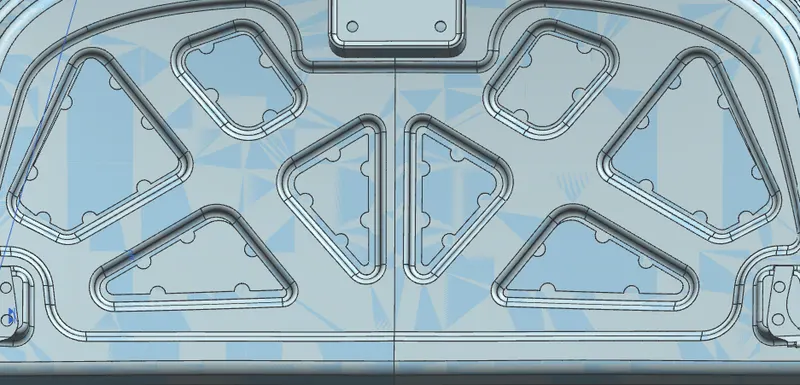
- EMBOSS:When a force impacts the hood from the front, it travels in an upward direction. The component is designed to divert the force away from the passengers into the hinges, as shown in the image belowThe embosses in the inner panel are made according to the diversion of the load path. The emboss depth is kept at a maximum of 5mm to be on the safer side so that the part is manufacturable.
MASTIC SEALANT: The Mastic sealant or the Mastic point is an elastic compound that behaves like a rubber. The mastic points are defined on the hood inner panel where the hood can easily deform. They help the hood outer panel to come back to its original shape after it gets deformed. The mastic has an influence area of 80mm.
- Create a new datum plain for sketching emboss for mounting hinge component. It must be according to hinge measurement, the sketch is projected on inner panel and creating embose and making the edges smooth by edge blend operation.
- Mirror operation: before applying mirror geometry operation the sheet must be extended why because without extending and after mirror operation there will be gaps between two sheets. To avoid this, we must extend the sheet and trimmed to the coordinate axis and extend to 5mm.
- After mirror apply swe operation ..if there are gaps between sheet the operation show the gapes.
- HINGE: by mirror geometry operation mirror the hinge to the other side and apply parlel constrain to hinges lie in same axis and apply touch constraint to attach to the emboss created for hinge.
- Make a 3D point on both hinges middle axis and join with line it will the axis of hood rotation, from the centre point on line make trajectory circle which touches the striker emboss, after that make a tangent on the trajectory.
- Striker: create a datum plane with WCS system in yz axis and make line in middle of striker hook.
- Striker placement: the tangent drawn on inner panel and line on the striker must be linked and move the striker with move command near to the striker placement on inner pannal.
- Creating emboss to striker with the command LAW extension. than the striker placed on embose.
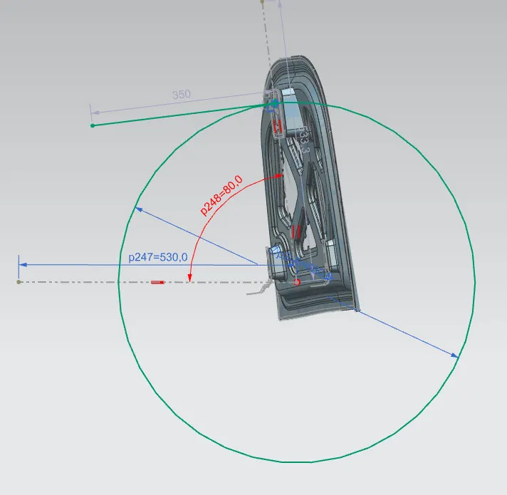
- Outer panel:
- For the easy of designing the outer panel divided into two parts and trim one part by (TRIM SHEET) command. Select the body of outer panel , select the boundary in coordinate system and select the region, the wanted section must be keep and remaining is discarded.
- to avoid the sharp edges offset the sheet edge to 0.1mm and edge radius 5 and trim the sheet.
- Hemming process:Hemming is the process of joining both the outer and inner panel together. The hemming process roles and wraps the hood outer panel around the inner panel and holds it tightly together. The following are the dimensions followed for hemming.
- offset the sheet by offset surface command to 2.65mm and trim the sheet and keep. Joining the offset surface and outer panel by face blend command.
- 0.75*3=2.65
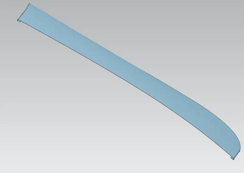
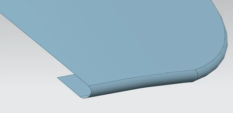
- By curve on surface command select the corner edges of the hemming sheet and trim the sheet. Now apply the mirrorgeometry to apply the mirror surface.
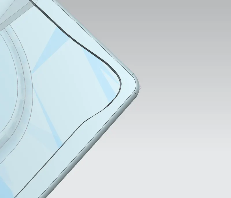
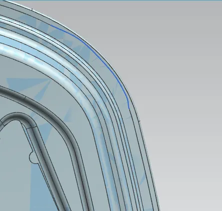
- By thicken command thicken the outer panel(downward) and inner panel(upward) by 0.75mm.
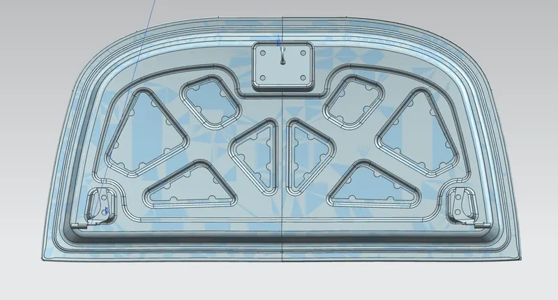
CONCLUSION:
All the parts of the hood are designed based on the required condtions& given values and assembled togather to complete the hood design.