Hood design-Week 2
Aim
- A detailed report about the Hood Design which includes a detailed explanation about hood and its components, Latch Trajectory, Mastic Data, Emboss Definitions, Manufacturing process like Deep-Drawing and Hemming, and all the parameters followed in the design.
Hood, Points to be undertaken for design and Parts/Components of a Hood
Hood
The hood or bonnet is the hinged cover over the engine of motor vehicles. Hoods can open to allow access to the engine compartment (or trunk on rear-engine and some mid-engine vehicles) for maintenance and repair.
Conventional car bonnets today are mostly made of steel or aluminum. Such car bonnets weigh about 10 kg’s. This is considered too high and the potential for improvement by weight reduction is expected. The greatest change for weight reduction is material changes and redesign of the inner panel of the bonnet. The most important criteria to be considered is to reduce pedestrian head injury.
A typical hood assembly consist of hood outer panel, inner panel, latch and striker, hinge, hood stay.
Design Consideration
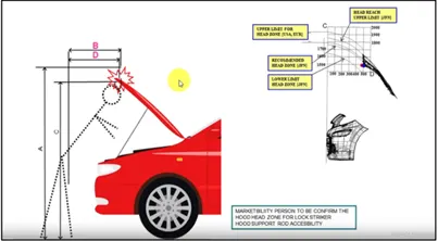
1.The first important criterion for designing the hood is the opening angle of the hood
While designing the hood this parameter should be taken into consideration because when we open the hood to get access to the engine compartment to perform any operation while the hood is in open condition the minimum height of the hood should be such that it does not collide or hit to head of the person who is operating. So, the height of hood in open conditions should be more than the average height of humans in that region thereby no human gets hurt. For example, the average height of a human being in India is 5.8 feet whereas in European countries the average height of a human being is 6 feet. Hence the opening angle of the hood greatly depends on the height of the human which can be controlled by the support rod or gas stay.
2.Hood Stay
This is the support system for the hood as when we open hood we need it to rest to keep it in open position & this can be done by placing it over something or by providing support to it. While designing this one should keep in mind that the support system should be self-sustainable to take the load of the hood even if any external force is being applied on it due to wind or any other reason & it should facilitate easy opening and closing of hood.
This can be done by using two ways
- Support Rod
- Gas stay
2.1 Support Rod
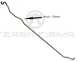
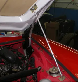
It is a rod that accommodates itself easily inside the engine compartment and support the hood when we open it by attaching the rod in the hook provided inside the hood. Initial bends are being provided to the support rod to provide stiffness.
Support rods length is decided based on the opening angle of the hood. In the support rod maximum bend of 35mm is given in order to strengthen the support rod to bear all the load of the hood. There is the human effort needed.
2.2 Gas Stay
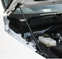
This type of apparatus is used in most heavy vehicles where the weight of the hood is more and it is difficult for a human being to open it conveniently. So, basically, a gas stay system uses gas-filled telescopic cylinders which only require an initial force to set it in motion.
3. Pedestrian safety:
While designing the hood, it is vital to consider the safety of pedestrians as when your car hits the pedestrian during a crash, it is very important to study the areas over the hood where different body parts of pedestrians are going to hit. we should also take into account the average height of adults and children while designing our hood. So, whenever a new car is being launched, all these safety parameters are checked by taking a crash test and studying the data obtained from it to make changes accordingly to follow pedestrian safety.
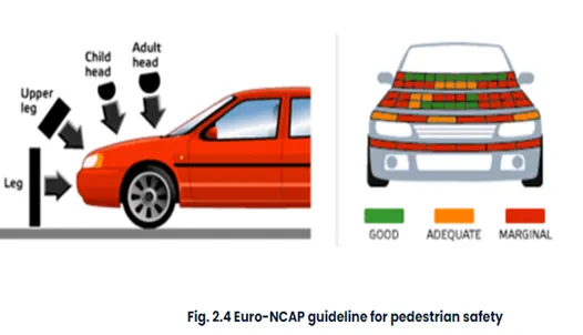
The EURO NCAP has developed a series of crash tests and rating systems for assessing pedestrian, driver, and passenger injuries during impact with of the vehicle.
The below image illustrates a pedestrian is in standing perpendicular to the road and a crash test performed with a head-on collision.
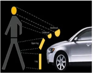
Wrap-around distance: It is the distance from the road to the point where the head of the pedestrian collides with the hood.
In the below images, we can see the wrap-around distance for adults and children.
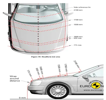
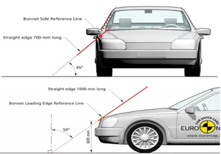
Side reference line: A line is drawn at 45degreedegree from the ground such that it touches the end of the hood. This type of hood is called the inlaid hood. If the end of the point of the side reference line is at A-pillar, then it is called the wrap-around hood.
The position of the side reference line is important because if the side reference line is on the hood resulting in a bigger hood the wrap-around distance will be less and hence the impact zone will be more. But if the side reference line falls on the fender which makes the size of the fender bigger resulting in a lesser hood size which in turn results in high wrap around distance and lowering the impact zone.
4 Under Bonnet clearance
The designed hood is offset to 90mm towards the engine compartment to check the interference of the hood with the hard points in the engine compartment.
This 90mm offset is considered the deformation caused due to the impact and package components that penetrate the deformation zone are checked with different colors as shown in the below figure.
HIC criteria
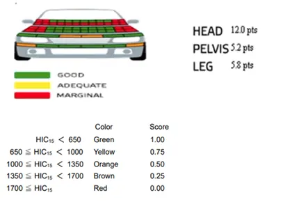
The responsibility of the design engineer is to reduce the red points and increase the green points to pass the safety criteria. This is done after the creation of emboss to reduce the deformation during a collision. Then cut-outs are made such that the penetration points are reduced. When the material is removed the hood gets softer in that region which results in lesser force impact force during the collision. This is done to increase the rating in the crash safety test.
It is to make sure that there is no reinforcement given at the wrap-around distance in order to reduce damage to head injuries to pedestrians in case of head-on collisions.
5 Mastic Data:
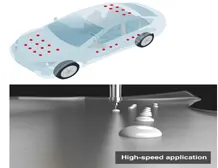
We know that the hood comprises two main parts: a hood inner panel and a hood outer panel. The hood inner panel is enclosed below the outer panel and thereby provides rigidity to the hood. When these parts are assembled to form a hood a small gap remains between these two parts as they are both metal parts this may lead to noise and vibrations when the vehicle is in running condition which is undesirable to avoid this mastic sealant is filled between this small gap.
Mastic sealant is a paste-like material that is applied on a surface and is hardened by heating.
The size of mastic seals is 10 mm in diameter and as per the design consideration there should be minimum 5 mm gap is provided between hood inner panel and hood outer panel to seal the two panel together
6 Force Distribution
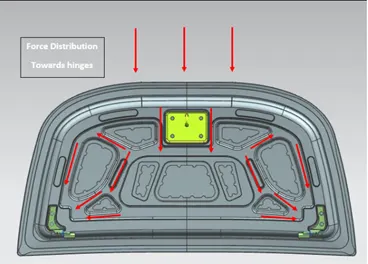
A designer should always consider the safety parameters as a top priority, In the case of hood design, one should design the hood in such a manner that if the vehicle gets a frontal crash then all the forces must be distributed towards the hinge of the hood, as it is important to reduce the impact of the crash by diverting the force towards the hinges and thus safeguard the passengers in the vehicle to achieve that emboss and the cut out are like that given in Y and V ways/section so when the impact comes the force goes into the support or the embosses and the particular area is deformed and the impact of force reduces and it always goes outward
7.Reinforcements
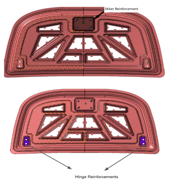
Whenever there is an addition of material to the component there is a loss of strength locally. In this case, the additional material is the striker and hinge where additional reinforcements had to be attached due to loss of strength locally in the attachment areas.
As per the standards the thickness given to the hinge reinforcement is between 1-5 mm and for latch and striker is 1.0 mm and usually it depends upon the loss of strength as the material is removed.
Components
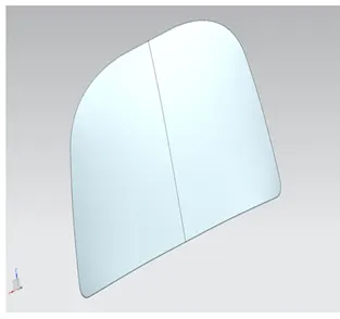
1.Hood outer panel
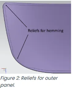
Outer panels are the aesthetic elements of a car. It is the styling team who provides the skin for the outer panel. The shape, position and size of the hood should satisfy the safety norms. So while designing the hood we should give more importance to pedestrian safety. The outer panel is attached to the inner panel by hemming. So, it is necessary to provide required hemming flange and reliefs for the hemming operation. We also provide mastic sealants between outer panel and inner panel to reduce vibration.
2.Hood inner panel
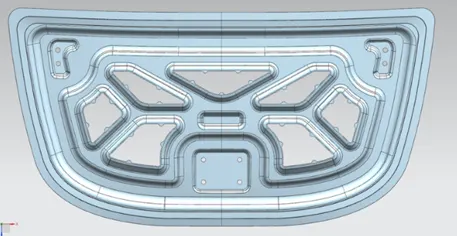
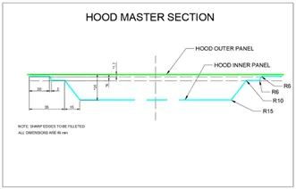
Inner panel is the part that gives strength and rigidity to the outer panel. The master section represents the initial emboss shape and size. Then we provide the emboss for the latch and hinge elements after fixing the location.
3) Hinges
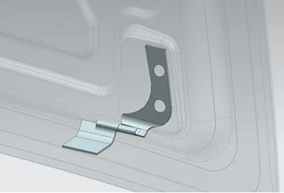
Hinges allow the hood to rotate around a fixed axis for opening and closing movement. One part of the hinge is fixed with the engine compartment, while other part is connected to hood.
4) Latch and Striker
Latch and striker mechanism is provided to lock the hood, in order to prevent accidental opening of the hood during driving. The latch is present on the engine compartment while the striker is attached to inner part of hood.
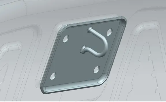
5) Support Rod
It is a device that supports the hood in open position. It is also called as hood balancer rod and it is supported/ rest on Grommet
There are two types of support rod first one is straight support rod and second is gas stay, usually as per the frequent usage we use gas stay in the back side door and the straight support rod is used in the front hood and as per design consideration it is placed opposite side of battery compartment so to make it easy for battery change.
Usually we see two types of support rod one which is straight and other is having same bending the reason behind providing the bending is when load is applied on the bending rod there will be more force distribution (More X and y component to dissipate the load) and less chances of failure of rod and minimum distance with the axis and the bending should be 35mm as per the Indian standard.
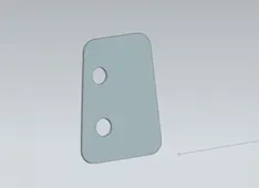
6.Reinforcement
Reinforcements are provided according to the design requirements. Mainly it is provided at the hinge and latch regions to improve the strength locally. Usually thickness of reinforcements will be higher than that of the inner panels and the value varies according to cost and requirement.
7.Latch Trajectory
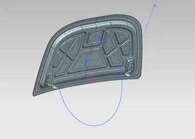
It is the path along which the hood rotates during opening and closing movement. The striker on the hood follows a particular path while opening or closing the hood, which is along circumference of a circle with center at the hinge axis. This path is nothing but latch trajectory. It is a very important aspect in hood design, in order to decide hinge, latch and striker installation points.
In design aspect first, we can fix either the latch or the hinge. If we have fixed the hinge position, then we should plot the Trajectory circle for the latch. For proper mating condition the striker axis through the tip of the striker should be tangential to the latch trajectory and if striker is perpendicular to the trajectory then our hinge position is correct or else we have to adjust the position of hinge.
8.Emboss definitions
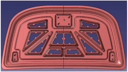
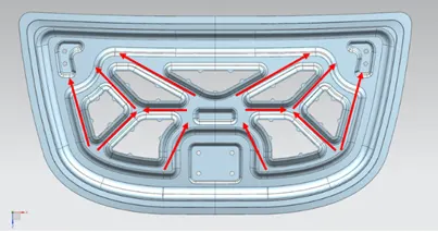
Throughout the inner panel we provide different embosses. We can increase the stiffness of the inner panel through these embosses. The shape and size of the embosses also determines the direction of the force distribution resulted from frontal collision. The force should be always distributed away from the passengers. Here in the figure the embosses are designed in such a way that the force is directed to either sides of the car.
9.Mastic Data
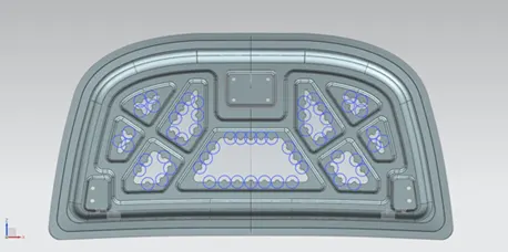
Hood commonly possess large surface area and hemming can only be provided through its boundary. We cannot use other joining techniques like welding, riveting because they leave marks on the outer panel which spoil its aesthetic appearance. So, mastic sealants are used to stick the inner surfaces of outer panel and inner panel. Mastic sealants are elastic compound that behave like rubber. It is applied between the inner and outer panels at specified spots. Each spot of mastic sealants has its effect around a circular region of 80mm diameter. Thus, the mastic points are arranged in such a way that it covers the areas away from the hemming which are more vulnerable to vibrate.
10.Deep Drawing
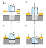
Deep drawing is one of the most widely used processes in sheet metal forming. Apart from its use in many other sectors, it is applied in the automotive industry for the manufacturing of car body parts. The deep drawing process is a forming process which occurs under a combination of tensile and compressive conditions.
Sheet metal blank is radially drawn into a forming die by the mechanical action of a punch. It is thus a shape transformation process with material retention. The process is considered "deep" drawing when the depth of the drawn part exceeds its diameter. This is achieved by redrawing the part through a series of dies. The flange region (sheet metal in the die shoulder area) experiences a radial drawing stress and a tangential compressive stress due to the material retention property. These compressive stresses (hoop stresses) result in flange wrinkles. Wrinkles can be prevented by using a blank holder, the function of which is to facilitate controlled material flow into the die radius.
11.Hemming
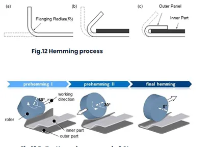
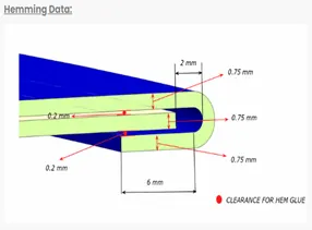
Hemming is a forming operation in which the edges of the sheet are folded or folded over another part in order to achieve a tight fit. Normally hemming operations are used to connect parts together, to improve the appearance of a part and to reinforce part edges.
In car part production, hemming is used in assembly as a secondary operation after deep drawing, trimming and flanging operations to join two sheet metal parts (outer and inner) together. Typical parts for this type of assembly are hoods, doors, trunk lids and fenders.
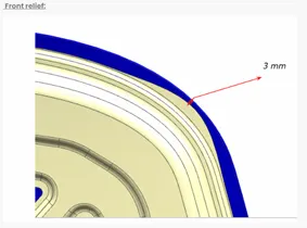
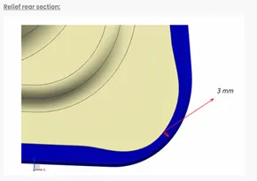
The accuracy of the hemming operation is very important since it affects the appearance of the surface and surface quality. Material deformations, which occur during the hemming process, can lead to dimensional variations and other defects in parts. Typical hemming defects are splits or wrinkles in the flange, material overlaps in the corner areas or material roll-in. This is why it is important to provide required reliefs at the corners.
Types of hems
- Open Hem
- Rolled Hem
- Tear Drop Hem
- Closed Hem
There are two types of hemming operations
- Conventional die hemming
In conventional die hemming, the flange is folded over the entire length with a hemming tool.
- Roll hemming
It is the roll hemming process that is used for automotive sheet metals. Roll hemming is carried out incrementally with a hemming roller. An industrial robot guides the hemming roller and forms the flange. Roll hemming operation can also be divided into several pre-hemming and final hemming process steps. Roll hemming is very flexible to use and tool costs are significantly lower as compared to those of conventional die hemming. However, the cycle times are much higher since the hemming is realized using a hemming roller which follows a defined path.
12. Piercing
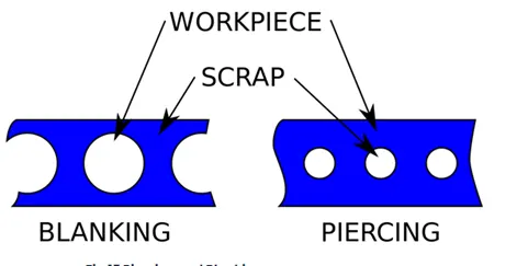
It is a shearing process in which raw sheet metal is pierced with a machining tool, resulting in the creation in a particular shape hole in the sheet. The major difference between blanking and piercing is that in blanking the cut out is the workpiece and the outer part is scrap, while in piercing, the cut-out is scrap and the outer sheet is the workpiece.
Manufacturing processes can quickly and cleanly create solid metal parts and forms. The process uses specialized dies that press sheets of metal into precisely the right form. Auto manufacturers benefit from using metal stamping for parts like fenders and hub caps because the dies can be used again to create consistently sized and shaped parts that meet tight specifications and tolerances.
Design Methodology
- First the inner panel is designed from the given master section using the various commands and features. We create the embossing using the offset surface from the original master section. Similarly, we create the cuts on the emboss by sketching and using trim surface option.
- Then the outer panel is designed from the same master section. Here we are supposed to provide the hemming to outer panel. The parameters of hemming are taken as per given values.
- Now, on the inner panel, the embossing for hinge and striker are produced by considering their respective dimensions and assembly positions. First the emboss for hinge is created and then by fixing the hinge into its position, we draw an axis passing through both side hinge axes to form a common axis. And then we position the striker such that it will move along circumference of a circle whose center is at midpoint of the common axis. Thus, position of striker is decided and we can create emboss for the same.
- Using the hinge emboss we created, we can create our hinge reinforcements by creating new parts in the assembly itself.
Points to keep in Mind while hood design
- The minimum distance between two blend should be 5mm.
- The minimum distance between 2 fillet should be 5mm at least.
- Mastic seals radius should be 10mm in diameter and 5mm in radius.
- Blend radius for emboss should be 3 plus thickness.
- Basic criteria for hinge emboss and striker emboss is it should be flat and it is checked by local radius analyzer (infinity means flatter surface).