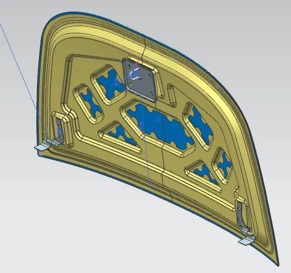
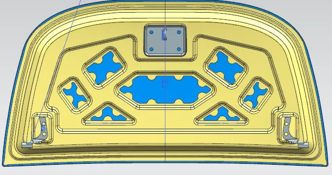
Hood design-Week 2
Hood Design
- Create a new assembly and insert a hood outer skin part save the file in the single folder.
Hood Inner Panel
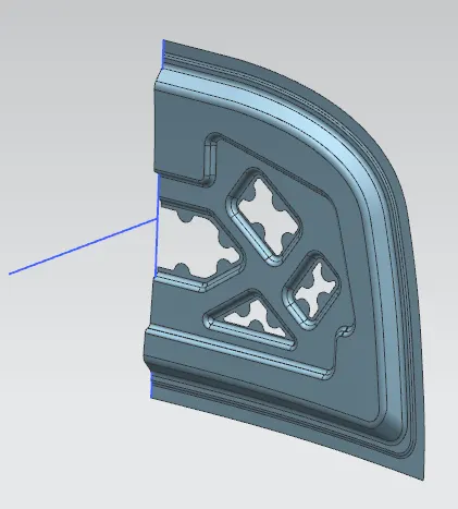
- Create new part as Hood inner panel in the assembly file and Using wave geometry linker to Extract the surface from the outer panel.
- By using 3D Sketch create a tooling axis for using direction creating emboss and other directions.
Flanges
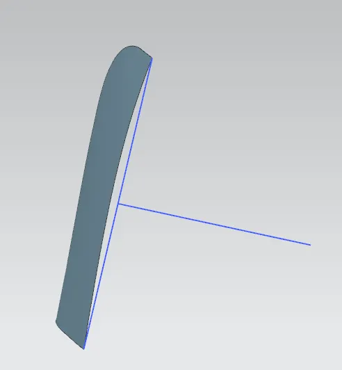
- Offset the surface and using offset curve surface tool make a curve by offsetting the boundary by given master section data.
- Using Trim sheet remove the surface and creating flanges by joining through curve tool.
- Fillets are given to the all the sharpen edges and join all the flanges.
Emboss and Mastic Data
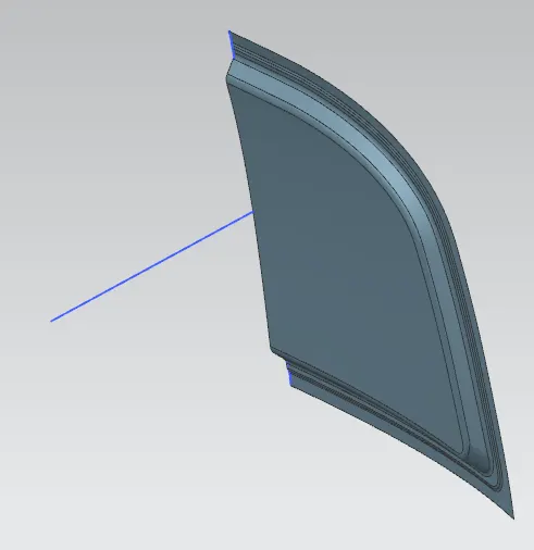
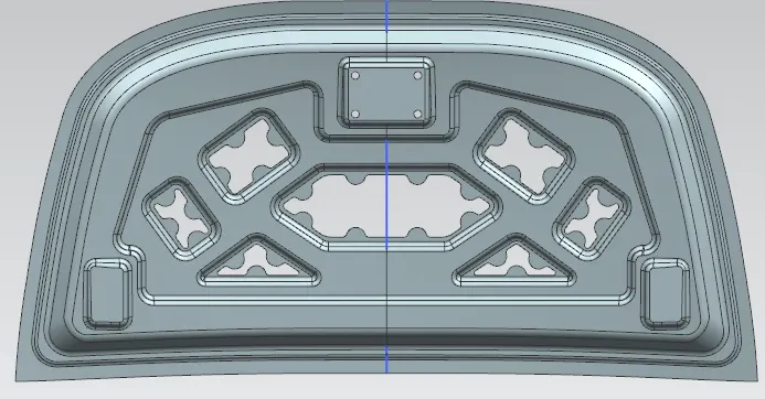
- Separate sketches were created to emboss the hood which is used strengthen the hood for develop in crash test.
- Create emboss offset sketch were created in sheet and make a cutout as mastic for purpose of pedastrian safety.
Hinge & Striker Mount
- Create a sketch with clearance on bottom and make an emboss.
- Trajectory sketch was created for hinge axis and mirror the geometry.
- Extract the behind the surface of striker and using law extension tool create surface on tooling axis direction.
- Trim and Extend tool is used make a striker mount.
- Thicken the part for final assembly.
Assembly
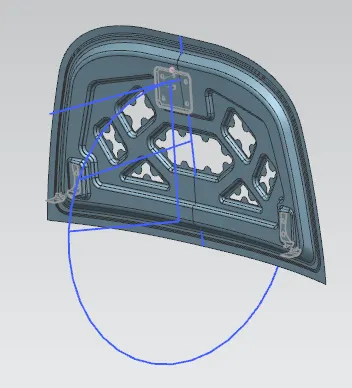
- Insert hinge assembly and striker in the assembly part and using assembly constraint to assemble the part.
Hood Outer panel
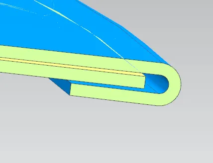
Heming
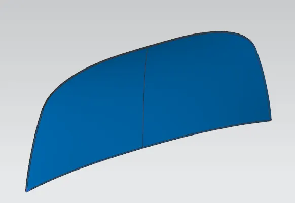
- Offset the surface from the given datum master section
- Using trim sheet tool to trim the offset surface. and create perpendicular surface by law extension tool.
- joint the three faces by face blend tool to be a single part and mirror the half part.
- Thicken the component.
Final Assembly