BIW Enclosure Deisgn Front Hood of a CAR with design Consideration for Manufacturing and EURO NCAP saftey Requirements
BIW Enclosure Deisgn Front Hood of a CAR with design Consideration for Manufacturing and EURO NCAP saftey Requirements
INTRODUCTION
Automotive industry is the fastest growing industry today. In the competitive business, the automotive companies haveto take care the market demand. The customer choice is change from day to day, hence the vehicle must be upgradeas per requirement. Now a day the sport utility vehicle is in demand. Every vehicle manufacturing company like Mahindra, Tata, Honda, Hyundai, VW, etc are upgrading the vehicles as per customer demand. The theme of vehicle is mostly change as per market requirement. Theme is mainly depending upon the hood assembly, bumper assembly,fender, side panel and front light assembly of vehicle. Vehicle manufacturer changed theme of car by changing the closer style. Customers demanding the luxuries look of car with high efficiency and low prize. Hence the research work is in the progress of making light weight vehicle with better stiffness. The major challenge for automotive industry is to make light weight components and improving the other efficiency parameter. This work is focus on the design and development of new hood assembly for better in stiffness of hood assembly. which satisfy manufacturing parameters .
1. BIW
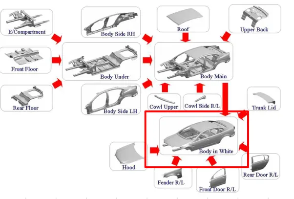
BIW Stands for Body in white . In Automotive Industry BIW is defined as the structure of car before painting in other words its group of sheet metal welded structure including Hood , Doors,Chasis Sub assemblies etc . BIW makes a Design into reality its an structural development of complete CAR by joining set of sheet metals to make complete structure using Welding,brassing,reviting etc.
2.HOOD (BONNET)
Hood is defined as part of the vehicle body which covers the top of the engine in front engine vehicles. In mid-engine cars the panel which conceals the engine is called the "engine cover " or access panel .Hinged cover that rests over the engine of a front-engine vehicle. Its purpose is to provide access to the engine for repair and maintenance. A concealed latch is typically used to hold down the hood. On vehicles with an aftermarket hood and on racecars, hood pins may be used to hold down the car hood. Hoods sometimes also contain a hood scoop, wiper jets, power bulge, and/or hood ornament. Car hoods are typically constructed from steel and sometimes from aluminum.

3. OBJECTIVE
The Main objective of this project is to design a car hood BIW structure with considering of all manufacturing parameters with Design satisfication of Fuctional Requirments
as well as EURO NCAP standards .
4. COMPONENTS ASSOCIATED WITH HOOD
The Hood Consists of following parts
- Hood Outer Panel
- Hood Inner Panel
- Latch Stricker
- Hinge Assembly
- Support Rod OR Gas stay
4.1 HOOD OUTER PANEL
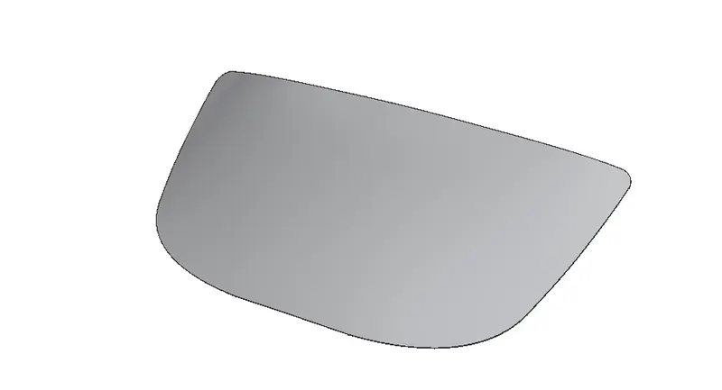
- The hood Outer panel is basically a CLASS A surface which is given by styling team
- Its a Painted Parts which is seen outside of the body
- Its Manufactured my deep drawing method
- The thickness of the Outer panel according to input is 0.75mm
4.2 HOOD INNER PANEL
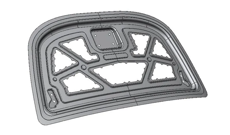
- Hood inner panel is CLASS B surface whuch is laid under class A surface which create a strengthen the strcture of the panel
- Hood Inner panel which satisfies Sectional modulus to create a stifness along hood
- Hood inner panel is plays a moajor role in hood strength and stifness
4.3 LATCH STRICKER
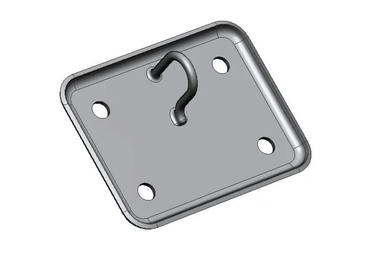
Latch Stricker is a Metal plate welded with hook like structure used to Lock the Hood with engine compartment. type of mechanical fastner that joins two (or more) objects or surfaces while allowing for their regular separation. A latch typically engages another piece of hardware on the other mounting surface. Depending upon the type and design of the latch locking Mechanism will change .
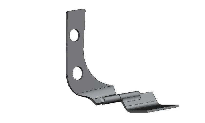
4.4 HINGE ASSEMBLY
Hinges are mechanical bearings used to create a limited and fixed range of rotational movement between two workpieces. Most doors, for instance, are affixed to a frame with two or more hinges. Hinges allow car hood and Engine Compartment for rotation but typically only to a certain degree. Hinges will stop rotating upon reaching this limitation.
4.5 HOOD STAY
- SUPPORT ROD
- GAS STAY
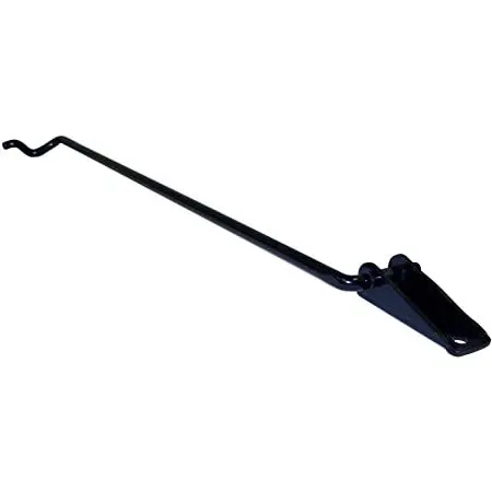
4.5.1 SUPPORT ROD
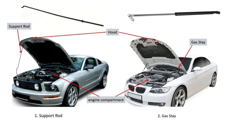
Support rod is cylindrical rod with bends according to axis of Engine front cover which is commonly located to opposite side of Battery setup . It is Coventional type hood stay used in cars act as manual hood holder which supports hood while opening
ADVANTAGE
1. Support rod is simple Mechanism
2. Low cost
DISADVANTAGE
1.Support rod has to be fixed manually
2.Since its an Metalic rod its unable to open the hood in bare hands to inspect Engine after immediately after Stop the vehicle .
4.5.2 GAS STAY
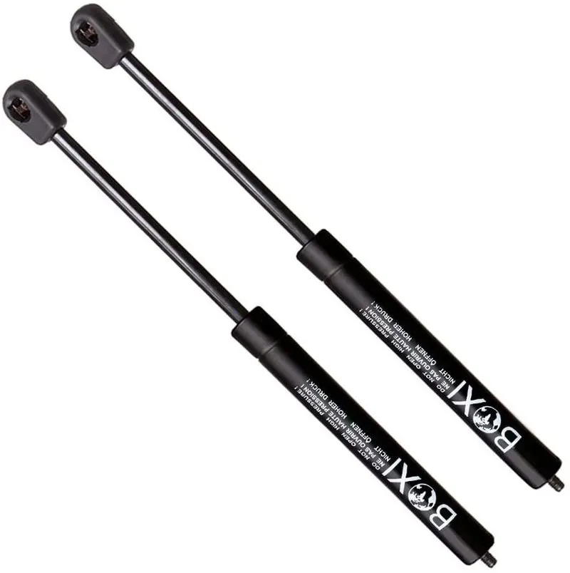
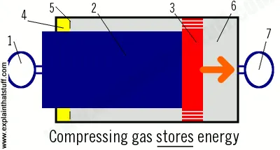
A gas stay is a type of Spring that, unlike a typical mechanical spring that relies on elastic deformation uses compressed contained within an enclosed cylinder sealed by a sliding piston to pneumatically store Potential and withstand external Force applied parallel to the direction of the piston shaft. It holds the hood automatically with out any support .
ADVANTAGE
1.Its Fully auotomated one
2.Rust free
DISADVANTAGE
1.Its much costlier compare with tradtional support rod
5. DESIGN PARAMETERS TO DESIGN A AUTOMOTIVE HOODS
The Design parameters to develop a automotive hood has certain limits and creterias to achieve the manufacturing qualities.
PARAMETERS TO CONSIDER
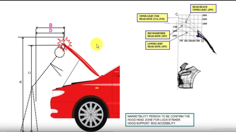
5.1 HEAD CLEARANCE ZONE
Head clearance zone is a main parameter to consider while designing of hood .
Head clearance is used for while opening a hood its chance the hood strike on users head for this reason its consider based on Geometric location of car manufactures the size variation done by gas stays and hinge assembly creates changes in head clearnce .
5.2 Head impact criteria for pedestrian safety
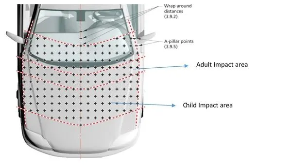
The EURO NCAP Safety Assessment Program includes a test protocol for pedestrian protection. The protocol covers lower leg, upper leg, and head impact tests shown as A, B, C, and D in along with a schematic explanation of the wrap around distance (WAD).
The head impact test assessment results mainly depend on the hood structure, whereas the leg impact tests results are highly influenced by components adjacent to the hood. Because the focus of this communications is on the hood design concept, the results presented in this study are limited to the head impact test results.
The new hood concept is evaluated according to the EURO NACAP 2015B test protocol. In that test protocol, semi-spherical headforms are used (3.5 kg for the child headform and 4.5 kg for the adult headform). The headforms are launched such that the angle at impact is 50° ± 2° (child headform) and 65° ± 2° (adult headform), at a velocity of 11.1 ± 0.2 m/s (which corresponds to an accident with a vehicle speed of 40 km/h). The measurements from the accelerometers mounted in the headforms are processed to calculate the corresponding HIC values, which are used in the evaluation/assessment according to the test protocol.
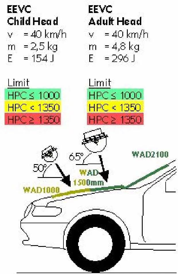
which corresponds to the maximum average acceleration value over time duration t2−t1">t2−t1t2−t1, during the impact event. For the results presented in this article, an HIC-time interval of 15 ms was used. For further details regarding the test procedure, we refer to Euro NCAP 2015.
5.3 NVH ( NOISE VIBRATION HARSHNESS )
Now a days the NVH is important factors in modern cars which is a main consideration to reduce noise and vibration of a car .
NVH is widely used in the automotive industry for the reduction, design, and quality assurance of interior and exterior vehicle Noise or vibration. The process usually takes place during the vehicle development of passenger cars.
NVH can be tonal such as engine noise, or broadband, such as road noise or wind noise. Basically, it is everything that drivers or passengers can either hear and feel from a car while driving, such as wind noise, road noise, bumps from the suspension, or vibrations from the engine.
NVH is to be reduced by using certain materials including stiffner pads .Mastic sealant which splited in between panels etc .
6. DESIGN ASPECTS
6.1 MASTER SECTION CREATION
An Master section creation is based on market requirements and what are the type of vehicle for the hood is done. Based on this data the master section is created by geeting a skin data fro m styling team to create a section data .
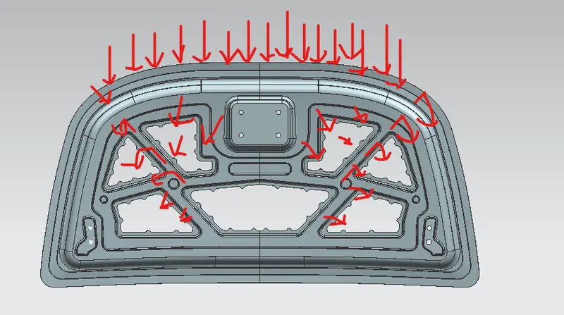
6.2 GEOMETRIC SECTION MODULUS CREATION FOR STIFFNESS
The geometric which is created based on master section to increase the resisitance for force that did'nt reach passenger . For this reason geometric embosses created for neglecting the force outwards from the hood when the force given to the front side . The force diverted to outwards for that the emboss which satisfy'es under the geometry of y type structure .
6.3 CREATION OF EMBOSS LANDING AREA
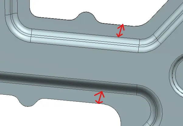
The main design aspects of embossing is to be giving a landing area of minium 5mm of gap in between every embossing takes place in hood design
6.4 POSTIONING LATCH STRICKER AND HINGE USING LATCH TRAJECTORY DATA
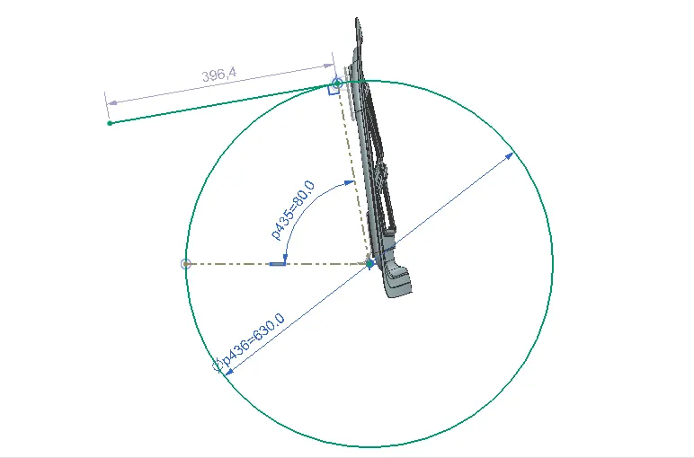
The postioning of latch stricker and hinge assembly by certain methods which is latch trjectory motion the latch stricker has to be mount according to
the axis of the hinge assembly located which the trajectry circle guie the opening and closing of hood along with certain angle .
The trajectory axos line is perpendicular to the centre of hinge assembly axis based on this axis the latch stricker is to be positioned
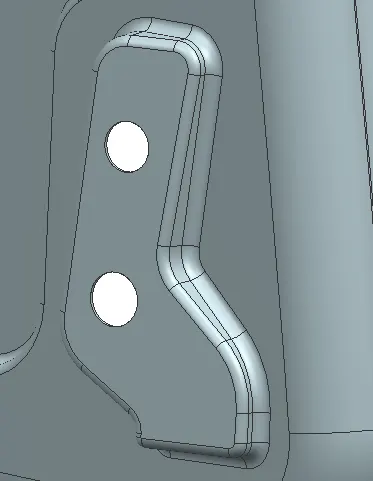
6.5 LATCH STRICKER AND HINGE REINFORCEMENT CREATION
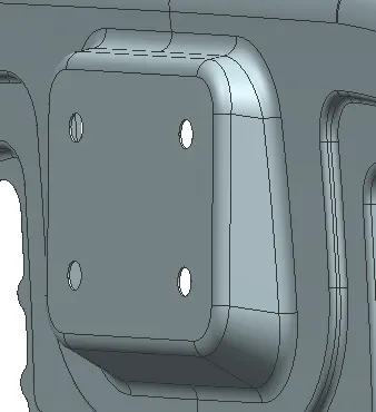
The latch stricker and hinge assembly which is addtionaly added parts to the hood inner panel .Need to add additional reinforcement for increase the strength of the particular area to with stand addtional force and help to stop reduce shear stress added at the area of welded and bolted joints near tp the latch stricker
and Hinge assembly .
The mounting and welded surface is always to be flat for that reaseon the creation of reinforcement is to flat according to the Engine compartment .
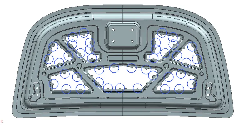
6.6 MASTIC SEALANT
The Mastic sealant can be used to either join one surface to another, or protect the area to which it is applied . Mastic sealant is a chemical cpomponent its apply in between outer panel and inner panel . Automotive hood is a styling surface so its not possible to create a spot welding so mastic sealent is act as
support for fixing two panels .Mastic selant has effective of 80mm diameter to cover all over the surface .
6.7 HEMMING
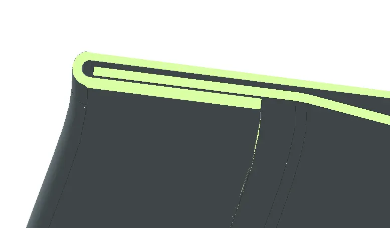
Hemming is a process of joinning of two sheet metals . In this process the outer panel and inner panel hemmed together.
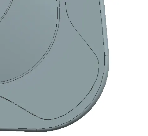
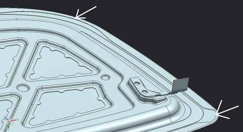
6.7.1 HEMMING RELIEF
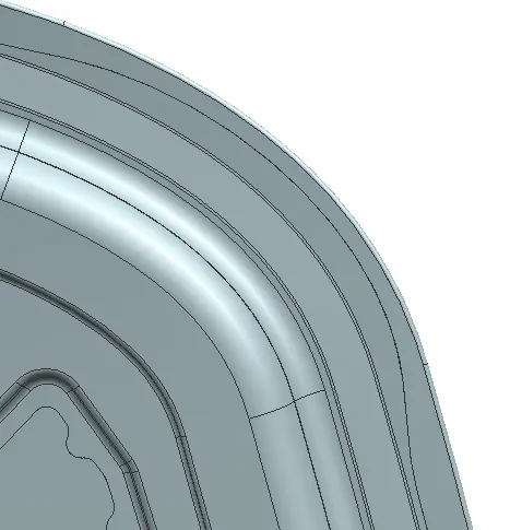
Hemming relief is defined as use to reduce the stress concentration at the corner of edges. It also neglect the overlapping of materials .
7.MANUFACTURING METHOD
7.1 MATERIALS USED FOR HOOD DESIGN
The material selection is based on the properties and strength of material.
|
Material properties |
Steel AISI 1045 |
Al 6061 |
|
Density(Kg/m3) |
7850 |
2700 |
|
Poisson’s ratio |
0.3 |
0.33 |
|
Young’s modulus (MPa) |
21000 |
70000 |
|
Yield strength (MPa) |
505 |
275 |
|
UTS (MPa) |
585 |
310 |
7.2 CUTTING
Cutting. Perhaps the most commonly used metal fabrication including cutting , where sheets of metal are split into halves, thirds or smaller sections. In a lot of applications, the metal being cut is freshly made, and has yet to be shaped into anything in particular. In other applications, pre-shaped metals like bars and measured panels are submitted for cutting. Cuts are performed on a range of machinery, from lasers and plasma torches to more elaborate, high-tech pieces of machinery.
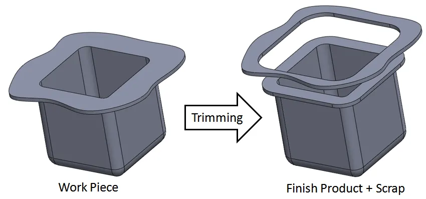
7.3 TRIM
Trimming is the removal of excess metal from a stamped part to allow the part to reach the finished stage or to prepare it for subsequent operations.
also subtract the unwanted edges
7.4 STAMPING
Stamping is a cold-forming method that transforms flat metal blanks into various shapes. The process uses a tool and die, which, when impacted, change the form of the metal through the use of shear pressure.
Stamping is a broader term within sheet metal manufacturing. It encompasses punching, bending, as well as embossing. It also incorporates flanging, which entails swiping the sheet of metal in such a way as to form flanges.
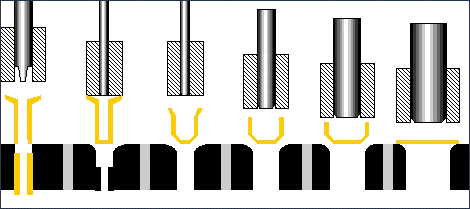
7.5 DEEP DRAWING
The deep draw forming process begins with metal blanks . Typically, single blanks are used in order to facilitate the creation of parts or products with deeper shapes. Sometimes, these metal blanks will be placed on a reel to enable the metal to form efficiently. At each step in the deep drawing process, the metal blank is shaped through pressure applied by a metal die.
Though deep drawing is similar to metal stamping, the terms are not interchangeable. Stamping does not leave a single machine until the metal has completely formed. In general, deep drawing is used to fabricate parts and products that are deeper than metal stamping can accommodate.
7.6 HEMMING
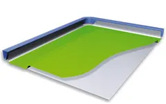
Hemming is a forming operation in which the edges of the sheet are folded or folded over another part in order to achieve a tight fit. Normally hemming operations are used to connect parts together, to improve the appearance of a part and to reinforce part edges.
In car part production, hemming is used in assembly as a secondary operation after deep drawing, trimming and flanging operations to join two sheet metal parts (outer and inner) together. Typical parts for this type of assembly are hoods, doors, trunk lids and fenders.
The accuracy of the hemming operation is very important since it affects the appearance of the surface and surface quality. Material deformations, which occur during the hemming process, can lead to dimensional variations and other defects in parts. Typical hemming defects are splits or wrinkles in the flange, material overlaps in the corner areas or material roll-in. This is why it is important to use simulation tools in order to, on the one hand, better understand the hemming process and, on the other hand, significantly reduce the number of “trial and error” loops during tryout und production.
There are various types of hemming operations:
- Conventional die hemming
- Roll hemming

7.6.1 Conventional die hemming
Conventional die hemming is suitable for mass production. In die hemming, the flange is folded over the entire length with a hemming tool. Normally the actual hemming is a result of a forming operation in which the flange is formed with a hemming tool after the drawing and trimming operations have been completed. The formed flange is then hemmed in several process steps. These steps include, for example, the pre-hemming and final hemming depending on the respective opening angle of the flange. Production plants for conventional die hemming are very expensive, but the cycle times are very low.
7.6.2 Roll hemming
Roll hemming is carried out incrementally with a hemming roller. An industrial robot guides the hemming roller and forms the flange. Roll hemming operation can also be divided into several pre-hemming and final hemming process steps. Roll hemming is very flexible to use and tool costs are significantly lower as compared to those of conventional die hemming. However, the cycle times are much higher since the hemming is realized using a hemming roller which follows a defined path.
8.TOOLING AXIS
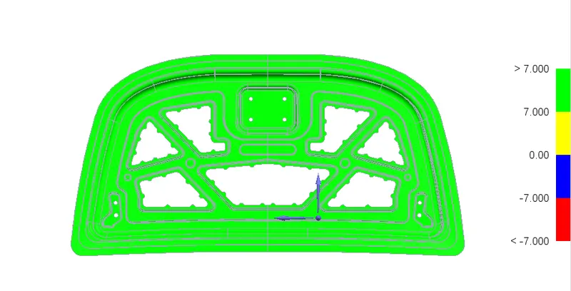
The tooling axis defined as draft analysis which is mean to reducing the tool wear it should be maintain maximum 6 degree of postive draft to maintain
9. VIEWS OF HOOD
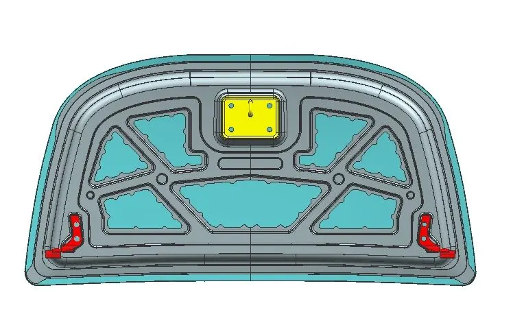
9.1 FRONT VIEW
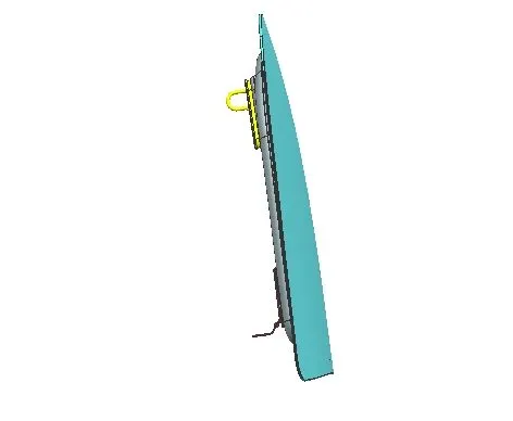
9.2 SIDE VIEW
9.3 TOP VIEW
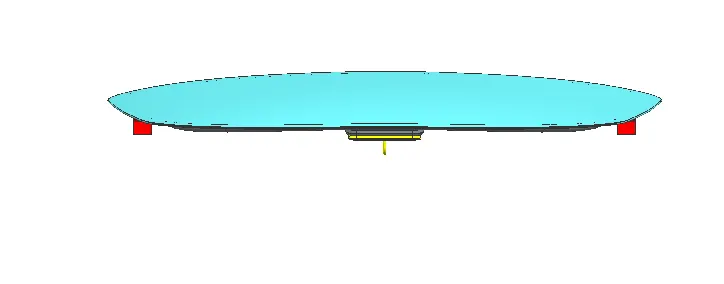
9.4 ISOMETRIC VIEW
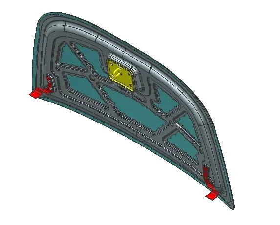
9.5 CROSS SECTION
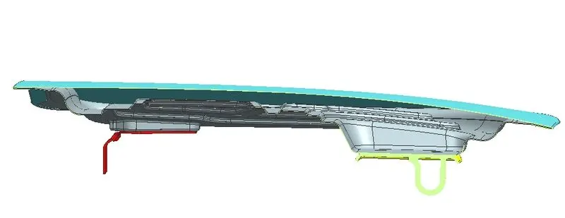
CONCLUSION
This entire project is done by using NX CAD . Which satisfy all engineering aspects of hood including NCAP standards , Manufacturing Process