Hood design-Week 2
AIM
HOOD DESIGN CHALLENGES
- Hood Section
The sub assembly hood consists of a hood, striker, opening system, latch and insome cases pedestrian safety system. The main functions for the hood are to protect the under-hood system and work for pedestrian safety. The system should allow inspection of the engine and service of the under-hood systems, for example filling fluids. Together with the latch system and opening system,the hood should fulfill the demands in ergonomics concerning opening-closing forces and opening geometry. It should be robust enough to not be damaged by normal daily usage of the car.
Hood Complete
The complete hood consists of an inner and an outer plate joined together by hemming around the edges of the hood. Rubber based glue is used in the flange joint as glue between outer and inner hood and on points as well in the inner platepattern as anti-flutter. Today a certain pattern is used in order to fulfill the requirements for pedestrian safety and total stiffness in the hood. Frontreinforcement (=lock striker reinforcement) and hinge reinforcements (steel) are clinched to the inner plate. Spot welding is used in part assembly of front reinforcement.
Hood Geometry
The hood geometry has a huge influence on the pedestrian safety of the hood. The different shapes like bends and roundings makes the hood stiffer and harder in some places, a head impact in these areas can lead to large damage. Then the more flat area of the hood are more soft and more gentle for a pedestrian head impact.The inner hood has a complex design and geometry, this is necessary because it helps to distribute the stresses throughout the hood. It also consists of different holes for manufacturing and assembly.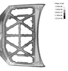
Pedestrian Protection
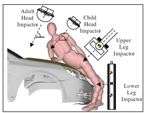
According to accident statistics about 41.000 deaths occur in traffic. 6.100 (15%) of these are pedestrians and another 3.900 (10%) are cyclists.For pedestrians the most frequent injuries occur in the head, upper and lower limbs. 62% of all fatalities are caused by head injuries.
To reduce the death of pedestrian and injuries in the traffic, measures from the automotive industry as well as environmental changes are required
Wrap Around Distance
The WAD is good indicator of where head impacts are likely to occur on the bonnet. By use of the WAD, it can reasonably estimate where on a vehicle a child or adult pedestrian's head may impact
Defining WAD
Mark on the bonnet top, windscreen, A-Pillars or roof (depending on the size and shape of the vehicle being tested) the 1000mm,1250mm,1500mm,1700mm,1800mm and 2100mm wraparound lines. These are the geometric traces described on the top of the bonnet by the end of flexibletapeorwire 1000, 1250,1500,1700,1800 or 2100mm long, when it is held in a vertical plane of the car and traversed across the front of the bonnet and bumper.
DESIGN INEER PANEL Master sketch:
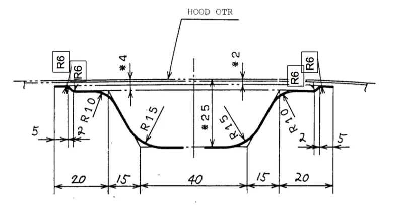
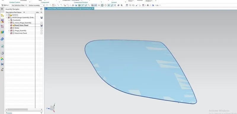
STEP-1 Take skin data into the assembly
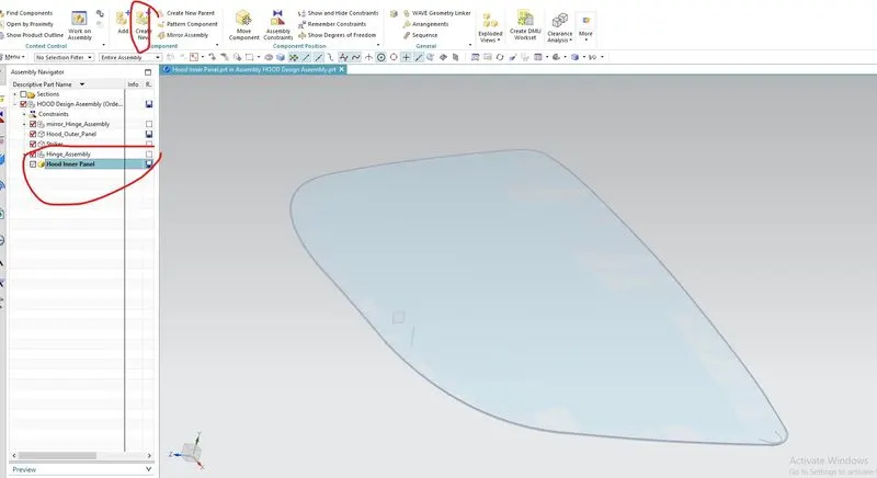
STEP-2 create a new assembly file on same location with name of Hood ineer panel
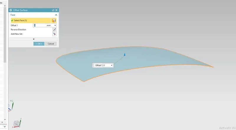
STEP-3 Offset that inner panel 0 mm from outer panel
STEP-4 trim body that body W.R.T mid plane.
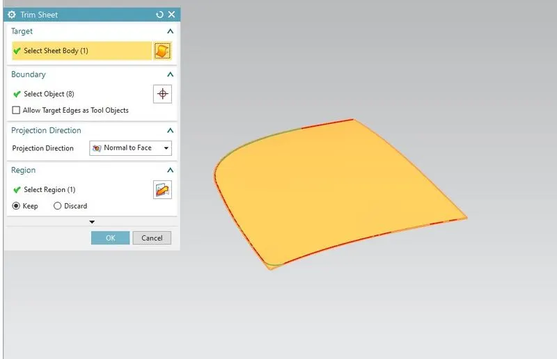
STEP-5 Offset that face 2 m as given in master sketch.
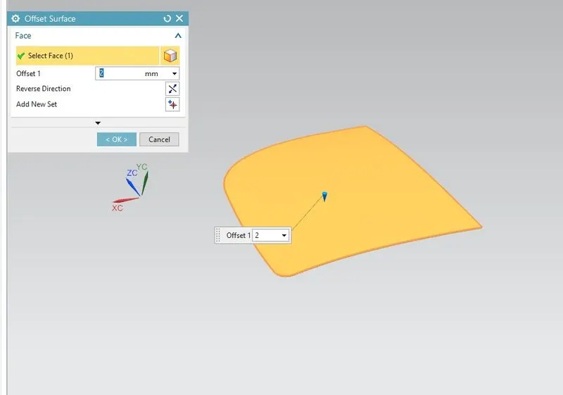
STEP-6 Then offset in face 15 mm from outer Egde
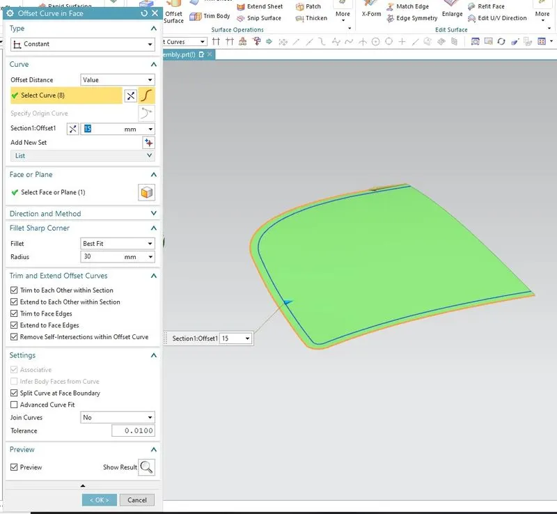
STEP-7 apply trim sheet o/p
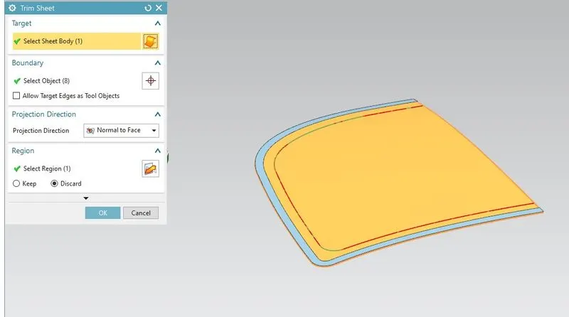
STEP-8 offset that outer face inside 4 mm and apply offest in faces
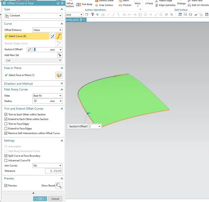
STEP-9 offset that face on trim the sheet as for master sketch
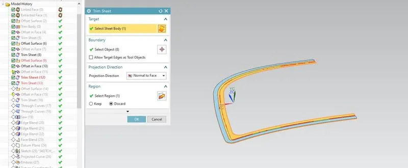
STEP-10 Apply the Though curve
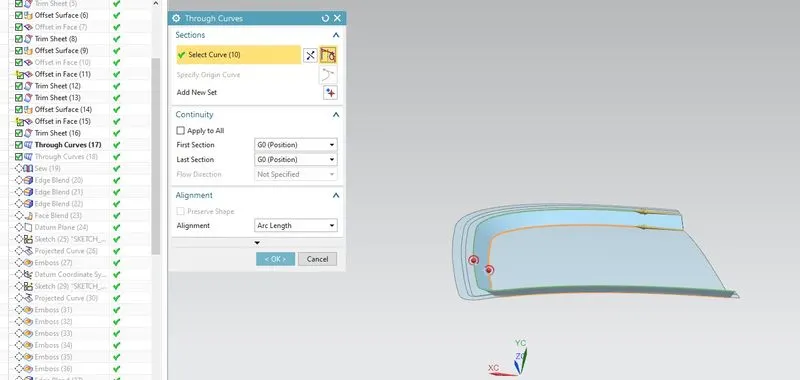
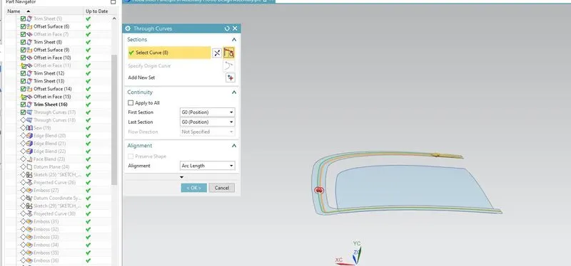
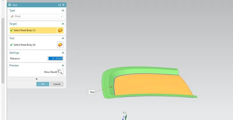
STEP-11 combind the surface by sew
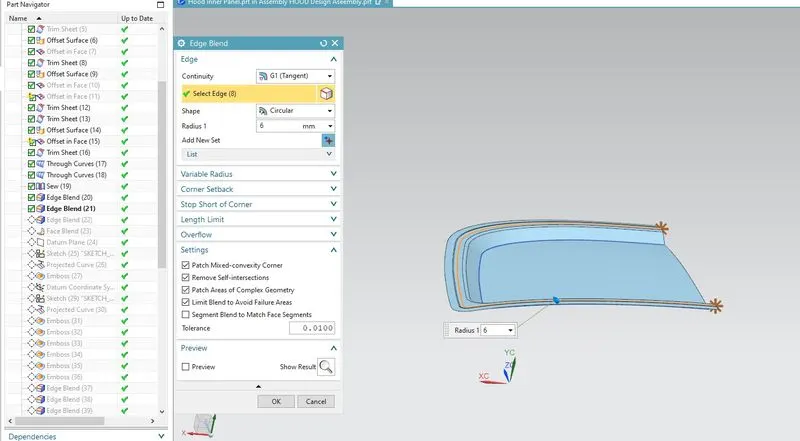
STEP-12Apply the egde blend to the egdes face
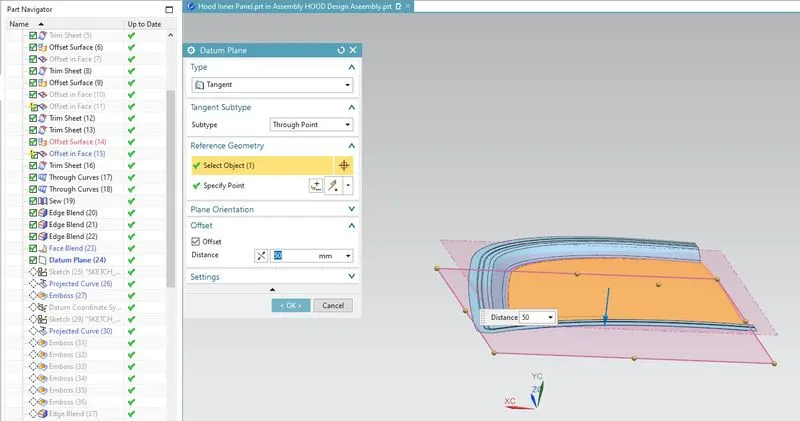
STEP-13 create datum
Emboss
The metal sheet embossing operation is commonly accomplished with a combination of heat and pressure on the sheet metal, depending on what type of embossing is required. Theoretically, with any of these procedures, the metal thickness is changed in its composition.
Metal sheet is drawn through the male and female roller dies, producing a pattern or design on the metal sheet. Depending on the roller dies used, different patterns can be produced on the metal sheet. The pressure and a combination of heat actually "irons" while raising the level of the image higher than the substrate to make it smooth. The term "impressing" refers to an image lowered into the surface of a material, in distinction to an image raised out of the surface of a material.
In most of the pressure embossing operation machines, the upper roll blocks are stationary, while the bottom roll blocks are movable. The pressure with which the bottom roll is raised is referred to as the tonnage capacity.
STEP-14 Create a emboss sketch, projecct and create emboss
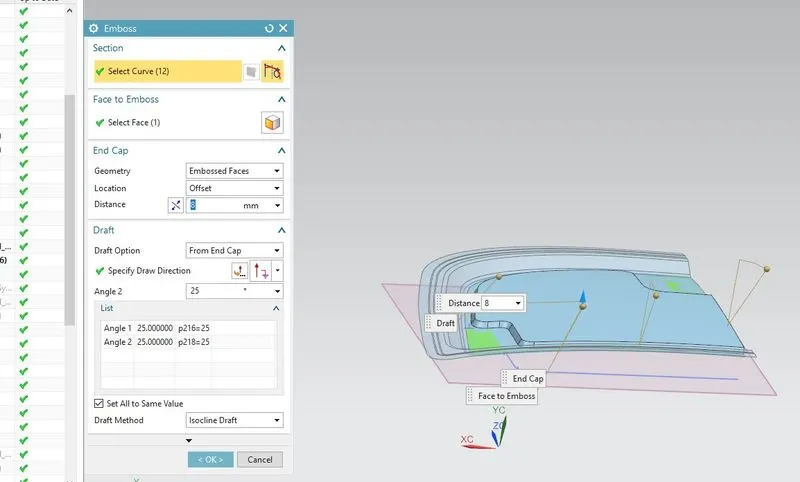
STEP-15create datum plane for 2rd emboss
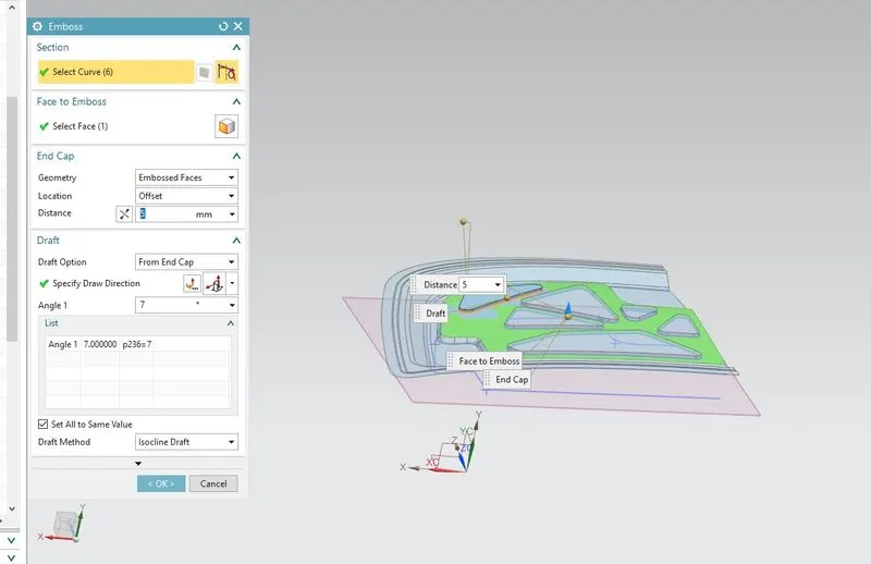
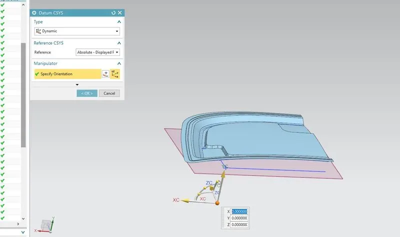
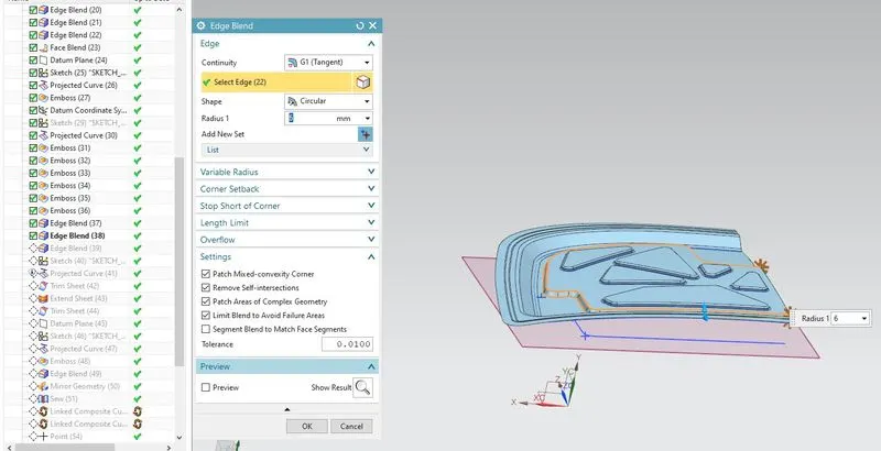
STEP-16 apply edge blend
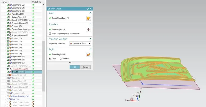
STEP-17 create trim sheet showing figure
Mastic
Mastic is used to join the inner and outer panel with 5mm gap. Emboss is given so that during the crash the energy is
dissipated outside / away from the vehicle occupants and along with the other cut outs to reduce the weight. Along with
reduction in weight it even doesn't cost as it is a cut out
STEP-18 extend the sheet and trim it about mid plane
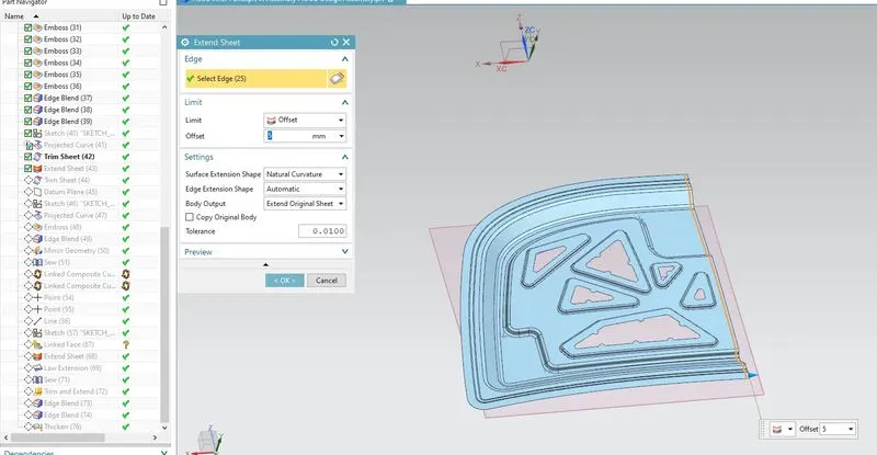
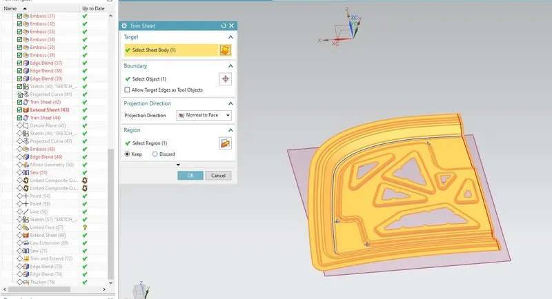
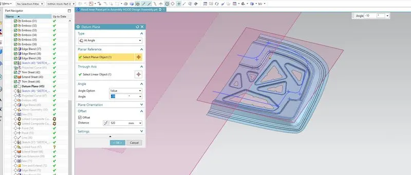
STEP-19 Create datum plane to place hinge on planer face
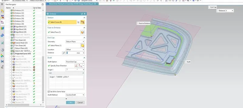
STEP-20 Than create emboss by create that poject sketch
STEP-21 SEW that surfaces
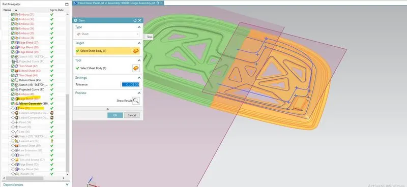
STEP-22 create point on hinge center and join it by line
latch systems
It specifically pertains to those latch systems on hoods, which when the hood is fully opened (assuming the absence of hood stops) extend at any point above a horizontal plane through the uppermost edge of the steering wheel in the straight ahead driving position with the vehicle in a horizontal position
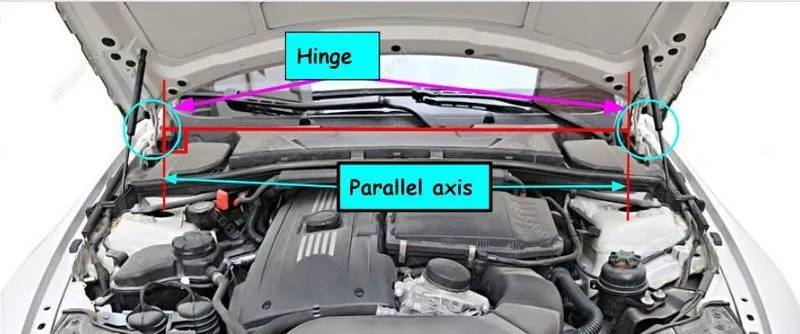
Positioning of Hinge and Striker
Taking centre of axis of hinge as centre of the circle drawn through the striker distance as the radius. It is positioned tangent,
so that perpendicularity is obtained.
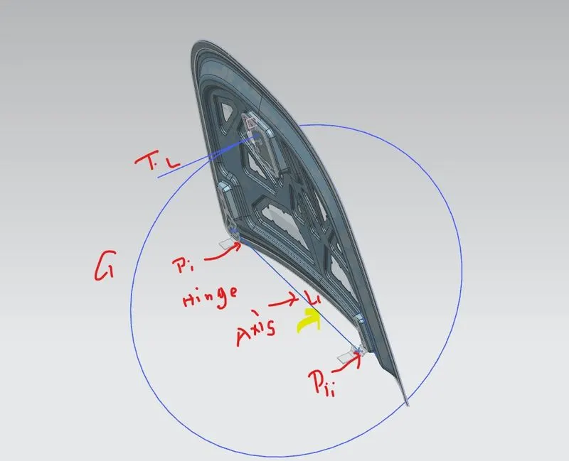
STEP-23 create that circle nad tangent line for assembly of striker
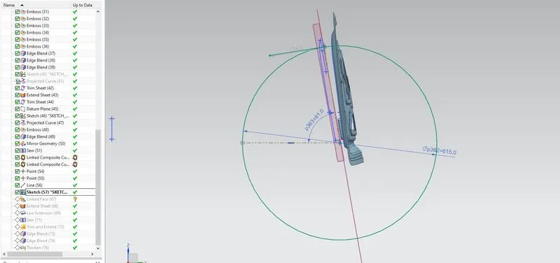
STEP-24 Create a assembly of striker by applying constrain on it
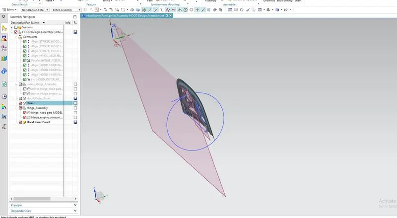
STEP-25 create a emboos planner face for placing striker
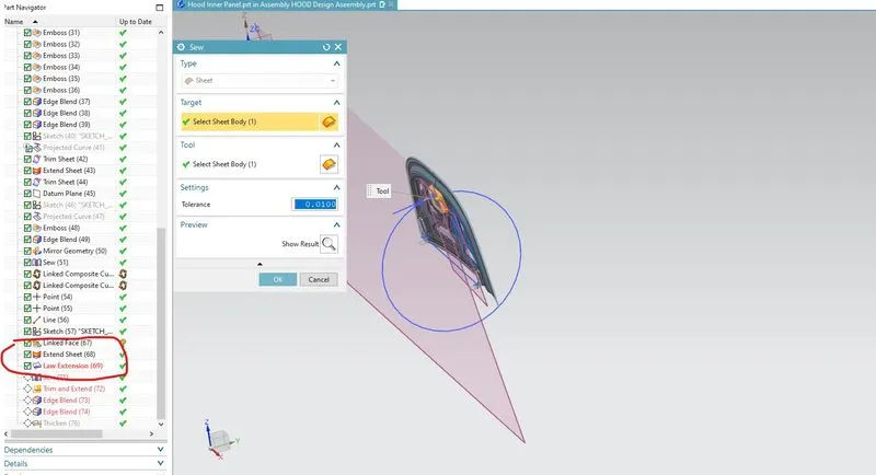
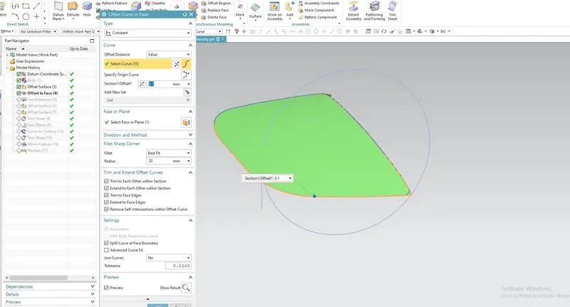
STEP-26 now we create a hemming part of outer panel apply offset at 0 distance and offset curve face
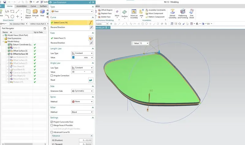
STEP-27 apply law Extension
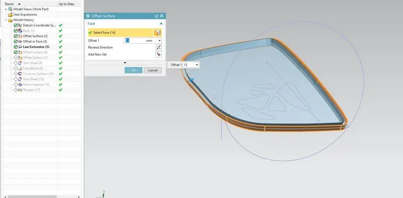
STEP-28 Apply offset surface
STEP-29 Trim sheet to create that hem
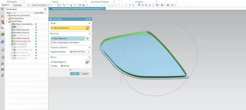
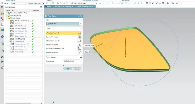
STEP-30 apply three face blend
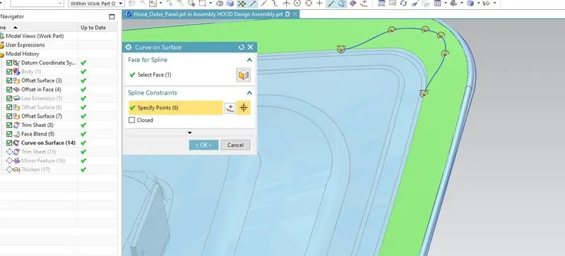
STEP-31 now create curve on surface
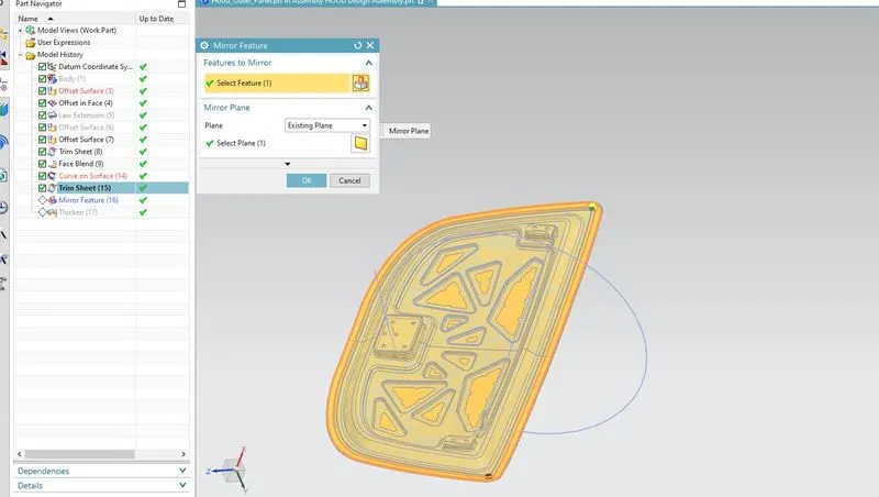
STEP-32 Mirror that feature
view 1
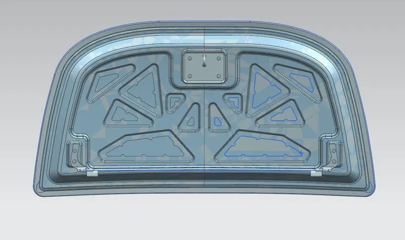
view 2
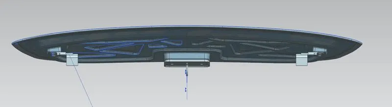
view 3
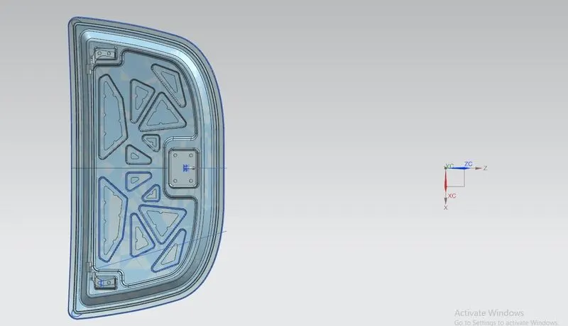
Hemming
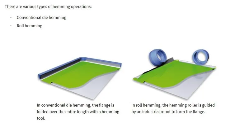
Hemming is a forming operation in which the edges of the sheet are folded or folded over another part in order to achieve a tight fit. Normally hemming operations are used to connect parts together, to improve the appearance of a part and to reinforce part edges.
In car part production, hemming is used in assembly as a secondary operation after deep drawing, trimming and flanging operations to join two sheet metal parts (outer and inner) together. Typical parts for this type of assembly are hoods, doors, trunk lids and fenders.
Deep drawing
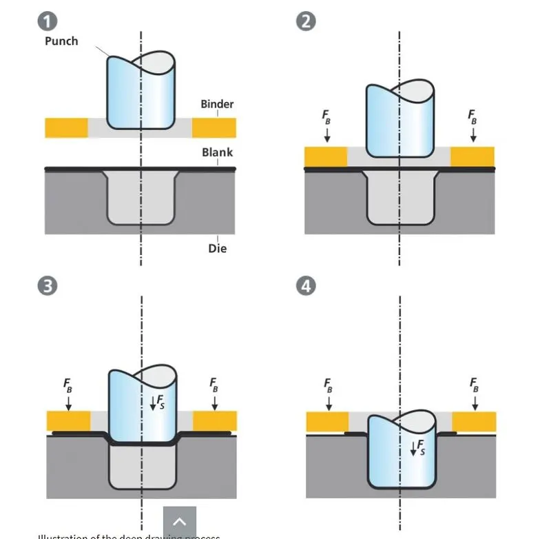
Deep drawing is one of the most widely used processes in sheet metal forming. Apart from its use in many other sectors, it is applied in the automotive industry for the manufacturing of car body parts.
Process definition:
The deep drawing process is a forming process which occurs under a combination of tensile and compressive conditions. A flat sheet metal blank is formed into a hollow body open on one side or a hollow body is formed into a hollow body with a smaller cross-section. [DIN 8584]
Deep drawing processes are divided into three types:
- Deep drawing with tools
- Deep drawing with active means
- Deep drawing with active energy