Hood design-Week 2
OBJECTIVE:
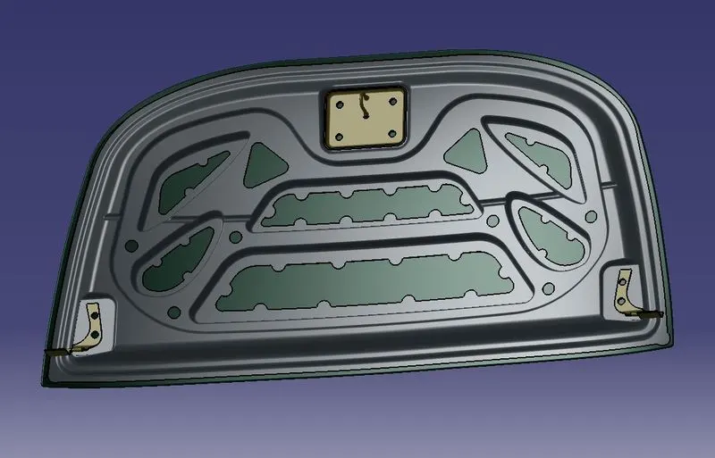
To create the 3D models of the Outer and Inner panels from the given Class-A surface of the HOOD.
THESIS:
The HOOD of an automobile is also refered as the BONNET. The HOOD is used in order to protect the engine compartment for the external atmospheric conditions and also to decrease the drag generated without the Hood.
As a result of increased damand for automobiles, the demand for better Quality, Technology, Safety, Manufacturability etc also increases.
In the case of the exterior body panels of an automobile, the demand for Pedestrian safety along with lighter weight, structutrally rigid components has drastically increased.
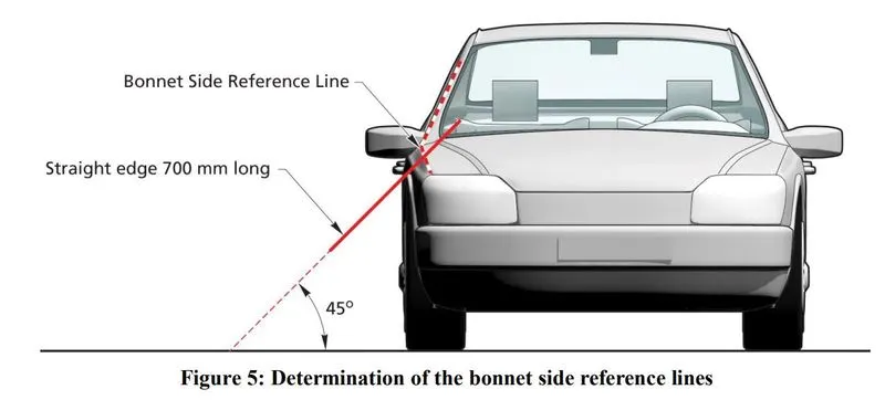
- Bonnet Side Reference Line:
The Bonnet Side Reference Line is defined as the geometric trace of the highest points of contact between a straight edge 700mm long and the side of a bonnet, as defined in Section 3.3.1 and A-Pillar, when the straight edge, held parallel to the lateral vertical plane of the car and inclined inwards by 45 degrees is traversed down the side of the bonnet top and A-Pillar, while remaining in contact with the surface of the body shell, any contact with door mirrors is ignored. See Figure 5. Where multiple or continuous contacts occur the most outboard contact shall form the bonnet side reference line.
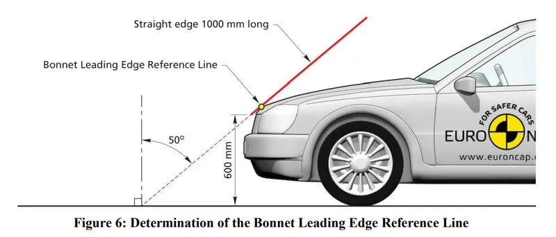
- Bonnet Leading Edge Reference Line:
The Bonnet Leading Edge Reference Line is defined as the geometric trace of the points of contact between a straight edge 1000mm long and the front surface of the bonnet, when the straight edge, held parallel to the vertical longitudinal plane of the car and inclined rearwards by 50 degrees and with the lower end 600mm above the ground, is traversed across and in contact with the bonnet leading edge, see Figure 6. For vehicles having the bonnet top surface inclined at essentially 50 degrees , so that the straight edge makes a continuous contact or multiple contacts rather than a point contact, determine the reference line with the straight edge inclined rearwards at an angle of 40 degrees. For vehicles of such shape that the bottom end of the straight edge makes first contact then that contact is taken to be the bonnet leading edge reference line, at that lateral position. For vehicles of such shape that the top end of the straight edge makes first contact then the geometric trace of 1000mm wrap around distance will be used as the Bonnet Leading Edge reference line at that lateral position. The top edge of the bumper shall also be regarded as the bonnet leading edge, if it is contacted by the straight edge during this procedure.
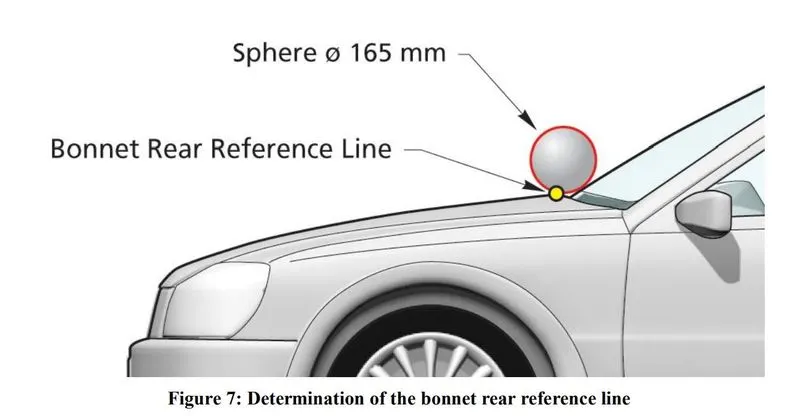
- Bonnet Rear Reference Line:
The Bonnet rear reference line is defined as the geometric trace of the most rearward point of contact between a 165mm sphere and the frontal upper surface, when the sphere is traversed across the frontal upper surface, while maintaining contact with the windscreen.
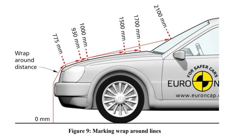
- Marking Wrap Around Distances:
The headform test area is defined as the outer structure that includes the upper surface of all outer structures. It includes, but is not limited to, the bonnet, wings, windscreen scuttle, wiper arms/spindles, windscreen frame, A-pillars and roof. It is bounded by the geometric trace of the 1000mm wrap around line in the front, the Bonnet Side Reference Lines and the 2100mm wrap around distance (WAD).
- Identification of the Head impact Grid Points:
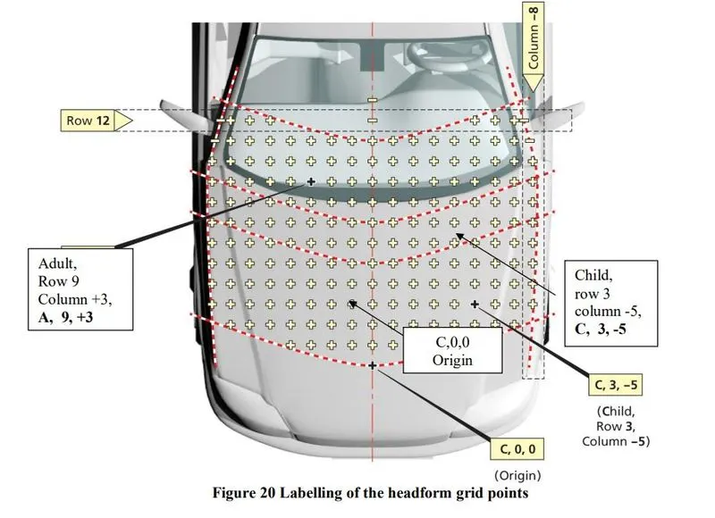
- All child/small adult head impact grid points will contain the prefix ‘C’. All adult headform
points will contain the prefix ‘A’. - The grid point will be identified by means of a row and column system. The origin will be
at the grid point on the vehicle centreline and the 1000mm WAD. This point is C0,0. - The rows at the origin will be row 0, the subsequent rows will be marked in increasing
increments of 1 up to the rearmost row. - The column on the centreline will be column 0, the adjacent column on the right of the
vehicle, as shown below, will be column +1, with the other columns increasing by 1 toward
the SRL, i.e. +2, +3, ….+8. The column on the left of the vehicle will be column -1 with the
other columns decreasing by 1 toward the SRL, i.e. -2, -3, ….-8. - Every point will be identified firstly by the relevant headform impactor (A or C), then by the
row, then by the column. See Figure 20.
DEVELOPMENT OF THE HOOD IN 3D:
Now that we have the basic design criteria for deisgning the HOOD, we can start modelling our HOOD according to the EURO-NCAP standards.
firstly, let us lay down the "Components" of the Hood and then move on to the "Design Procedure" of the component.
- COMPONENTS:
- Outer Panel.
- Inner panel.
- Striker.
- Hinge.
- Reinforcements.
- Stiffener pad.
- DESIGN PROCEDURE:
- create the inner panel layout.
- Create Embosses.
- Create Cut-outs.
- Create Embosses/Debosses for Hinge and striker.
- Create Reinforcements for the Hinge and striker.
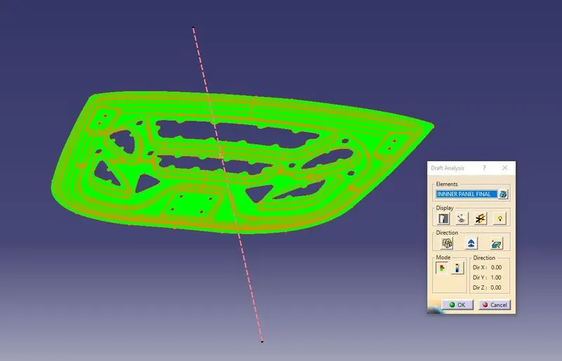
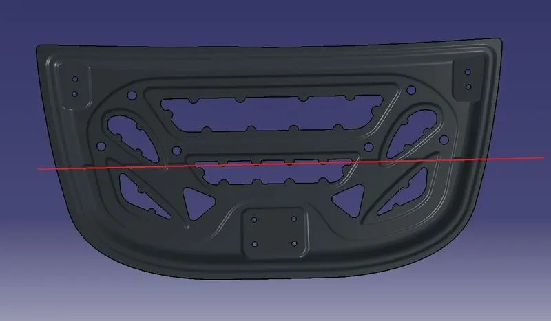
- Perform Draft Analysis on the Inner Panel.
- create Hem for the Outer panel.
- Create Relief Cuts for the Hem on the outer panel.
- Assembly.
1. Creation of inner Panel:
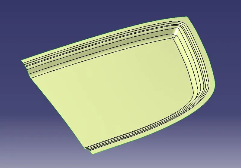
The inner panel can be created by offsetting the Outer Panel Class-A surface according to the Master section and then developing it from there.
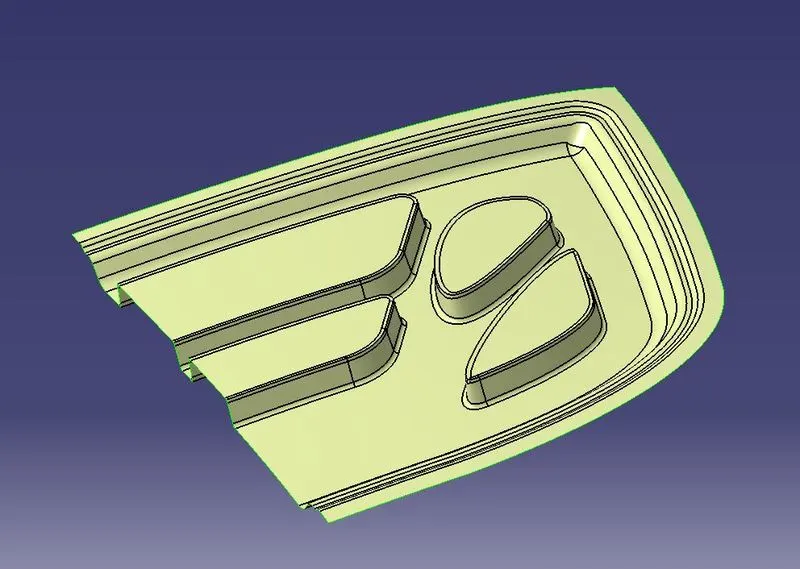
2. Creation of Embosses.
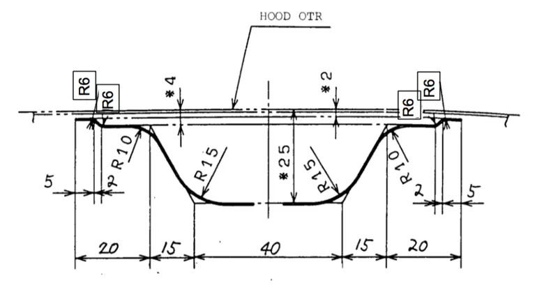
The Embosses are created in order to create cutouts of the Adult and Child Head Impact zones but also to provide structural rigidity to the out panel and to also facilitate the Mastics Points as adhesion points to the Outer Panel. The Embosses also play a role in air circulation around the engine compartment by provide room for heat dissipation.
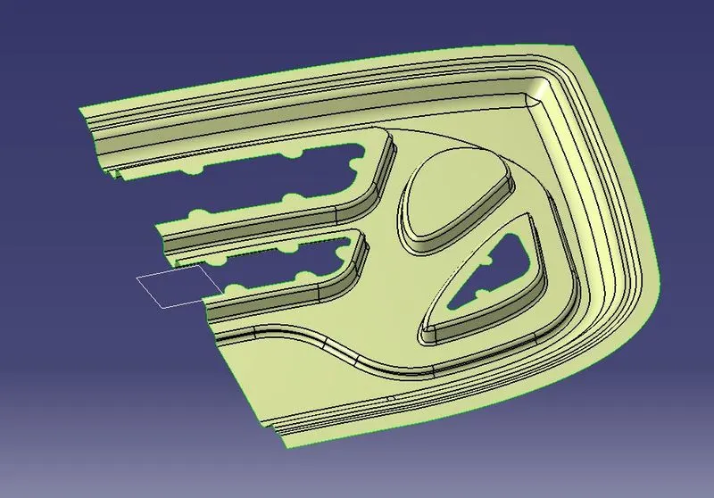
3. Creation of Cut-outs.
The cutouts are mainly created in order to reduce adult and child head damage during a collision. the spots for Mastic points are also cut out.
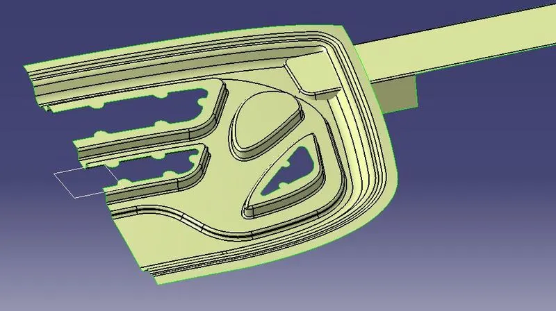
4.Create Embosses/Debosses for Hinge and striker.
To facilitate the hinge mounting points, Embosses are created with a flat base so that the hinges and lie flat onto the mounting points.
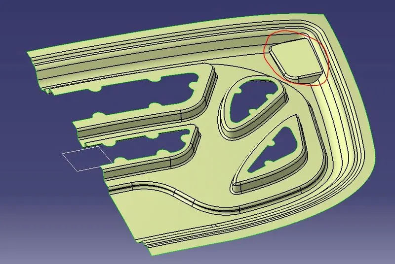
Creating the striker mounting point.
The Trajectory of the Striker is created along the Hinge axis. This is done in order to determine where the Striker gets mounted onto the Inner Panel.
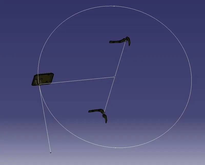
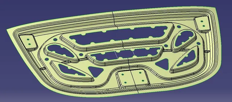
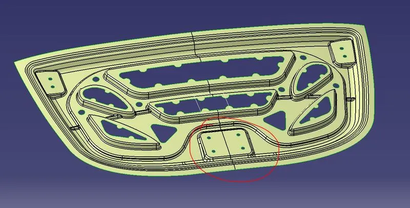
Once the mounting point is decided, the embossed are made on the Inner Panel for the Striker to be positioned.
DRAFT ANALYSIS OF THE INNER PANEL:
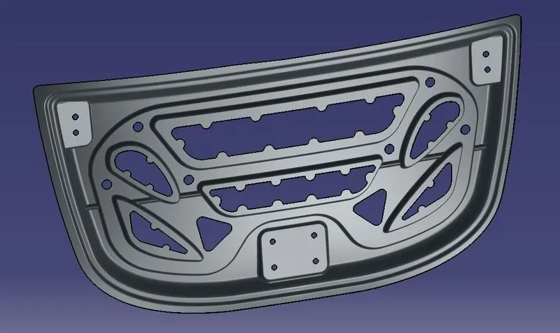
THICKENING OF THE INNER PANEL:
The inner panel is thickened to a thickness of 0.75mm.
CRUMBLE ZONE FOR THE INNER PANEL:
The front and rear crumple zones of a car are designed to collapse at a force which transmits a 20g horizontal deceleration to the rigid passenger cage. During a frontal impact, the seat cushion shears because the seat belts do not restrain body motion until their slack is taken up. A lap seat belt can only restrain the pelvis if the body does not sink excessively in the seat. Submarining occurs if the person sinks and moves forwards in the seat, and the seat belt rides up onto the soft organs of the stomach and liver. The use of firm seat foam is ruled out by the requirement in the last section. The problem can be partly solved by providing rigid steel beams at the front of the seat, so that when the body slides forwards, it is forced to rise.
HEMMING OF THE OUTER PANEL:
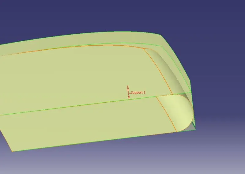
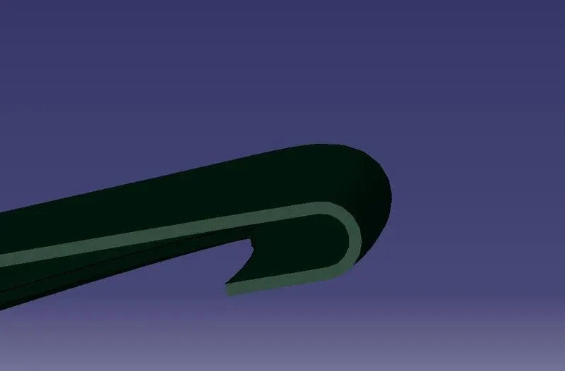
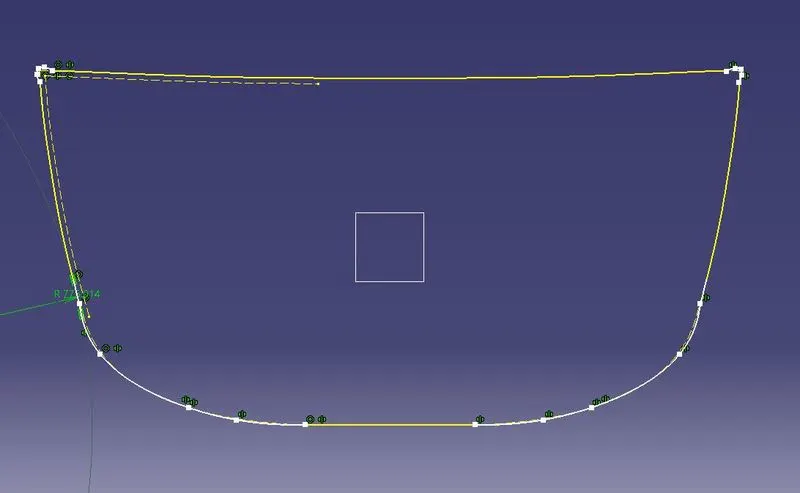
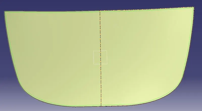
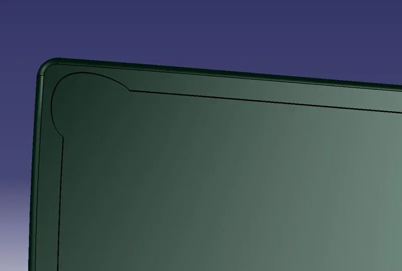
The Hem was created by using the Tritangent fillet option.
HEMMING RELIEF CUTS/ANGLES:
THICKENING THE OUTER PANEL:
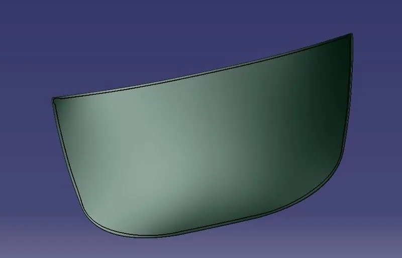
The outer panel is thickened to a thickness of 0.75
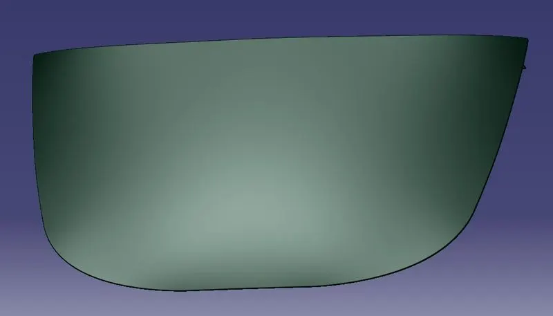
FRONT VIEW:
INNER VIEW:
REINFORCEMENTS:
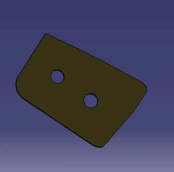
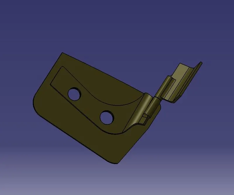
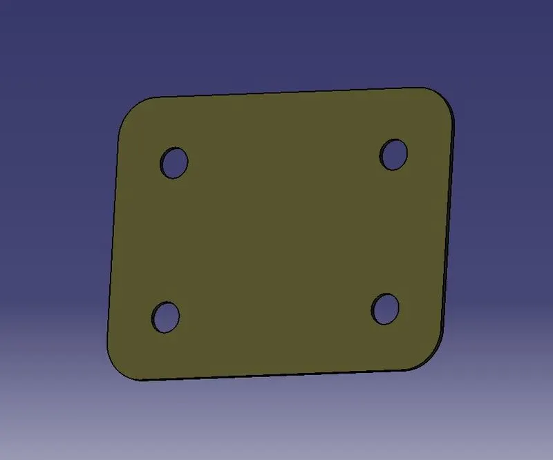
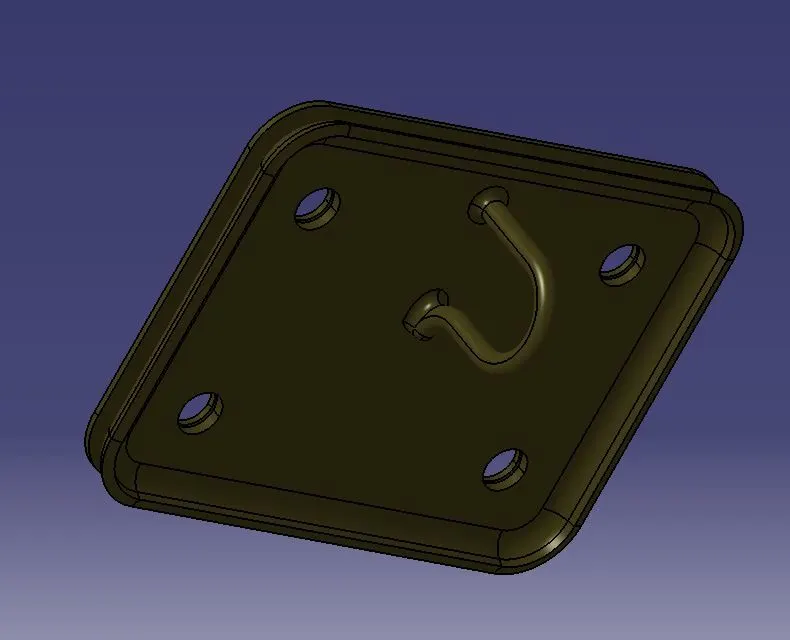
The hinges and the striker are components which are subjected to loads. due to this, the inner panel may be experience deformation. hence, reinforcements and the respective component are placed on either sides the inner panel.
- Reinforcement Thickness = 1.5mm
- HINGE REINFORCEMENT.
- STRIKER/LATCH REINFORCEMENT:
FINAL ASSEMBLY:
The final product is created and is ready testing and production.