Hood design-Week 2
Aim: Design of Hood Assembly
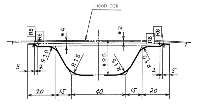
Objective: To create the Hood assembly from the styling surface and master section details provided using NX CAD.
Introduction:
HOOD: It is a material that covers the engine portion of motor vehicles. It can be opened so that to carry out any maintenance and repair work.
Benefits:
- Helps in minimizing damage to pedestrians and also to the passengers.
- It helps to minimize pressure on the windshield.
- Helps for aerodynamic flow.
Parts included in Hood Assembly:
- Outer Panel
- Inner Panel
- Latch & Striker Plate
- Hinges
- Reinforcement
Sheet Metal Operations carried out:
1) Blanking: It is a cutting process in which sheet metal is removed from the large sheet through shearing force applied on the sheet. The removed material is called 'Blank' which is the desired part shape.
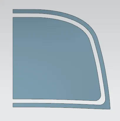
2) Piercing: It is a cutting process in which sheet metal is removed from the large sheet through shearing force applied on the sheet. The retained part is the required part whereas the removed portion is scrap.
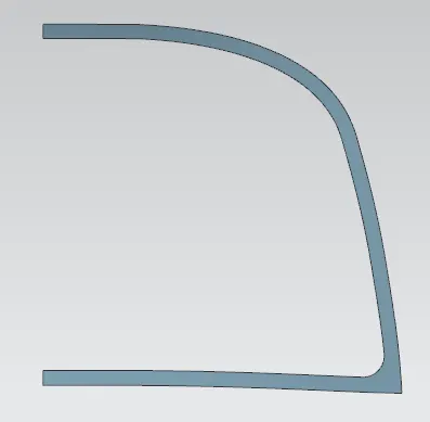
3) Deep drawing: It is a sheet metal forming process in which a sheet is drawn into the hollow part of the desired shape by the combination of tensile and compressive forces.
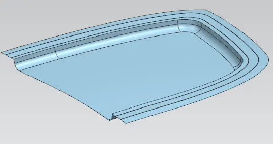
3) Emboss: It is a stamping process of producing raised/sunken designs on sheet metal. There will be no change in sheet metal thickness during this process.
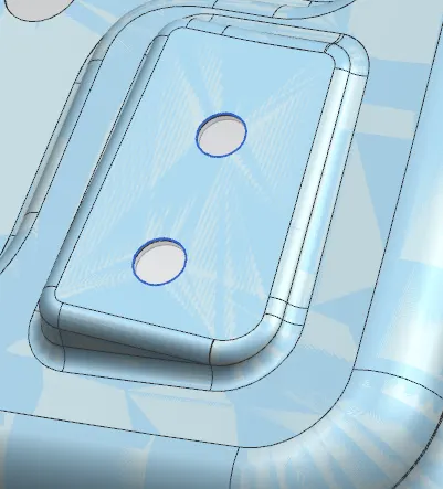
4) Hemming: It is a metal forming process in which the sheet is bent itself to 180 degrees. It is performed to hide the burrs and sharp edges of the sheet and to improve the appearance.
Data Provided for Hood Assembly:
Outer Panel Thickness = 0.75mm
Inner Panel Thickness = 0.75mm
Reinforcement Thickness = 1.5mm
Master Section:
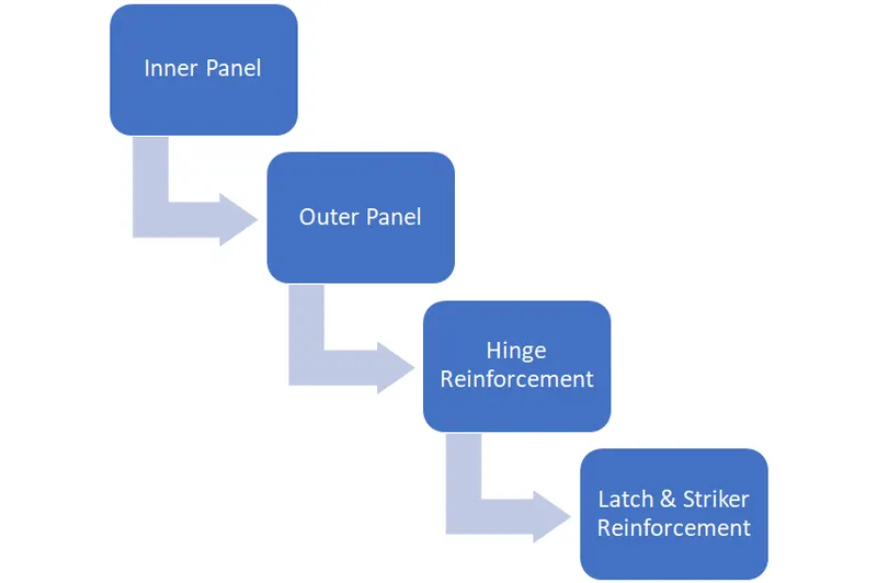
Design Methodology:
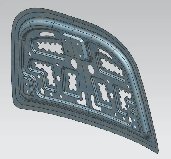
Inner Panel:
Styling surface is used as a reference and it is offset to the desired distance and then operations are carried in order to get the required dimension of the panel.
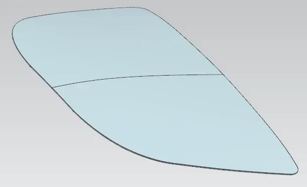
Outer Panel:
It plays an important role that covers the inner panel and also gives a look to the vehicle.
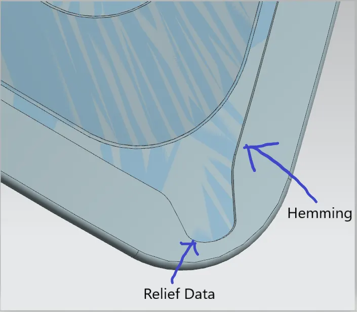
Hemming and Relief Data:
Hemming operation is performed in order to hold the outer and inner panels together.
Relief Data is provided in order to reduce the stresses that may occur at the sharp corners and other areas.
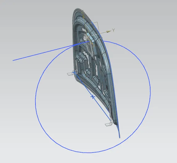
Trajectory path Sketch: It plays a very important role as the striker has to match with the latch in the engine compartment otherwise hood will not get properly locked.
Once the hinge is placed in the inner panel, the hinge axis is drawn between two hinges then a circle is drawn from the center of the axis line and the tangent line is drawn. The trajectory line and striker line should be on the same path.
Hinge Assembly:
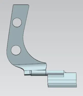
Striker Plate:
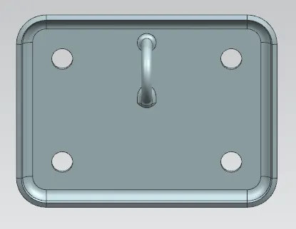
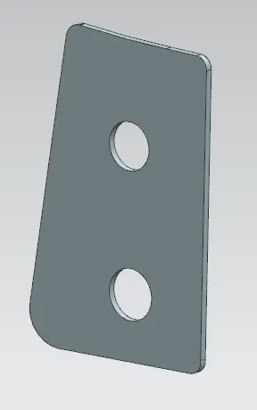
Hinge and Striker Reinforcement:
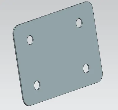
In order to avoid the NVH problem that occurs at the hinge and striker portion, additional reinforcement is provided at the hinge and striker. Reinforcement is provided inside the inner panel of thickness 1.5mm.
Hinge Reinforcement
Latch and Striker Reinforcement:
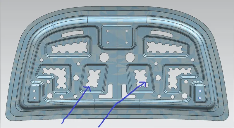
Mastic Data Design:
As spot welding cannot be done on the outer panel, mastic sealants are used between the inner and outer panels so that they are held together. They are usually in rubber form which is applied on the specified mastic dots provided gets hardened after going through a hot furnace bath. They will provide strength from the inside portion and have a tendency up to 80mm diameter.
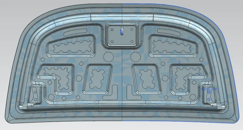
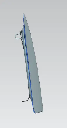
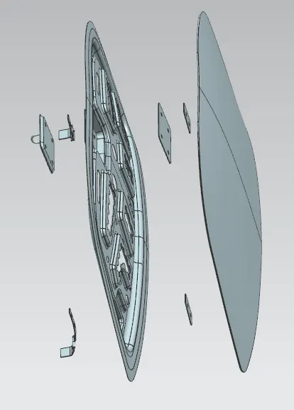
Hood Assembly
Front View
Top View

Side View
Exploded View
Conclusion:
Hood assembly is designed according to EURO NCAP safety protocols using NX CAD.