Hood design-Week 2
Objective:
In this project i am going to design car hood inner panel by using Nx cad and which is helps to get familiar with the Nx cad options , features and tools and also going to learn what are the design parameters and the engineering skills required to make the hood.
Introduction:
Here i am going to understand and design the concept of front mounted engine hood according to the OEMs standards. The hood and bonnent is the cover above the engine of motor vechicles that allows access to the engine compartment, or trunk for maintenance and repair.
on front mounted engine cars, the hood may be hinged at either the front or the rear edge, or in earlier models, it may be split in two sections, one each side, each hinged along with centerline. A future variant combaines the hood and the wheel areches into one section and allows the entire front body to tilt forwards around pivot near to the front vehicle.
i am used siemens NX 12 version software is used here.
pedestrain - vechicle collision:
The science and engineering involved in understanding vechicle -pedestrain collisions can be complex. From vechicle dynamics and injury causation, to contributing factors associated with human performance and roadway design, there are many potential factors to consider in any given incident.
Engineering modifactions generally can be classified into 3 board categories separation of pedestrains from vechicles by the time or space, measures that increase the visiblity and conspicuity of pedestrains and reductions in vechicle speeds.
mastic sealent:
The Mastic selant or the mastic point is an elastic compound that behaves like a rubber. The mastic points are defined on the hood inner panel where the hood can easily deform. They help the hood outer panel to come back to its orginal shape after it gets deformed.
Mastic area:
Deep Drawing:
Deep drawing is one of the most widely used processes in sheet metal forming. Apart from its use in many other sectors, it is applied in the automative industry for the manufacturing of car body parts. Process definition: The Deep drawing process is a forming process which occurs under a combination of tensile and compressive conditions.
A deep drawing of sheet metal is performed with punch and die. The punch has the desired shape of the base of the part. once drawn. The die cavity matches the punch and it is litter wider to allow for its passage, as well as clearance. For many calculations the sheet metal thickness is remain constant. However, there are some thickness changes in thickness in certain areas, due to the forces involved.
DESCRIPTION:
Hood Thickness information:
Outer panel Thickness = 0.75mm
inner panel Thickness = 0.75mm
Reinforcement Thickness = 1.5mm
Features and tools used for this model:
1)Sketch
2)Offset surface
3)Offset curve in face
4) Through curves
5) Trim sheet
6) Trim and extend
7) Law extension
8) face blend
9) extend sheet
10) edge blend
11) Face blend
12) mirrior geometry
13) emboss
14) sew
15) Thicken
Offset surface:command to create an offset of one or more existing faces. The result is a new body
Offset curve in face:Use this command to create offset curves on one or more faces from connected edges or curves on the surfaces.
Through curves:Creates a body through multiple section were the shape to pass through each section.
Trim sheet:Use the trimmed sheet command to trim sheet bodies to intersecting faces and datums, and projected curves and edges.
Trim and extend:This option lets you extend and trim one or more surfaces using a set of tool objects composed of edges or surfaces.
Law extension: Use the law extension command to extend an existing surface or sheet based on laws for distance and the angle of the extension.
Face blend: use The face blend command to add tangent blend faces between two or three sets of faces. The cross section of the blend can be circular, coinic, or law controlled.
Edge blend: Edge Blend command in siemens Nx is very versatile command to obtain blended edged or filleted edges in various shapes.
Mirrior geometry: The mirrior is taking the entire body and mirrioring it across. Whether its surface or a body solides.
Emboss: in the siemens nx modeling, emboss command use to create an embossing by modify a body with faces made by projecting a section along vector , with options for end cap location and shape.
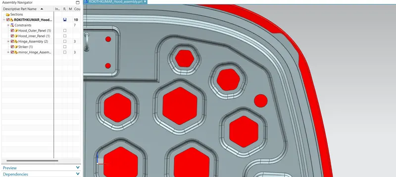
Sew:use the sew command to join two or more sheet bodies in to a new single sheetbody. if the collection of sheet bodies encolses a volume, a solid body is created. The selected sheet bodies must have any gaps larger then specified tolerance, or the resulting body will be a sheet body.
Thicken:Use the Thicken command to offset one or more connected faces or sheets in to a solidbody. Thickening occurs byoffsetting the selected faces along their face normals, and then creating sidewalls.
Hemming in sheet metal:
Hemming and seaming are two similar metal working processes in which a sheet metal edge is rolled over on itself. Hemming is the process in which the edge is rolled flush to itself, while a seam joins the edges of two materials.
Hems are commonly used to reinforce an edge, hide burrs and rough edges and improve apperance.
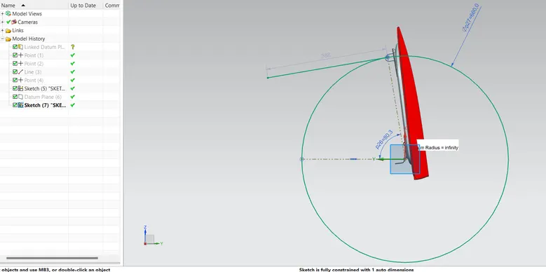
Latch trajectory: It is a calculation done on striker part were the hood opening and the colsing axis is drawn, For opening and closing the hood and the latch should be in proper axis so that is fixed and locks in to the latch lock. For creating the axis we use the latch trajectory.
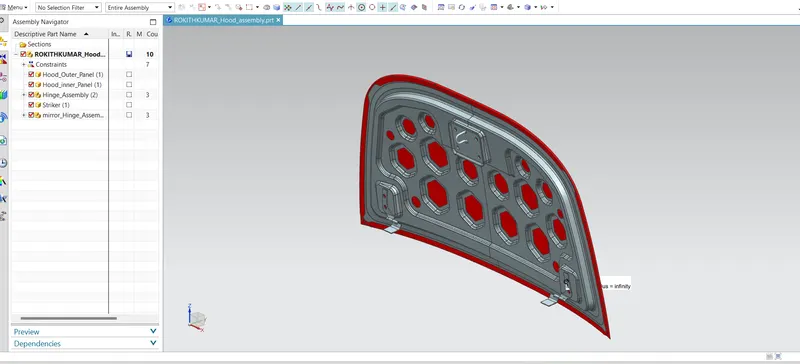
Assembly:
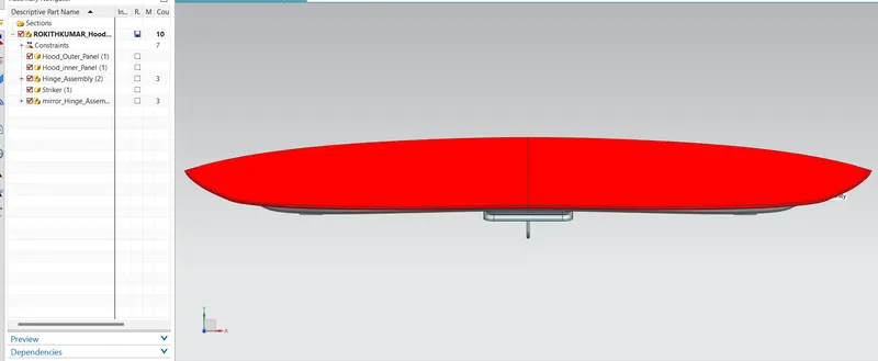
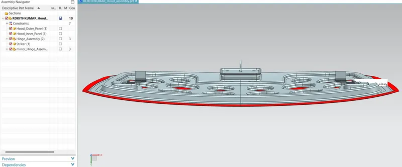
1. Insert all the parts and add them with the proper geometric assemble consrtains.
2. Create a latch trajectory so that the hood can closes and opens in a perticular axis.
3. To create a axis select the points on the oppossite two hinges respectively and create one line by using the two hing points
4. Then with respect to the axis create a datum plane on the center of the axis and draw a circle which represents the latch axis.
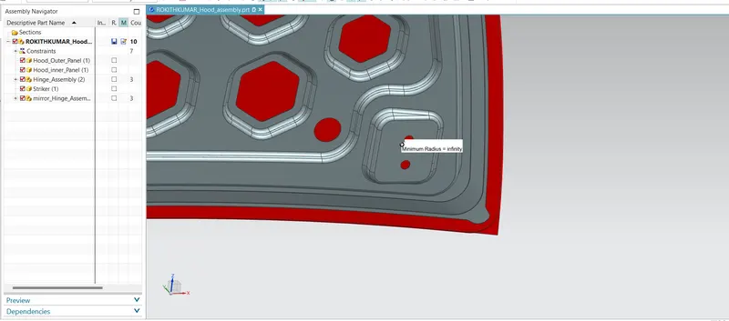
Reinforcement: when we create an emboss we need to add some reinforcement which will compensate the lose strength. We add the stiff pad to it so that it gets the strength and also it has some mastic point.
Views:
Front view:
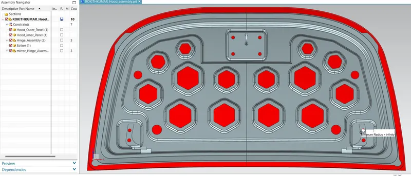
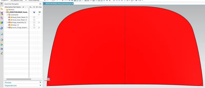
Top view:
Bottom view:
Back view:
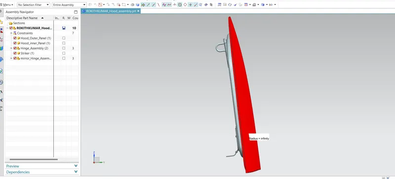
side view:
isometric view:
Conclusion:
Thus the automative car hood design has been designed and assembled by using constraints with Nx CAD.