Hood design-Week 2
Hood design in UG NX
Objective:-
Design hood outer pannel, inner pannel and reinforecement with the given outer hood skin,master section and design parameters.
Introduction:-
The hood or bonnet is the hinged cover over the engineof motor vechile. hoods can open to aloow access to the engine compartment(or trunk on rear-engine and some mid- engine vechiles ) for maintance and repair. In design perspective hood should meet some spacific condition like pedistrain saftey, hood head zone for lock sticker, force distribution when subjected to frontal collision, manufacturability ect...
- A perfect hood design means it should have a great impact distribution angled outside the car.
- In Japan and Europe, regulations have come into effect that places a limit on the severity of pedestrian head injury when struck by a motor vehicle. This is leading to more advanced hood designs, as evidenced by multicore hood inner panel designs.
- European Enhanced Vehicle-Safety Committee (EEVC), European New Car Assessment Program (euro NCAP).
Pedistrian- vechile collion:-
- India, however, ranks 1 in the number of road accident deaths across the 199 countries reported in the World Road Statistics, 2018 followed by China and the US. As per the WHO Global Report on Road Safety 2018, India accounts for almost 11% of the accident-related deaths in the World.
- Road transport remains the most favored mode of transport for both freight and passenger movement in India. The fast-growing population, exceptional rate of motorization coupled with the ever-growing urbanization has made people vulnerable to frequent road accidents resulting in fatalities, injuries/disabilities.
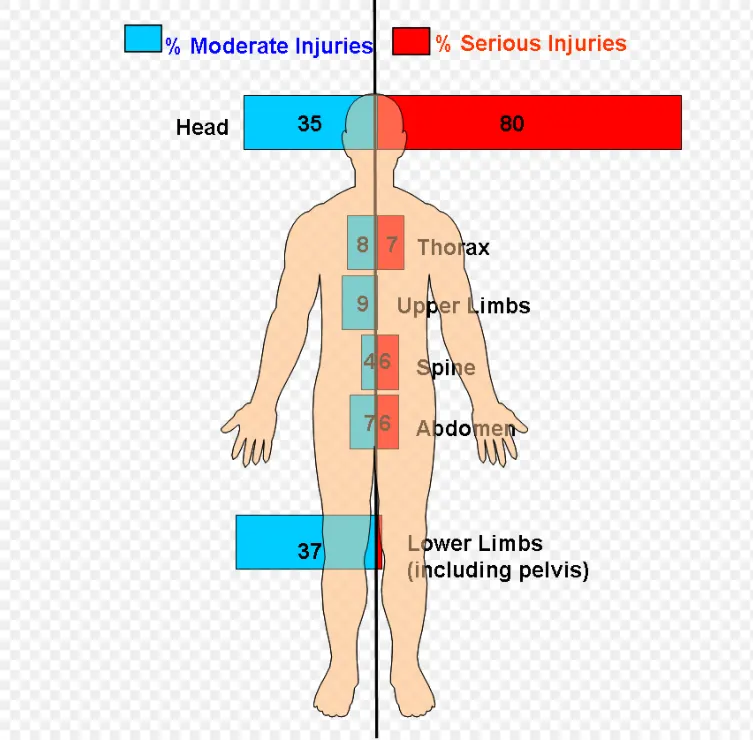
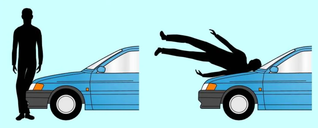
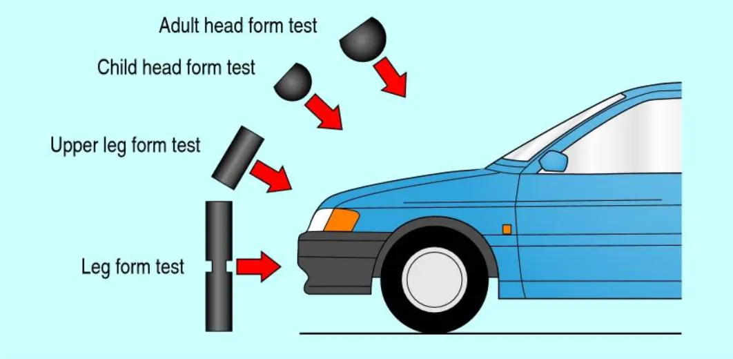
- the sequence of injuries and events in a pedestrian collision images are mentioned below.
Design parametrs :-
Hood thick ness information
Outer pannnel thickness = 0.75mm
Inner pannel thickness =0.75 mm
Reinforcement thickness = 1.5mm
Master section
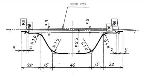
Important Features used in designing:
- Trim Body – It is used to trim one or more bodies using a face or plane. You can also specify the bodies to retain and the bodies to discard.
- Offset Surface – It allows you to offset one or more existing surfaces.
- Offset in Face – This command will allow you to offset particular edges or curves on selected faces.
- Trim Sheet – It is used to trim off a portion of a sheet body using curves, faces, edges or planes.
- Through Curves – It will allow you to create a body Through multiple sections, where it’s shape changes to pass through each section.
- Law Extension – This command extends a curve or edge to create a sheet body at desired angle length by changing the rules under angle law and length law.
- Trim and Extend – It helps you to trim and extend intersecting surfaces and make corner at their intersection.
- Face Blend – It creates fillets between faces.
- Edge Blend – It creates fillets on edges.
- Extend Sheet – It will allow you to extend an existing surface to required distance.
- Emboss – Emboss command creates an embossing by modifying a body with faces created by projecting a curve/section along a direction. You can modify the emboss using options like endcap location and draft angle.
- Projected Curve – It is used to project an existing curve/curves on a selected plane or surface by selecting a direction for projection.
- Mirror Geometry – As name suggests, it allows you to mirror geometries about selected plane or surface.
- Sew – It combines sheet bodies together by sewing their common edges. There shouldn’t be any gaps larger than specified tolerance.
- Thicken – It is used to convert a surface to solid body by providing thickness.
- Extrude – It helps you to create a feature from a sketch. You are also able to create thin feature using a sketch or curve under this command.
- Wave Geometry Linker – With this you can create, associative or linked copies of any entity of a part into other parts. It may be a surface, edge, curve, body, sketch etc. The changes made to the original entity will be reflected in the copy of that entity.
COMPONENTS:-
1.Hood outer pannel
Outer pannel are the aestheic element of a car. It is the styling team who provides the skin for the outer panel. The shape, position and size of the hood should satisfy the safety norms. So while designing the hood we should give more importance to pedestrian safety. The outer panel is attached to the inner panel by hemming. So, it is necessary to provide required hemming flange and reliefs for the hemming operation. We also provide mastic sealants between outer panel and inner panel to reduce vibration.
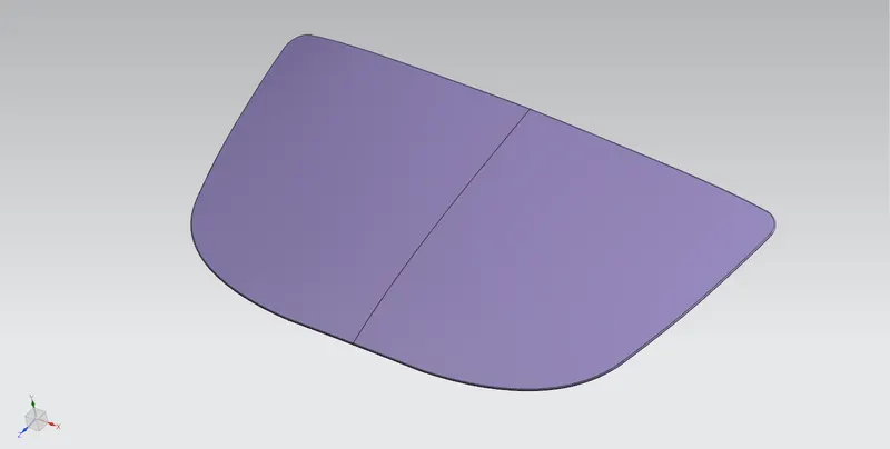
fig 1.1 :outer pannel
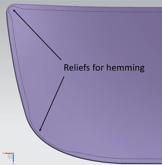
fig 1.2 :reliefs for outer pannel
2.Hood inner panel
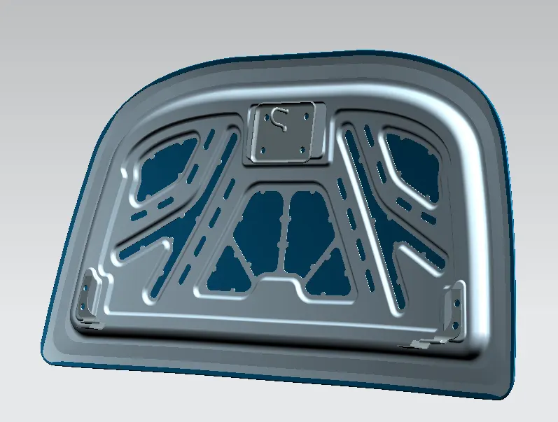
Inner panel is the part that gives strength and rigidity to the outer panel. The master section represents the initial emboss shape and size. Then we provide the emboss for the latch and hinge elements after fixing the location.
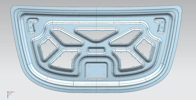
Fig 1.3: Hood inner panel
3.Reinforcement
Reinforcements are provided according to the design requirements. Mainly it is provided at the hinge and latch regions to improve the strength locally. Usually thickness of reinforcements will be higher than that of the inner panels and the value varies according to cost and requirement. According to the design requirement here it is given 1.5mm thickness to both hinge and latch reinforcements.
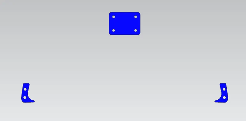
Fig 1.4: Hinge and latch reinforcement
4.Latch Trajectory
Latch trajectory is given by the circle drawn from the hinge axis point. Hinge axis point is the centre point of the hinge axis. First, we can fix either the latch or the hinge. If we have fixed the hinge position then we should plot the Trajectory circle for the latch. For proper mating condition the striker axis through the tip of the striker should be tangential to the latch trajectory.
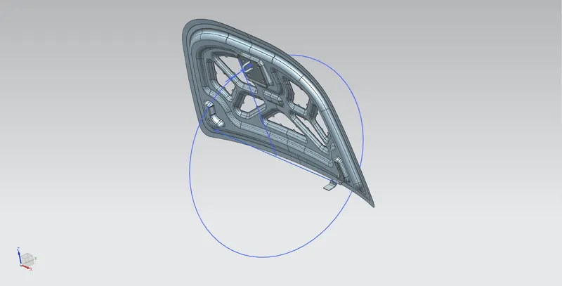
Fig 1.5: Latch trajectory
5.Emboss definitions
Throughout the inner panel we provide different embosses. We can increase the stiffness of the inner panel through these embosses. The shape and size of the embosses also determines the direction of the force distribution resulted from frontal collision. The force should be always distributed away from the passengers. Here in the figure the embosses are designed in such a way that the force is directed to either sides of the car.
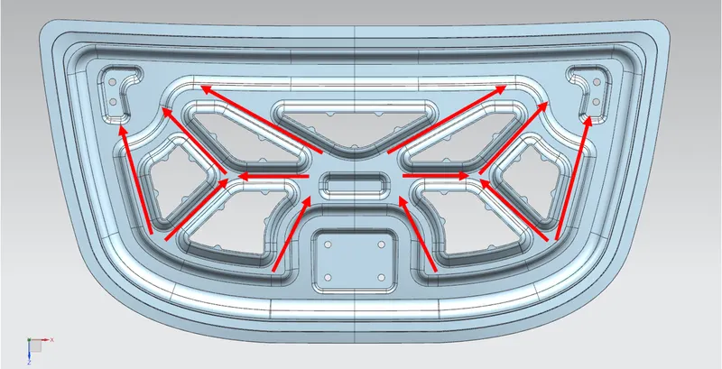
Fig1.6: Inner panel embosses
6.Mastic Data
Hood commonly possess large surface area and hemming can only be provided through its boundary. We cannot use other joining techniques like welding, riveting etc because they leave marks on the outer panel which spoil its aesthetic appearance. So, mastic sealants are used to stick the inner surfaces of outer panel and inner panel. Mastic sealants are elastic compound that behave like rubber. It is applied between the inner and outer panels at specified spots. Each spot of mastic sealants has its effect around a circular region of 80mm diameter. Thus, the mastic points are arranged in such a way that it covers the areas away from the hemming which are more vulnerable to vibrate.
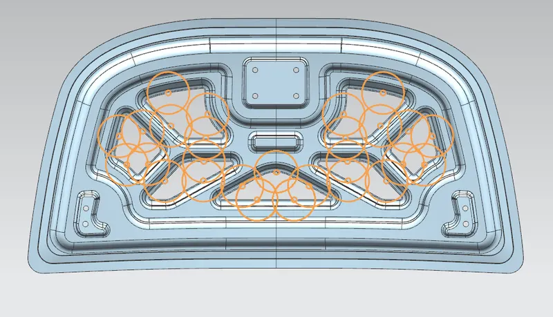
Fig 1.7: Mastic regions
7.Deep Drawing
Deep drawing is one of the most widely used processes in sheet metal forming. Apart from its use in many other sectors, it is applied in the automotive industry for the manufacturing of car body parts. The deep drawing process is a forming process which occurs under a combination of tensile and compressive conditions.
Sheet metal blank is radially drawn into a forming die by the mechanical action of a punch. It is thus a shape transformation process with material retention. The process is considered "deep" drawing when the depth of the drawn part exceeds its diameter. This is achieved by redrawing the part through a series of dies. The flange region (sheet metal in the die shoulder area) experiences a radial drawing stress and a tangential compressive stress due to the material retention property. These compressive stresses (hoop stresses) result in flange wrinkles. Wrinkles can be prevented by using a blank holder, the function of which is to facilitate controlled material flow into the die radius.
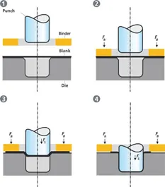
fig 1.8: deep drawing
8.Hemming
Hemming is a forming operation in which the edges of the sheet are folded or folded over another part in order to achieve a tight fit. Normally hemming operations are used to connect parts together, to improve the appearance of a part and to reinforce part edges.
In car part production, hemming is used in assembly as a secondary operation after deep drawing, trimming and flanging operations to join two sheet metal parts (outer and inner) together. Typical parts for this type of assembly are hoods, doors, trunk lids and fenders.
The accuracy of the hemming operation is very important since it affects the appearance of the surface and surface quality. Material deformations, which occur during the hemming process, can lead to dimensional variations and other defects in parts. Typical hemming defects are splits or wrinkles in the flange, material overlaps in the corner areas or material roll-in. This is why it is important to provide required reliefs at the corners.
There are two types of hemming operations,
- Conventional die hemming
In conventional die hemming, the flange is folded over the entire length with a hemming tool.
- Roll hemming
It is the roll hemming process that is used for automotive sheet metals. Roll hemming is carried out incrementally with a hemming roller. An industrial robot guides the hemming roller and forms the flange. Roll hemming operation can also be divided into several pre-hemming and final hemming process steps. Roll hemming is very flexible to use and tool costs are significantly lower as compared to those of conventional die hemming. However, the cycle times are much higher since the hemming is realized using a hemming roller which follows a defined path.
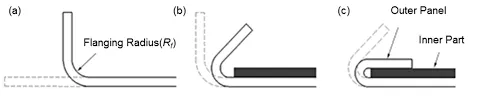
fig 1.9 : hemming process
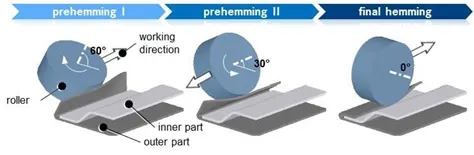
fig 1.10: Rroller hemming process on 3 stages
9.Final Assembly
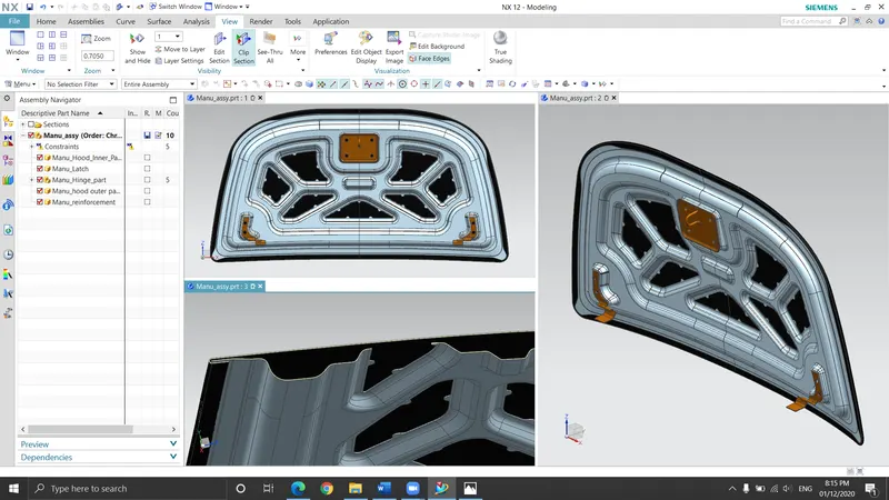
fig 1.11: hood assembly
conclusion:-
Thus i have designed hood along with the components and assembled the same, using NX CAD ,under given parameters.