Hood design-Week 2
Aim:
- To create a hood as per the Design Hood Outer Panel, Inner Panel and the necessary reinforcements by following the Master Section mentioned with the given Design parameters.
- And A detailed report about the Hood Design which includes a detailed explanation about hood and its components, Latch Trajectory, Mastic Data, Emboss Definitions, Manufacturing process like Deep-Drawing and Hemming, and all the parameters followed in the design.
Procedure:
- Download the Part files using the given link above and save all the parts in a single folder.
- .Prt files are used for NX
- Create a copy of the given outer panel in a new part and name it as inner panel.
- Trim the sheet using the centre plane and work on the part to achieve the master section.
- after achieving the master section, create emboses on the inner pannel.
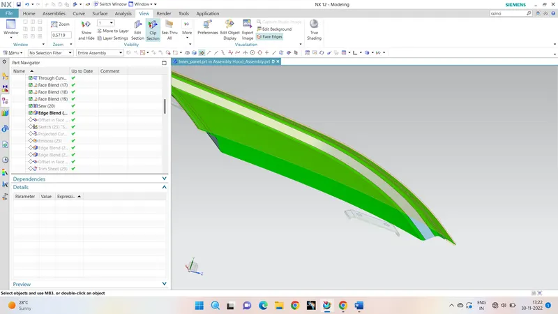
- The shapes of the sketches and emboses must be pointing toward the hinge reinforcements. It helps to distribute the force towards the hinges when car meets with any accident, that prevents the dashboard effecting from the force when the car hit to some object.
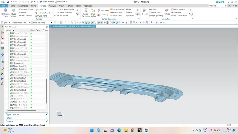
- After completeing the emboses make sure we have applied the blents using edge blents.
- Now making the outer panel as the working feature, offset the outer pane with 0mm distance and with offset and law of extension commands create the hemming for outer panel that wrap the edges of inner panel without intersections.
- Hemming is Hemming is a sheet metal forming process in which sheets are joined by bending.
- Thicken the entire created parts with 0.75 thickness as mentioned in the given data.
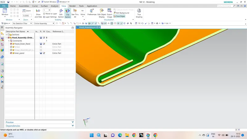
- The outer panel and the inner panel of the hood must not be intersected. the sectioned view is mentioned below:
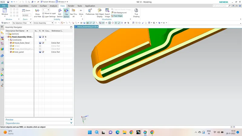
- After the hemming process the relief is given to the corners matching the data given
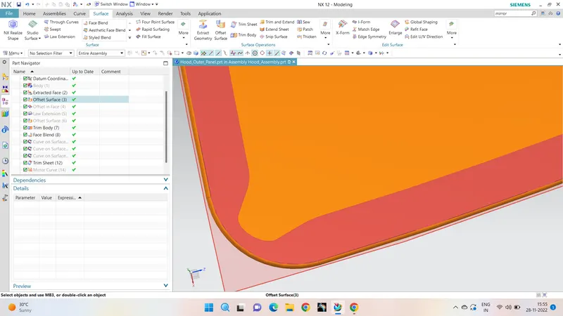
- The entire part is mirrored now using the mirror geometry command(we can find the command location in the search box) and both parts are sewed together to make it a single component.
Fixing hinge:
- A datum plane is created to place the hinge such that its angle must be infity
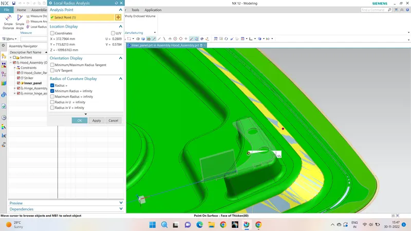
- Hinge is placed at the created datum plane and the emboss was created from the plane to the inner panel surface
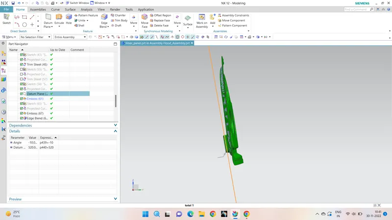
The placement of sticker is an important concept in this design, it must be in the tragectory angle with the hinge axis
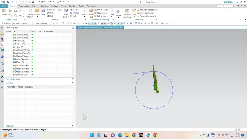
The stricker is assembled with the tangent line shown in the above picture and with the help of stricker geometry using wave geometry linker command and law of extension command the emboss is made and holes are made using the trim and extend command after placing the strickers in its position.
Here is the final assembly with all the satisfying Detailed design as mentioned in the question.
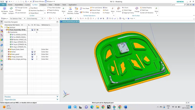
Hence the aim is achieved and zip file is attached below for the further detailed information.