Hood design-Week 2
AIM :
Design Hood Outer Panel, Inner Panel and the necessary reinforcements by following the Master Section mentioned with the Design parameters explained in the videos.
Submit an ASSEMBLY of Hood Inner Panel, Outer Panel, Latch, Hinge and the Reinforcements.
A detailed report about the Hood Design which includes a detailed explanation about hood and its components, Latch Trajectory, Mastic Data, Emboss Definitions, Manufacturing process like Deep-Drawing and Hemming, and all the parameters followed in the design.
The report should be well-formatted and should have a good flow of content. Add all the relevant images
Data to be used:
Hood Thickness Information
- Outer Panel Thickness = 0.75mm
- Inner Panel Thickness = 0.75mm
- Reinforcement Thickness = 1.5mm
Explanation
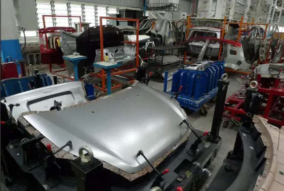
What is an Hood ?
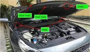
The hood (North American English) or bonnet (Commonwealth English excluding Canada) is the hinged cover over the engine of motor vehicles that allows access to the engine compartment, or trunk (boot in Commonwealth English) on rear-engine and some mid-engine vehicles) for maintenance and repair.

Types of Hood
1) Inlaid Hood or Built In Type : There is a gap between the hood and the car body as shown in the fig.1.1. Here the end point or the side reference line of the car lies on the fender , which uses more damge to the pedestrians and hence affecting their Euro-NCap ratings.
Fig.1.1.
2) Wrap Around Hood : These type tend to wrap around the car body as shown in the fig.1.2. Here the end point or the side reference line of the car lies on the Hood itself. This will reduce the head impact zone and hence can be able to achieve higher Euro NCap ratings. This is the most commonly used Hood type these days.
Fig.1.2.
Side Reference Line
The line from the ground at 45 degrees which is taken till the end point of the car. This is necessary to follow pedestrian Euro N-Cap assessment.
Fig.1.3. Fig.1.4.
The Side reference line on Inlaid Hood is shown in figure 1.3. & the Side refrence line for Wrap Around Hood is shown in fig.1.4.
Hoods can further be classified based on the Hood stay types :
1) Support Rod Hood Type
A hood stay is an apparatus for an engine room of a car , which can safely keep an engine hood in an open state if an external force is abruptly generated due to vibration, wind & can facilitate an opening/closing operation of the engine hood.
It Is the basic and most commonly used support for the hood in low cost and mid range cars, Since it is cost effective.
Fig.1.5.
The support rod used is slightly bent intentionally, as shown in fig.1.6. so that it adds strength & rigidity to the rod which can hold the hood effectively.
Fig.1.6.
Also there are restrictions to the design of the hood stay . The maximum distance a rod can be bent is less than 35mm. As shown in the Fig.1.7. And also the hood support rod should be fixed at the opposite end of the battery compartment enabling the ease of operation near the battery area.
Gromets are used to fix the support rod.
Fig.1.7.
2) Gas Stay Hood Type
Fig.1.8.
These type of Hood Support does not require much of Man power and is very useful when the weight of the hood is more and difficult to lift. This is usually seen in bigger cars and also it is expensive. These gas stays are provided in the back door to all car segements these days.
Fig.1.9.
It has two ends where one end is fixed to engine compartment and the other to the hood itself. The length C & D is kept constant and only the (B-A) length is varied. We could say that if the length of the Hood increases , (B-A) length also increses.
Stud ball is used to fix the gas stay support.
WHY DO WE NEED A HOOD FOR...?
The main function of the car hood is to protect the components underneath it for example, the engine. Without this protection, small stones kicked up by other cars could puncture a fluid container or damage the engine. In addition, most engines are not supposed to be exposed to excess water.
PEDESTRAIN SAFETY
Pedestrians are the most vulnerable road users who are at the high risk of vehicle collisions in traffic, Almost 1.2 million pedestrians are killed annually in road traffic accidents worldwide. The major injuries occur in lower, upper leg and head of the pedestrian, where the fatalities of the pedestrians in the accident is mainly due to head injury resulting from the hard impact of the head against the stiff hood or to the ground. In recent years, engineers are working on the vehicle front end design which includes bumper and hood to reduce the injuries to the pedestrians in the event of pedestrianvehicle collision.

Euro NCAP is a voluntary vehicle safety rating system created by the Swedish Road Administration, the International Consumer Research & Testing, backed by members, and motoring & consumer organisations in several EU countries.They provide consumers with information regarding the safety of passenger vehicles. In 1998, operations moved from London to Brussels.
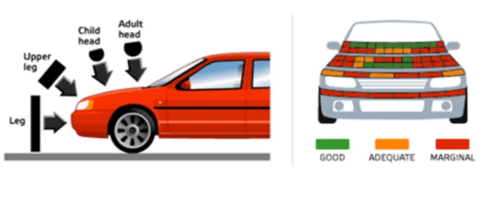
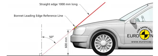
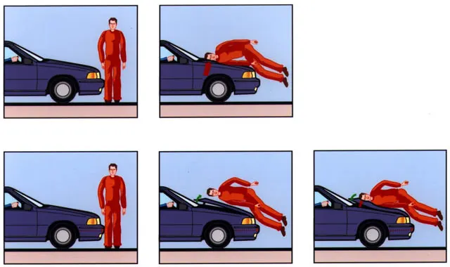
Many pedestrian crashes involve a forward moving car (as opposed to buses and other vehicles with a vertical hood/bonnet). In such a crash, a standing or walking pedestrian is struck and accelerated to the speed of the car and then continues forward as the car brakes to a halt. The pedestrian is impacted twice, first by the car and then by the ground, but most of the fatal injuries occur due to interaction with the car. Vehicle designers usually focus on understanding the car-pedestrian interaction, which is characterized by the following sequence of events: the vehicle bumper first contacts the lower limbs of the pedestrian, the leading edge of the hood hits the upper thigh or pelvis, and the head and upper torso are struck by the top surface of the hood and/or windshield.
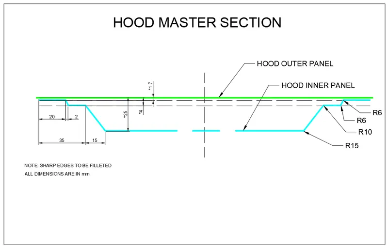
The input design for the hood inner panel is given below:
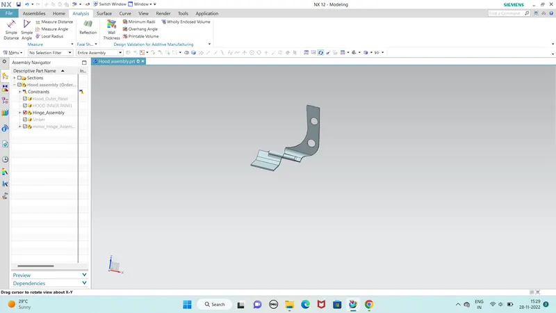
HINGE ASSEMBLY :
Hinges is the assembly of components connected to the door and body of the vehicle, linked to each other and capable of rotating around the same axis. Conventional system consists of two hinges for each door, an upper hinge and a lower hinge.
Hemming
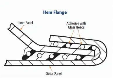
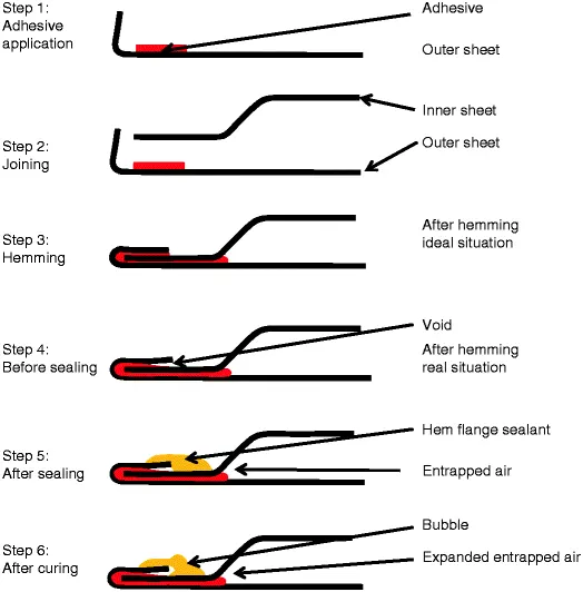
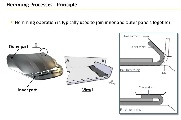
Hemming is a forming operation in which the edges of the sheet are folded or folded over another part in order to achieve a tight fit. Normally hemming operations are used to connect parts together, to improve the appearance of a part and to reinforce part edges.
In car part production, hemming is used in assembly as a secondary operation after deep drawing, trimming and flanging operations to join two sheet metal parts (outer and inner) together. Typical parts for this type of assembly are hoods, doors, trunk lids and fenders.
The accuracy of the hemming operation is very important since it affects the appearance of the surface and surface quality. Material deformations, which occur during the hemming process, can lead to dimensional variations and other defects in parts. Typical hemming defects are splits or wrinkles in the flange, material overlaps in the corner areas or material roll-in. This is why it is important to use simulation tools in order to, on the one hand, better understand the hemming process and, on the other hand, significantly reduce the number of “trial and error” loops during tryout und production.
There are various types of hemming operations:
Conventional die hemming
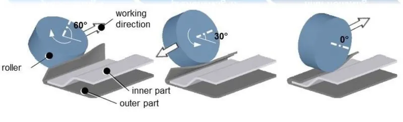
Roll hemming
In conventional die hemming, the flange is folded over the entire length with a hemming tool.
In roll hemming, the hemming roller is guided by an industrial robot to form the flange
Hinge Reinforcement
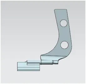
Devices for preventing movement between relatively-movable hinge parts for maintaining the hinge in two or more positions, e.g. intermediate or fully open the maintaining means acting perpendicularly to the pivot axis with a coil spring perpendicular to the pivot axis specially adapted for vehicles
The present invention concerns a hinged door check, for vehicle doors in particular, consisting of two hinged parts which are connected swivelling around an axis of rotation by a hinge pin and which have a holding device integrated between them defining different relative rotational positions. The holding device consists first of at least one catch element kinematically connected with the first hinged part and spring-loaded in a working direction perpendicular to the axis of rotation, and secondly of a track kinematically connected with the second hinged part , essentially shaped like the sector of a circle and arranged coaxial to the axis of rotation with respect to its radius of curvature, having at least one latching point cooperating with the catch element . The hinge pin is connected detachable from the first hinged part by fasteners , so that the hinged parts are separable when unloosening the fasteners while keeping the connection between the hinge pin and the second hinged part and the holding device assigned to the latter.
Stricker
t bolts to the underside of the hood at the front. It engages the hood latch when closed.
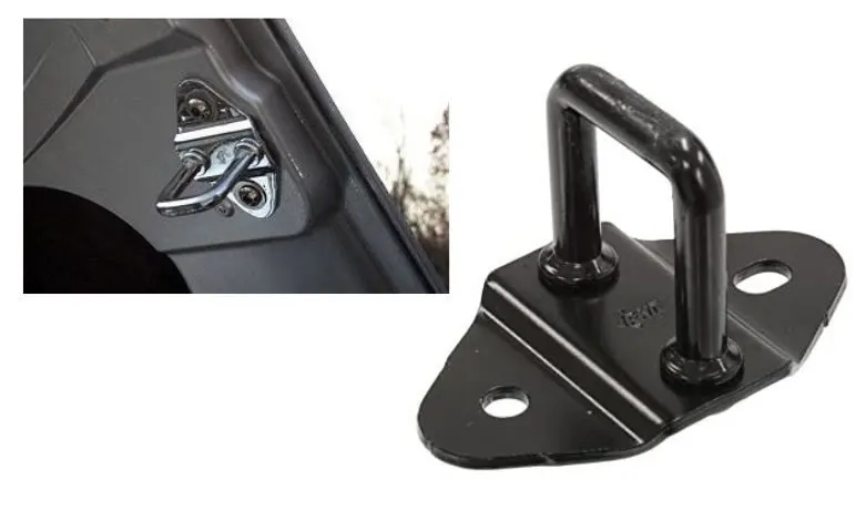
Latch and Striker
A latch or catch (called sneck in Northern England and Scotland) is a type of mechanical fastener that joins two (or more) objects or surfaces while allowing for their regular separation. A latch typically engages another piece of hardware on the other mounting surface. Depending upon the type and design of the latch, this engaged bit of hardware may be known as a keeper or strike.
A latch is not the same as the locking mechanism of a door or window, although often they are found together in the same product.
Latches range in complexity from flexible one-piece flat springs of metal or plastic, such as are used to keep blow molded plastic power tool cases closed, to multi-point cammed latches used to keep large doors closed.
NOTE:
Data to be used:
Input Parameters:
- Hood Outer Panel
- Master Section Sketch
Hood Thickness Information
- Outer Panel Thickness = 0.75mm
- Inner Panel Thickness = 0.75mm
- Reinforcement Thickness = 1.5mm
These are the most important parameters we need to consider while preparing the HOOD
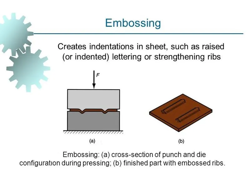
EMBOSSING & MASTIC POINTS:
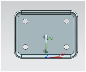
MASTIC JOINT:
Mastic is an adhesive that, along with thin-set mortar, is used to stick a sheet metal. While mastic does have strong points, such as great adhesive properties and adaptability to many substrates, high performance in wet areas is not one of its high points.
Sealants (sometimes called mastics) are used for waterproofing, such as repairing a leaking window. They are usually supplied in the form of a large tube with a nozzle at one end and may be either clear or black.
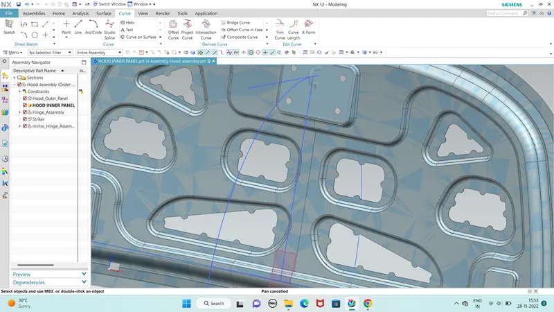
The above fig shows the how to give mastic point in the Inner pannel of Hood.
Mastics are used to join the Hood Inner pannel and Outer pannel.
The mastic point distances are 80mm.
Another main funcion of hood is HEMMING it is the most important to join the edges of hood.
Hemming is used in the car to resist the wear and tear of the hood.
For making a hemming we need to fallow some important parameters where to reduce the wear and tear of the hood.
If we not fallow the parameters of hemming and we got more noise of the hood when we are travelling.
Hemming Data:
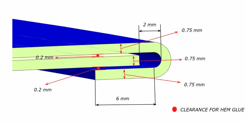
Hemming is a forming operation in which the edges of the sheet are folded or folded over another part in order to achieve a tight fit. Normally hemming operations are used to connect parts together, to improve the appearance of a part, and to reinforce part edges.
The above fig shows the hemming how to do and what are parameters we need to consider.
The given distance for the edges are used to reduce the weaar and tear and get friction.
Parts of a Hood
- Hood outer panel
- Hood inner panel
- Latch and Striker
- Hinge engine compartment
- Hinge hood part
CLASS A SURFACE :In automotive design, a class A surface is any of a set of freeform surfaces of high efficiency and quality. Although, strictly, it is nothing more than saying the surfaces have curvature and tangency alignment – to ideal aesthetical reflection quality, many people interpret class A surfaces to have G2 (or even G3) curvature continuity to one another (see free form surface modelling). Class A surfacing is done using computer-aided industrial design applications. Class A surface modellers are also called "digital sculptors" in the industry. Industrial designers develop their design styling through the A-Surface, the physical surface the end user can feel, touch, see etc.
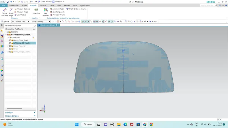
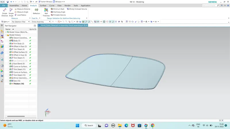
The above fig shows the outer pannel of the hood.
According to the Master section we need to draw the hood design and we need to fallow the master section.
So that we need to understand the master section and try to perform according to that.
First we want to offset the given model according to master section and now we want to perform the tools like offset face, offset curve, Trim sheet, Law extension, Emboss, Project curve and for the edges we use Edge blend or Face blend and we use Sew coomand to join the two parts.
The above mention tools are most important and with help of these commands we need to draw the sketch.
First we need to perform the half of the section and we need to mirror the object with thte help of Mirror Geometry.
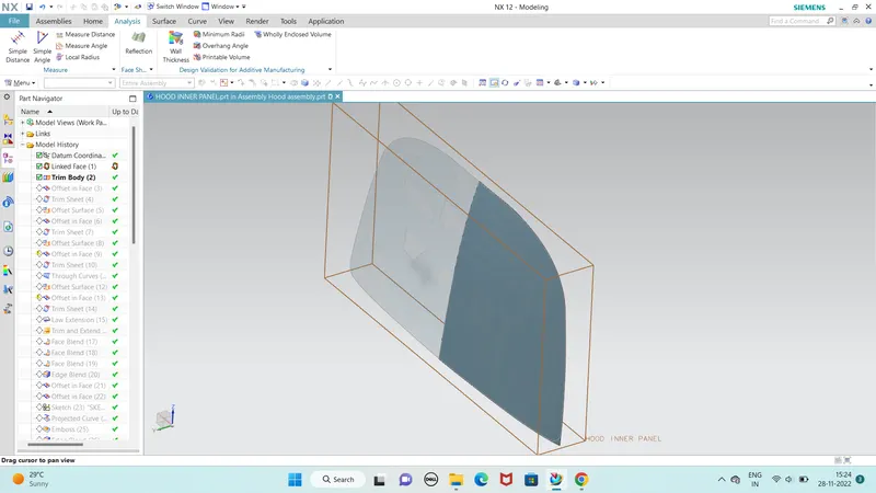
HOOD INNER PANEL :
First we want to offset the given model according to master section and now we want to perform the tools like offset face, offset curve, Trim sheet, Law extension, Emboss, Project curve and for the edges we use Edge blend or Face blend and we use Sew coomand to join the two parts.
The above mention tools are most important and with help of these commands we need to draw the sketch.
First we need to perform the half of the section and we need to mirror the object with thte help of Mirror Geometry.
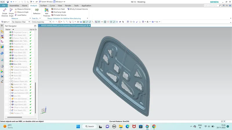
HOOD OUTER PANEL :
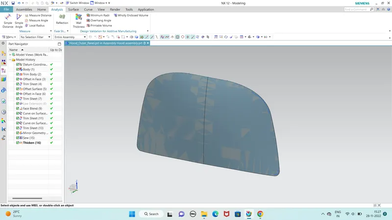
we need to same as the inner panel commands like offset in face, Trim sheet , law extension , and we perform the hemming surface to fix the inner panel.
HEMMING OPERATION :
Hemming is a forming operation in which the edges of the sheet are folded or folded over another part in order to achieve a tight fit. Normally hemming operations are used to connect parts together, to improve the appearance of a part and to reinforce part edges. In car part production, hemming is used in assembly as a secondary operation after deep drawing, trimming and flanging operations to join two sheet metal parts (outer and inner) together. Typical parts for this type of assembly are hoods, doors, trunk lids and fenders. The accuracy of the hemming operation is very important since it affects the appearance of the surface and surface quality. Material deformations, which occur during the hemming process, can lead to dimensional variations and other defects in parts. Typical hemming defects are splits or wrinkles in the flange, material overlaps in the corner areas or materia roll-in. This is why it is important to use simulation tools in order to, on the one hand, better understand the hemming process and, on the other hand, significantly reduce the number of “trial and error” loops during tryout und production.
There are various types of hemming operations:
Conventional die hemming :
Conventional die hemming is suitable for mass production. In die hemming, the flange is folded over the entire length with a hemming tool. Normally the actual hemming is a result of a forming operation in which the flange is formed with a hemming tool after the drawing and trimming operations have been completed. The formed flange is then hemmed in several process steps. These steps include, for example, the pre-hemming and final hemming depending on the respective opening angle of the flange. Production plants for conventional die hemming are very expensive, but the cycle times are very low.
Roll hemming :
Roll hemming is carried out incrementally with a hemming roller. An industrial robot guides the hemming roller and forms the flange. Roll hemming operation can also be divided into several pre-hemming and final hemming process steps. Roll hemming is very flexible to use and tool costs are significantly lower as compared to those of conventional die hemming. However, the cycle times are much higher since the hemming is realized using a hemming roller which follows a defined path. A corner reliefs are provided at the edges of hemmed part to provide corner reliefs.
HINGE ASSEMBLY :
Firstly in the inner panel we had create the emboss with with datum plane after we check the flatness of the surface, it has to be infinity.
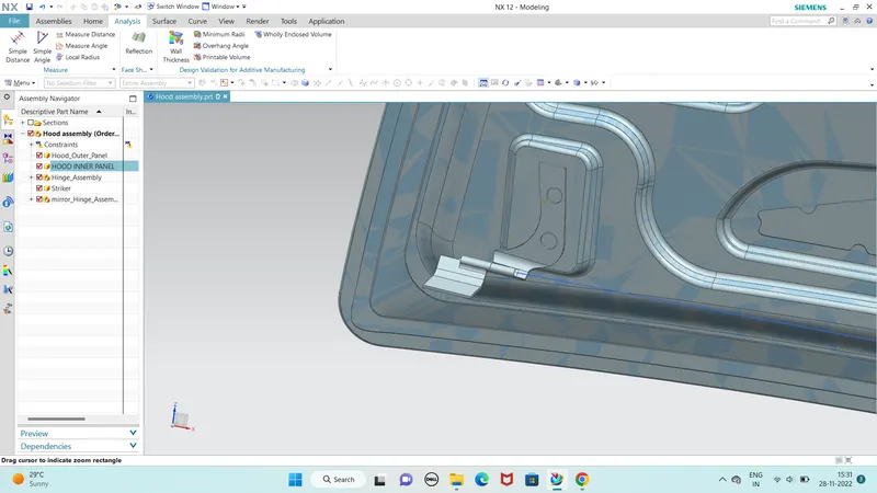
LATCH & STRIKER :
Latch & striker is used for locking the hood with the car. it's usually placed on the space provided on the inner panel.
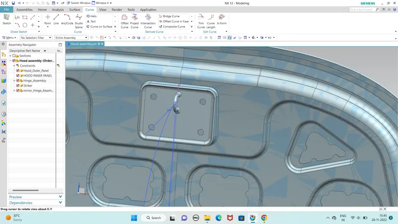
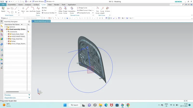
The latch/Striker is position from the basis of hinges centre point. Two points is marked from the two hinge axis and a line is drawn from the two points. A midpoint is taken from the line for positioning the latch
Now a circle is drawn as that point as a centre with a radius of approximately 300 mm(based on the hood designer) and the tagent line is drawn on that circle. Then latch is coincided with that tangent line.
So after latch position is fixed then the emboss is created from the latch surface using wave geometry linker in to the inner panel file. Striker emboss is shown in the below image.
DEEP DRAWING:
Deep drawing is widely-used in sheet metal forming, e.g. manufacturing of car body parts in the automotive industry. Details are given in the glossary.
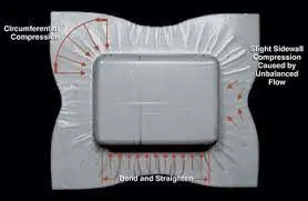
Deep drawing is one of the most widely used processes in sheet metal forming. Apart from its use in many other sectors, it is applied in the automotive industry for the manufacturing of car body parts.
Process definition:
The deep drawing process is a forming process which occurs under a combination of tensile and compressive conditions. A flat sheet metal blank is formed into a hollow body open on one side or a hollow body is formed into a hollow body with a smaller cross-section.
Deep drawing processes are divided into three types:
Deep drawing with tools
Deep drawing with active means
Deep drawing with active energy
In the automotive industry, deep drawing is usually carried out using rigid tools.
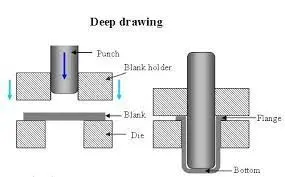
Illustration of the deep drawing process
The figure illustrates the deep drawing process. The rigid tools consist of a punch, die and binder. In deep drawing, the plate holder closes after the metal sheet blank has been inserted.
Next the sheet is clamped between the die and the binder. This process slows down the flow of the sheet while it is being drawn and thereby prevents wrinkles from forming under the binder. The punch stretches the sheet over the die radius and forms it in the die. The amount of punch force necessary for forming is thereby continually increased up to the lower dead center of the punch.
Whereas in pure deep drawing there is no reduction of sheet metal thickness, forming is achieved in stretch forming purely as a result of a decrease in sheet metal thickness. Stretch forming is extensively used for the forming of only slightly curved parts with low depth of draw (e.g. roofs, doors).
When drawing complex car body parts in practice, there is usually a combination of stretch and deep drawing involved. It is necessary that the sheet metal is stretched as well as possible without reaching the material’s limits (e.g. splits, wrinkles).
There are approximately 300 to 400 sheet metal parts which fit together to form the body of a car. In order to manufacture high quality sheet metal parts optimally for their particular use, specialized software simulates the complete deep drawing process.