Gopi Naik
What is industrial designQuestion-1 :
To Develop
- Industrial design sketches
- Concept & technology that will be used
To design a mechanism that can automatically move along vertical Y-axis [ Height ] for an
outdoor kiosk with a display.
[The product design for this assignment should also house a display & this display can be taken
from a sample model available from the internet.]
The sketches can be digital or analog.
Industrial designers balance creativity and usability and apply it to physical products for mass production. The industrial design process includes research, sketching, prototyping, and usability testing to ensure the product is perfect for production. Industrial designers typically improve upon an existing product by changing physical attributes or creating new product designs for new applications.
Industrial design sketching fundamentals
After completing all necessary research for a design brief, sketching is an affordable way to kick off the design process. It isn’t always essential to buy the most expensive gear for design sketching — a simple sketchpad and a pen, marker, or pencil will suffice. One of the most important initial requirements for an effective sketch is communicating perspective. Designers must showcase their design from multiple perspectives while utilizing two-dimensional and three-dimensional space to create realistic sketches. Along the same lines, designers can start with basic geometric patterns and expand on the design by implementing volumetrics and color.
Details are critical when sketching a product design. Form and function are first and foremost, with style and aesthetic appeal typically coming in second.
Product design sketching
Industrial designers can use several types of sketches depending on what they are trying to communicate to their team or client. For example:
- Ideation sketches are rough drafts consisting of basic shapes.
- Explanatory sketches explain functionality, structure, and usability. Designers often present explanatory sketches to the client or interested parties to help understand the end-product.
- Persuasive sketches are 3D sketches made in CAD software to emphasize color, shape, size, and details relevant to the customers’ appeal. This type of sketch is used to persuade the client or end-user to invest or purchase the product.
Each type of sketch is useful for different audiences, but the common theme is that they all express an idea. Remember that most industrial design sketches don’t need to be perfect works of art. Especially in the ideation phase, it’s ok to do quick, rough sketches as long as they communicate your idea.
Turning sketches into 3D models
Sketching is usually the first or second step in the industrial design process, depending on how much research is needed first. Whether you’re improving on an old design or creating a new one, it’s important to communicate design intention in a cost-effective and forgiving environment.
Industrial design sketches
- Once the designer and stakeholders select a final concept, the designer transfers the design into 3D modeling software.
- Software:- Autodesk Fusion 360 provides a cloud-based platform with integrated computer-aided design (CAD) and computer-aided manufacturing (CAM) software. Designers can leverage CAD software to render 3D models and alter product parameters digitally. Additionally, generative design in Fusion 360 uses artificial intelligence (AI) to test and improve products before prototyping.
THESE ARE SOME INDUSTRIAL DESIGN SAMPLE IMAGES I FOUND INTERNET
INDUSTRIAL DESIGNS
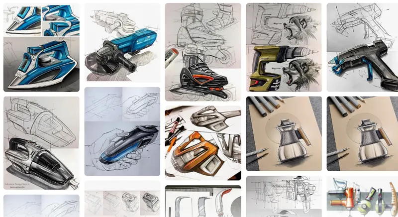
FOR MAKING A MECHANISM DESIGN WHICH CAN AUTOMAICALLY MOVING IN Y DIRECTION I MAKING A AUTOMATIC WHEEL CARRY LOAD CAR TO CARRIENG AND REPLACE THE OUTDOOR KIOSK DISPLAY IN ONE PLACE TO ANOTHER PLACE.
I AM SENDING MY PART OF KIOSK MODEL WHICH I’VE MADE IN SOLIDWORKS.

THIS IS ONE TYPES OF OUTDOOR KIOSK DISPLAY.
_________________________________________________________________________________
- Technical process flow with details on the selection of the Motor for the mechanism
Motor Selection- The motor selection process is not as simple as you might think. While selecting a motor, you will need to concentrate on many things e.g. Motor Speed, Motor Power Ratings, Motor load torques, Motor losses, Motor Efficiency etc. We will discuss all these factors in very detail. A motor selection can be easy and at the same time can be very difficult. Obviously, if you know about the different factors related with the motor selection then it’s easy for you, otherwise you may end up selecting a wrong motor
In this answer we have not indicated any particular requirement about speed nor have we said anything about starting condition, nor have we said anything about speed control. In fact we are simply content that the device is made to rotate.
If we consider many of the applications which we come across in everyday life, we find that we do not require anything special from a motor. For instance, within reason does the speed of a food mixer really matter or the speed of vacuum cleaner. For the food mixer, 300r/min us probably just as effective as 270 r/min. for electric drill it is normally starting of load so there are no problems getting it started. For the vacuum cleaner we not require to adjust the speed from 900r/min to 899 r/min.
Speed:
Most electric Motors operate at quite high speeds, say between 500 r/min and 3000 r/min. Special motors usually in association with power electronic systems which can operate at lower speeds or at higher speeds, but these are not especially common. Often it is easier to change speed by means of mechanical gears.
Most motors operate within small speed range e.g. an induction motor might operate between 1430 r/min and 1470 r/min according to load. At the extreme condition, a comparable synchronous motor would run at 1500 r/min regardless of the load. On the other hand commutator motor with series winding are able to accept wide speed variation as instanced by railway trains which seldom operate at constant speed such is the nature of railway operation.
In a number of specialist applications, precise speed control is essential. In the past, this requirement gave rise to a wide range of specially designed motors which were extremely complicated in their design they were a tribute to the ingenuity of engineer in time gone by. However improvements in power electronics systems have consigned such motors to the scrap yard and we will meet methods of controlling the speed of d.c shunt motors and cage rotor induction motors.
Power rating and duty cycle:
Basically, a motor is expected to operate continuously with a rated power output. The rating is dependent on the ability of the motors to dissipate waste heat. i.e the heat which comes from the loss in the windings, the eddy current losses in the rotor and stator cores and windage and friction. The losses cause the windings to become warmer and if the insulation gets too warm it will break down. Thus the rating depends on limiting the load such that it will not overheat the winding insulation.
The motors instanced are those which provide simple drives. Let us consider that would happen if a motor were cold and it were loaded to its rated value. It would not immediately heat to the maximum permitted temperature rather there would be a considerable period of time until that temperature was reached. The time would be in excess of an hour.
Alternatively, we could at the time of being cold have increased the load. This would have cause the motor to heat more quickly, but generally this is the acceptable so long as we do not continue with the overload beyond the time. When the maximum operating temperature is reached. This approach leads to short term ratings which assume higher loading followed by periods of switch off to allow cooling. Lift motors operate in similar load cycles.
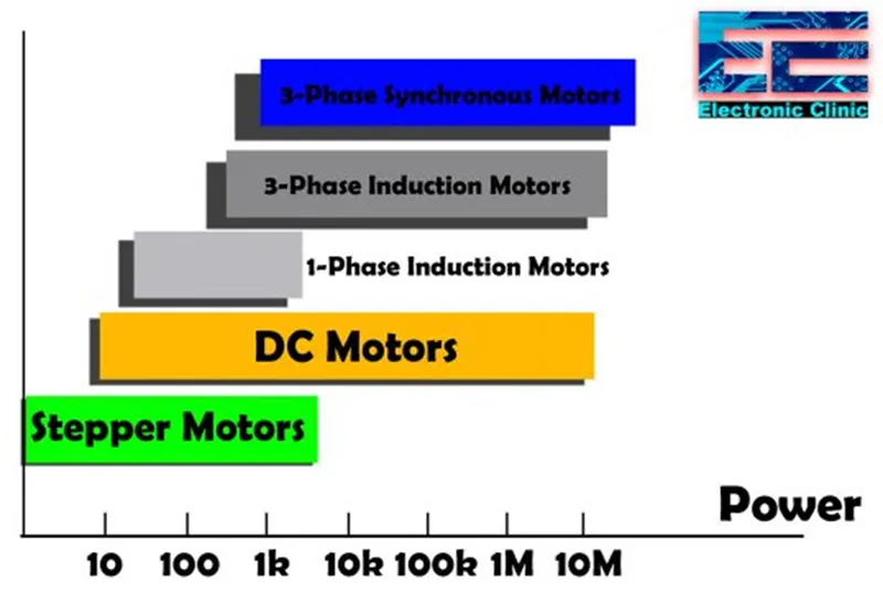
It is possible to use a 10KW motor to deliver 20KW for a very short period of time. Or for that matter to deliver say 11KW for 1 hr. motors for such cyclical duties are often available in standard forms for duty periods such as 10, 30 or 60 min. where there are shorter duty periods, motors are generally specifically designed for the intended applications.
There is quite a range of controlled-speed motors, but the two most common are the conventional dc motor and the variable frequency cage rotor induction motor. The dc motor has ratings between 100W and 10MW, while the induction motor almost the same rating.
Motor Load torques:
Load torques can be considered under two categories:
- Constant torque
- Fan or pump-type torque
The constant torque load can be instanced by the passenger lift. If we consider the arrangement. Let us assume loads causing a force of 5000 N in the lifting cable. If the lift were to rise at a speed of 1 m/s then the power required is 5000W. this requires that the motor produces 2πn1T , where n is the motor rotational speed and T the torque required. If the speed were to be doubled to 2 m/s. then the power would be 10000W= 2πn2T. However the rotational speed will be double to provide twice the rising speed for the lift hence we find that the torque remains the same i.e it is constant.
This description has not addressed the torque requirements during the acceleration and deceleration of the lift. To start the lift rising extra torque will be required the greater the desired acceleration, the greater the torque needed. Also we have the problem that the torque has to be produced even at standstill. Thus when we consider a so called constant torque load we are not taking into account the acceleration and deceleration period. The torque requirements for lift are shown:
We could have considered similar arrangements which involve horizontal motion, but most of these involve higher speed which introduce windage effects. For example a train quickly reaches a speeds at which the torque required is a mixture of the friction and the drive against the air through which it is moving.
Fans and pumps take the example of the train to the extreme and total load is only due to the drive against air (in the case of a fan) or against a fluid in the case of a pump. Usually the drive against air is proportional to the speed. Pumps have a similar characteristics, but the proportionality of the drive requires a higher power for the speed usually something approaching.
Both characteristics have the advantage that the motor hardly requires any torque at starting. In practice there is a static friction to overcome, so a practical load characteristics for a fan and that for an induction motor driving it take the forms. The difference between the motor and load torque shows there is a good advantage causing rapid acceleration to the operating condition.
The efficiency of a DC motor:
If Ra = total resistance of armature circuit
I = input current
Is = shunt current
Ia = armature current
The total loss in the armature circuit= I2aRa
If V= terminal voltage, loss in shunt circuit= IsV. This includes the loss in the shunt regulating resistor.
If C= some of core, friction and windage losses,
Total losses= I2aRa + IsV + C
Input power= IV
Output power= IV – I2aRa – IsV– C
Efficiency = IV – I2aRa – IsV – C
The motor and its environment:
When choosing a motor there is one factor which is independent of the circuitry of the motor the factor is the environment in which it is designed to operate. Towards this end there are four ranges of environmental activity which are considered:
- Ingress of materials
- Ingress of water
- Cooling arrangement
- Cooling power
Not all motors operate in a clean atmosphere although most operate in an atmosphere which contains nothing more than a little dust. There are international electro technical commission standards which provide for a range of levels of protection, starting with the need to keep out solid concerned about the size of a tennis ball. In such a motor clearly we are not concerned about the dust entering the motor but we are concerned with keeping my hands out. Progressively the range allow for smaller and smaller bodies until we wish to keep out even dust. Apart from the build-up of dust on moving parts there is the hazard of igniting the dust.
Water could, affect insulation but if we expect the motor normally to operate in a dry place e.g driving a cassette player there is no need to protect it from water. However some motors might experience dripping water or the occasional jet of water and in extreme situation be immersed in water. These situations therefore give rise to different casing designs for the motors.
Motors are generally cooled by a fan mounted on the end of the rotor causing air to pass between the rotor and stator. However if we have sealed out dust then we probably coul not pass air (unless it were filtered) through the motor and the heat would simply have to be released through the surface of the casing. Motors immersed in water may very well be in colder situations and surface cooling thereby made easier.
Finally the fan need not be mounted on the rotor shaft but could be a separate unit with its own motor. Therefore we need to consider the manner in which the cooling circuit is powered.
There are therefore a number of ranges to be considered and any of the motors which we have described are capable of experiencing any of the environmental factors listed above.
Machine efficiency:
We observed the losses which can arise in an electrical machine. Ideally, we would hope that the power into a machine would equal the power out. When considering a machine in a dynamic state e.g. accelerating the power need not be equal because the magnetic and mechanical systems will be changing their stored energies and therefore absorbing some of the power. It is necessary to be to predict these changes if we wish to predict the response to a control system demand such as a step change.
Hysteresis:
If we take a closed steel ring which has been completely demagnetized and measure the flux density with increasing values of the magnetic field strength, the relationship between the two quantities is represented by curve OAC. If the value of H is then reduced it is found that the flux density follows curve CD and that when H has been reduced to zero, the flux density remaining in the steel is OD and is referred to as the remanent flux density.
If H is increased in the reverse direction the flux density decreases until at some value OE, the flux has been reduced to zero. The magnetic field strength OE required to wipe out the residual magnetism is termed the coercive force. Further increases H causes the flux density to grow in the reverse direction as represented by curve EF. If the reversed magnetic field strength OL is adjusted to the same value as the maximum value Ok in the initial direction the final flux density LF is the same as KC.
If the magnetic field strength is varied backwards form OL to OK the flux density follows a curve FGC similar to curve CDEF and the closed figure CDEFGC is termed the hysteresis loop.
If the hysteresis loops for a given steel ring are determined for different maximum values of the magnetic field strength they are found to lie within one another. The apexes A, C, D, and E of the respective loop lie on the B/H curve determined with increasing value of H. it will be seen that the value of the remanent flux density depend upon the value of the peak magnetization thus corresponding to a maximum magnetization that is approaching saturation, the remanent flux density is OY. The value of the remanent flux density obtained when the maximum reaches the saturation value of the material is termed the remanence of the material. Thus for the material having the hysteresis loops. The remanence is approximately OY.
The value of the coercive force varies from OP for loop A to OQ for loop E; and the value of the coercive force when the maximum magnetization reaches the saturation value of the material is termed the coercivity.
Current ring theory of magnetism:
It may be relevant at this point to consider why the presence of a ferromagnetic material in a current carrying coil increases the value of the magnetic flux and why magnetic hysteresis occurs in ferromagnets. As long ago as 1823 Andre Marie Ampere after whom the unit of current was named suggested that the increase in the magnetic flux might be due to electric currents circulating within the molecules of the ferromagnetic. Subsequent discoveries have confirmed this suggestion and the following brief explanation may assist in giving some idea of the current ring theory f magnetism.
An atom consists of a nucleus of positive electricity surrounded at distances large compared with their diameter by electrons which are charges of negative electricity. The electron revolve in orbits around the nucleus an each electron also spins around its own axis somewhat like gyroscope and the magnetic characteristics of ferromagnetic materials appear to be due to mainly to this electron spin. The movement of an electron around a circular path is equivalent to a minute flowing in a circular ring. In a ferromagnetic atom e.g. iron, four more electrons spin round in one direction than in the reverse direction and the axes of spin of these electrons are parallel with one another consequently the effect is equivalent to four current rings producing magnetic flux in a certain direction.
The ferromagnetic atoms are grouped together in domains each about 0.1mm in width and in any one domain the magnetic axes of all the atoms are parallel with one another. In an unmagnetized bar of ferromagnetic material the magnetic axes of different domains are in various directions so that their magnetizing effects cancel one another out. Between adjacent domains there is a region or wall about mm thick, within which the direction of the magnetic axes of the atoms changes gradually from that of the axes in one domain to that of the axes in the adjacent domain.
When an unmagnetized bar of ferromagnetic material e.g steel is moved into a current carrying solenoid there are sudden tiny increments of the magnetic flux as the magnetic axes of the various domains are oriented so that they coincide with the direction of the m.m.f due to the solenoid thereby increasing the magnitude of the flux. This phenomenon is known as the Barkhausen effect and can be demonstrated by winding a search coil on the steel bar and connecting it through an amplifier to a loudspeaker. The sudden increments of flux due to successive orientation of the various domains while the steel bar is being moved into the solenoid induce e.m.f impulses in the search coil and the effect can be heard as a resulting noise. It follows that when a current carrying solenoid has a ferromagnetic core the magnetic flux can be regarded as consisting of two components:
The flux produced by the solenoid without a ferromagnetic core
The flux due to ampere turns equivalent to the current rings formed by the spinning electrons in the oriented domains. This component reaches its maximum value when all the domains have been oriented to that their magnetic axes are in the direction of the magnetic flux. The core is then said to be saturated.
Losses in motors and generators:
Now that we are fully aware of the implication of hysteresis we can proceed to consider the losses which occur in motors and generators. AC machines are more complicated due to the effects of reactance in the circuits so we will simply matters by considering only dc machines. Even here the components experience flux reversal and therefore experience flux and reversal and therefore the a.c effects such as hysteresis and eddy current losses are experienced but on a limited scale. The losses in d.c machines can be classified under the heading below:
Armature losses:
I2R loss in armature winding. The resistance of an armature can be measured by the voltmeter-ammeter method. If the resistance measurement is made at room temperature, the resistance at normal working temperature should be calculated. Thus if the resistance is R1 at room temperature should be calculated. Thus if the resistance at normal working temperature of say 15 C and if 50 C is the temperature rise of the winding after the machine has been operating on full load for 3 or 4 hr, then
Resistance at 65C=R1 x 1+(0.00426 x 65)/ 1+ (0.00426 x 15 = 1.2R1
Core loss:
Core loss is the armature core due to hysteresis and eddy currents. Hysteresis losses are dependent on the quality of the steel. It is proportional to the frequency and is approximately proportional to the square of the flux. The eddy-current loss is due to circulating currents set up in the steel laminations. Had the core been of solid steel for a two pole machine then if the armature were rotated emf would be generated in the core been if the armature were rotated emf would be generated in the core is exactly the same way as they are generated in conductors placed in armature. The rotation being assumed clockwise when the armature is viewed from the right hand side of the machine. Owing to the very low resistance of the core these eddy currents would be considerable and would cause a large loss of power in, and excessive heating of the armature.
Commutator losses:
Loss due to the contact resistance between the brushes and the segments. This loss is dependent upon the quality of the brushes. For carbon brushes the p.d between a brush and the commutator over a wide range of current is usually about 1 V per positive set of the of brushes and 1 V per negative set, so that the total contact resistance loss in watts is approximately 2×total armature current.
Loss due to the friction between the brushes and the commutator. This loss depends upon the total brush pressure the coefficient of friction ad the peripheral speed of the commutator.
Excitation losses:
Loss in the shunt circuit equal to the product of the shunt current and terminal voltage. In shunt generators this loss increases a little between no load and full load since the shunt current has to be increased to maintain the terminal voltage constant; but in shunt and compound motors it remains approximately constant.
Losses in series compole and compensating winding. These losses are proportional to square of the armature current.
Bearing friction and windage losses:
The bearing friction loss is roughly proportional to the speed, but the windage loss namely the power absorbed in setting up circulating currents of air is proportional to the cube of the speed. The windage loss is very small unless the machine is fitted with cooling fan.
Stray load loss:
The effect of the armature is to distort the flux, the flux densities at certain points of the armature being increased consequently the core loss is also increased. This stray loss is usually neglected as it is difficult to estimate its value.
The efficiency of a DC motor:
If Ra = total resistance of armature circuit
I = input current
Is = shunt current
Ia = armature current
The total loss in the armature circuit= I2aRa
If V= terminal voltage, loss in shunt circuit= IsV. This includes the loss in the shunt regulating resistor.
If C= some of core, friction and windage losses,
Total losses= I2aRa + IsV + C
Input power= IV
Output power= IV – I2aRa – IsV– C
Efficiency = IV – I2aRa – IsV – C
_________________________________________________________________________________________
Theoretical & Digital representation on how you will make this product resistant to
vibrations & shocks.
Machine vibrations are one of the most common causes of machine breakdowns. Before, we learn how to reduce vibrations in machines, let’s understand what exactly Vibration is.
In simple terms vibration in mechanical equipment is simply the back and forth motion or oscillation of machines and components, such as pumps, compressors, generators and so on that make up mechanical systems. These oscillations may be periodic, like the swings of a pendulum, or random, like the movement of a tire on a gravel road. Vibration wastes energy while it creates unwanted deformation and noise. For example, most of the vibrational motions of engines, electric motors and other mechanical devices in operation are unwanted. Imbalanced rotating parts, uneven friction, the meshing of gear teeth and other problems can cause vibration.
When it comes to industrial machining, vibration can be a serious problem. Your machines could be big enough or powerful enough to shake their own parts loose. Other times the machine is structurally safe, but the vibration can affect other nearby machinery. In some industries that are a serious problem.
- Make Sure Everything is Properly Connected/Attached:
The first step is to make sure all of the machine parts are properly connected. If anything is loose or slightly out of place, it could be causing extra vibrations. When it comes to machining, parts are usually made to operate in a very specific way. If something is even slightly mis-angled it can bang into other parts and cause vibrations or bad accuracy.
Then there’s also any materials that you’re placing into the machine, or whatever else you’re working on. This also has to be securely placed and, if needed, firmly fastened or attached. That way you get rid of potential inaccuracies and another source of vibration, because again a small gap can cause a lot of movement.
- Use Rubberized Parts:
Most machines come with high quality parts already, but that doesn’t mean they’re always the best option available. A machine could come with some fittings that allow a little vibration because it doesn’t affect the accuracy or durability of the machine. The problem is that this small vibration can still cause problems for another nearby machine.
It’s sometimes an option to replace certain parts with rubber alternatives, like with grommets. You just need to find a like for like replacement (make sure grommet sizes are the same!) and you can usually swap them out quite easily, or just get a mechanic to do it for you.
- Ensure Parts Are Not Worn or Damaged:
Parts for all machines will start to wear down eventually. Even if a part is quite new, it can still be vulnerable to sudden damage or a defect. Always maintain your machines properly and they’ll reward you by lasting longer. Worn or damaged parts are a big cause of excess movement in parts and extra vibration.
- Place Machines on a Rubber Base Layer:
The final tip is a pretty simple one – lay down a base layer of rubber, or a large mat, and place your machine on this surface. You can also use rubber leg caps for some machines. You might need a specific firmness from your rubber depending on the machine and its uses. Having this feature stops most vibration from this machine from even entering the ground, let alone affecting other machines. It doesn’t do much to stop internal vibration within the machine unless it’s being caused by one of our previous points anyway.
Easyflex has a complete range of Vibration isolators for suitable for all MEP equipment such as Fans, Cooling Towers, Chillers, Pumps, Condensers, Air Handling Units and Compressors. These isolators can be Spring based or elastomeric based and floor mounted, ceiling suspended or wall mounted depending on your equipment’s installation orientation.
Our In-house engineering team can perform Vibration troubleshooting, testing and analysis on your equipment and suggest the appropriate Vibration Isolator model to be used to effectively reduce vibrations.
Damping is the conversion of vibrations/mechanical energy into heat. This method of vibration control occurs at or near resonance through the dissipation of energy in the form of heat. These damping forces can be Viscous, Coulomb or Structural. Viscous damping forces are generated by masses moving through a fluid such as silicone oil.
Easyflex Spring & Viscous Dampers, used specially for blowers, centrifuges, fans and pumps works on the principle of dissipation of energy due to fluid flowing through orifices. Our In house vibration isolator selection software takes the equipment frequencies, loads and RPM into account to select the suitable vibration isolator/damper for your HVAC
equipment.
_____________________________________________________________________________________________
Question-2:
● Theoretical & Digital representation on how you will make this product IP 66 Rated. [
Ingress Protection ]
What does Ingress Protection – IP stand for?
IP is an acronym “Ingress Protection”. It is a measurement of the protection an item will have against solid objects (dust, sand, dirt, etc.) and liquids. An IP rating is comprised of 2 numbers. The first number refers to the protection against solid objects (dust, etc) and the second number refers to protection against liquids.
What is an Ingress Protection – IP Rating?
Each IP rating has two numbers, both of which give you information about the protection level. A higher number means greater protection against solids and liquids.
- The first number (0-6) refers to the level of protection against solid objects and moving parts, such as dust, debris, or other solid matter.
- The second number (0-8) references the level of liquid and moisture protection.
Take a look at the chart below to better understand the protection offered with each number.
Ip66 making process:-
From lots of searching I found some solutions of making ip66 powder
To prepare and submit 20g of simple syrup ip 66 the requirements are:-
Beaker,Glass rod,Conical flask, Water bath, Weighing balance,Measuring cylinder.
In digital weiging balance we have to put a beaker ana in beaker we have to put the sucrose of 13.34g
Then we have to add distrilled water in the beaker until the weight are coming in 20g
Then we have to take the beaker and put into the water bath for heating in a certain temperature also mixing the elements properly.
When the syrup was completely mixing then we have to cool the syrup for some time and then only we have to filtering the syrup and take out in glass rod or store in a bottle. THE PREOCESS OF MAKING SYRUP IS READY.

Develop a detailed CAD model consisting of the following,
● Mechanical structure, hardware [ Ex: Motors, display, Mechanical elements ]
[ All PCB , Electronics / Electrical related parts need not be designed ]
● Different parts of the product have to be assembled & the assembly file has to be
submitted in the format of .STP.
● Exploded view of the product to be generated & each part detail to be depicted /
represented with its function.
● Each part has to be separately rendered with the following details:
○ What type of material & why ?
○ What is the manufacturing process that will be used to fabricate the part ?
This is the final output which i have made
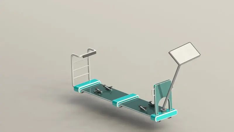
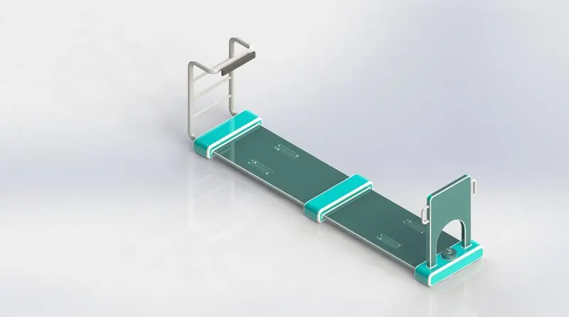
its a movable wheel vehicle for easy transportation on a kiosk diaplay but we are use this vehicle for another purposes too.
we can handle this vehicle through the display panel where we have to only give the command and its automaticaly moving forward, backward or even if you have to down up from the kiosk display its also going up with the support of the supportes where the supporter are mounted. Its easy to access and its very comfortable to use and i make the diplay like moving display means if you have a problem to seeing whats in the fornt you can also rotate right or left the control panel.
i"ve attach all the files of this model in the given link below
https://drive.google.com/file/d/1Zo7gvziHgs6QozjmLOACGZHFfI7fQ4pA/view?usp=share_link
ive also share my another small work of girnder mchine.
https://drive.google.com/file/d/19Yc-bNorG9aTfxja-E8U8bQn6ixIzlQZ/view?usp=share_link
My internship projects where i am working 3 months of my hard works.