Gearbox Sloshing effect
Aim: To simulate the Gearbox sloshing effect in Ansys Fluent by varying the lubricating fluid and immersion levels.
Introduction and Theory (Part 2):
Fluid Sloshing Effect:
In fluid dynamics, slosh refers to the movement of liquid inside another object (which is, typically, also undergoing motion).
Strictly speaking, the liquid must have a free surface to constitute a slosh dynamics problem, where the dynamics of the liquid can interact with the container to alter the system dynamics significantly. Important examples include propellant slosh in spacecraft tanks and rockets (especially upper stages), and the free surface effect (cargo slosh) in ships and trucks transporting liquids (for example oil and gasoline). However, it has become common to refer to liquid motion in a completely filled tank, i.e. without a free surface, as "fuel slosh".
Such motion is characterized by "inertial waves" and can be an important effect in spinning spacecraft dynamics. Extensive mathematical and empirical relationships have been derived to describe liquid slosh. These types of analyses are typically undertaken using computational fluid dynamics and finite element methods to solve the fluid-structure interaction problem, especially if the solid container is flexible. Relevant fluid dynamics non-dimensional parameters include the Bond number, the Weber number, and the Reynolds number.
Sloshing is not a desirable phenomenon. For Example in a road tank vehicle, the directional dynamics and safety performance is adversely affected. Hydrodynamic forces and moments arising from liquid cargo oscillations in the tank understeering or braking maneuvers reduce the stability and controllability of partially-filled tank vehicles.
Anti-slosh devices such as baffles are widely used in order to limit the adverse liquid slosh effect on directional performance and stability of the tank vehicles. Since most of the time, tankers are carrying dangerous liquid contents such as ammonia, gasoline, and fuel oils; therefore stability of partially-filled liquid cargo vehicles is very important. Optimizations and sloshing reduction techniques in fuel tanks such as elliptical tank, rectangular, modified oval, and generic tank shape have been performed in different filling levels using numerical, analytical, and analogical analyses.
Dynamic Meshing:
The dynamic mesh model allows you to move the boundaries of a cell zone relative to other boundaries of the zone, and to adjust the mesh accordingly. The boundaries can move rigidly with respect to each other(linear or rotation motion), and/or deform.
Eg- The motion of the boundaries can be rigid, such as pistons moving inside an engine cylinder or a flap deflecting of an aircraft wing, or deforming, such as the elastic wall of a ballon during inflation or a flexible artery wall responding to pressure pulse from the heart. In either case, the nodes that define the cells in the domain must be updated as a function of time, and hence the dynamic mesh solutions are inherently unsteady.
User Defined Function(UDF):
User-defined functions are programs that can be dynamically loaded with Ansys Fluent to enhance the standard features of the code. For example, you can use a UDF to define your own boundary conditions, material properties, and source terms for your flow regimes, as well as specify customized model parameters, initialize a solution, or enhance post-processing.
Common errors:
Dynamic mesh failed error can occur when the displacement of the mesh in one time step is significant resulting in collapse of the cells, which maybe caused due to excessive skewness of the remeshed mesh. It also leads to negative cell volume detected error, which means the new mesh cell volume is falling below permissible limits. To rectify this issue, the remeshing parameters of the dynamic mesh should be updated according to the mesh scale Info. Also, running Ansys Fluent on one processor in series mode solves the problem sometimes.
One more common error is Floating Point Exception error, which is thrown by the compiler when the equation being solved is producing no solution or there is a mathematical error. To rectify this, we can try mesh refinement, reducing time step size, providing under-relaxation values to pressure and momentum in solution controls, and using first order schemes in spatial discretization. .
Applications: Designing tank vehicles such as ships and trucks transporting fuel.
Modeling Approach:
We need to open Ansys Workbench using Visual Basic C++ command prompt since we will be using a UDF (User Defined Function) which is written in C language and needs to be compiled.
Pre-Processing:
Step 1: Importing geometry
The gearbox design was imported into SpaceClaim.
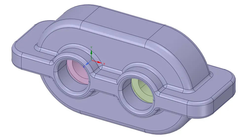
Fig 1. Gearbox design with casing
For the purposes of our simulation, the fluid volume was extracted. Further, the gearbox was cut into half across a plane which divides the gearbox into two halves symmetrically. The following picture depicts the design obtained after this process:
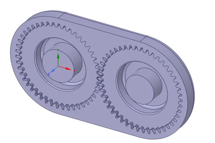
Fig 2. Fluid Imprint of the gears
To further simplify the design, the fluid part of the design was copied and pasted into a new SpaceClaim design. The final design ready for simulation is depicted below: 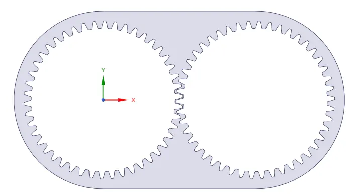
Fig 3. 2D Gear geometry
Step 2: Meshing
The following named selections were created:
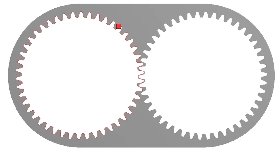
Fig 4. Left gear
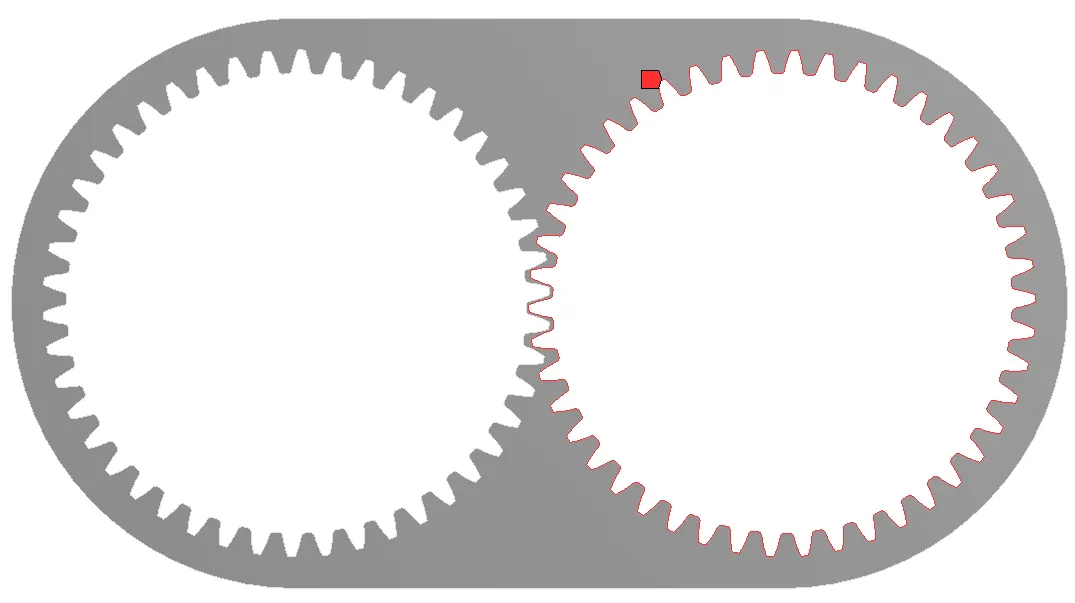
Fig 5. Right gear
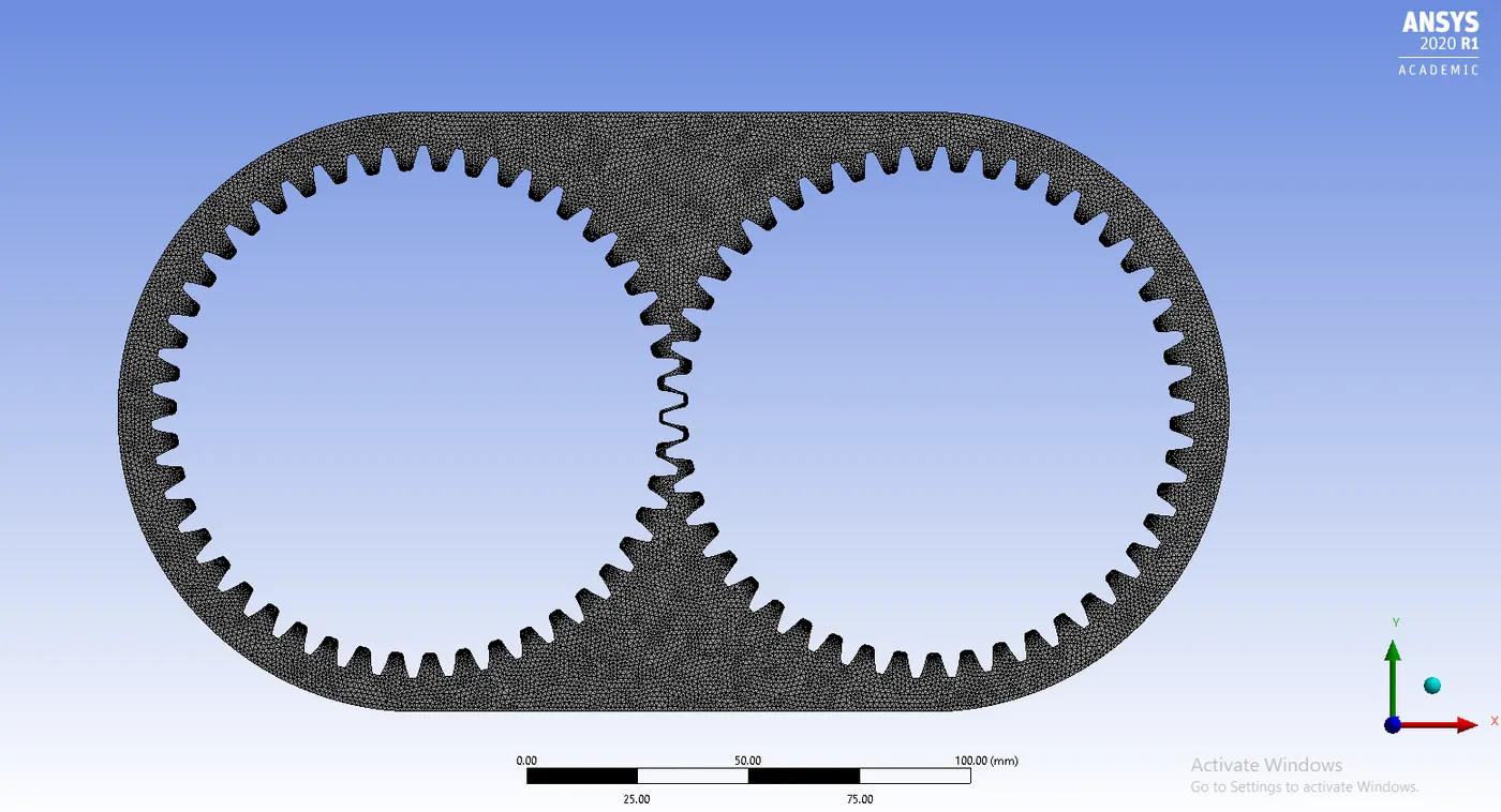
Fig 6. Mesh
Mesh Properties:
Global Element size = 1mm
Method: All triangles
Capture Proximity turned ON.
Number of cells across gap = 1
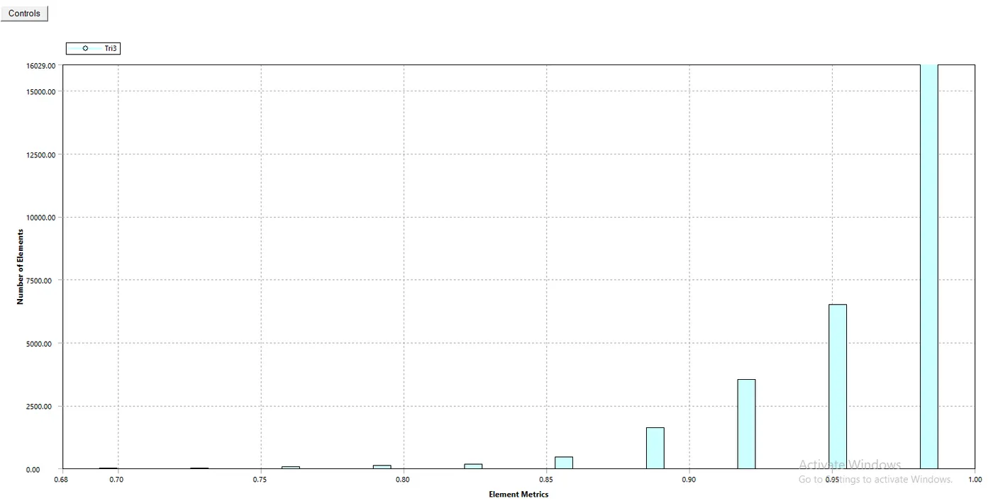
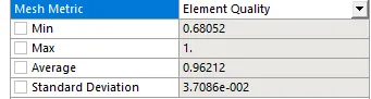
Statistics:

Mesh Properties:
1. Element Quality
2. Aspect Ratio
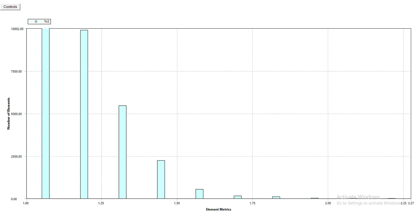
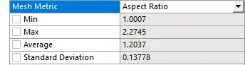
3. Skewness
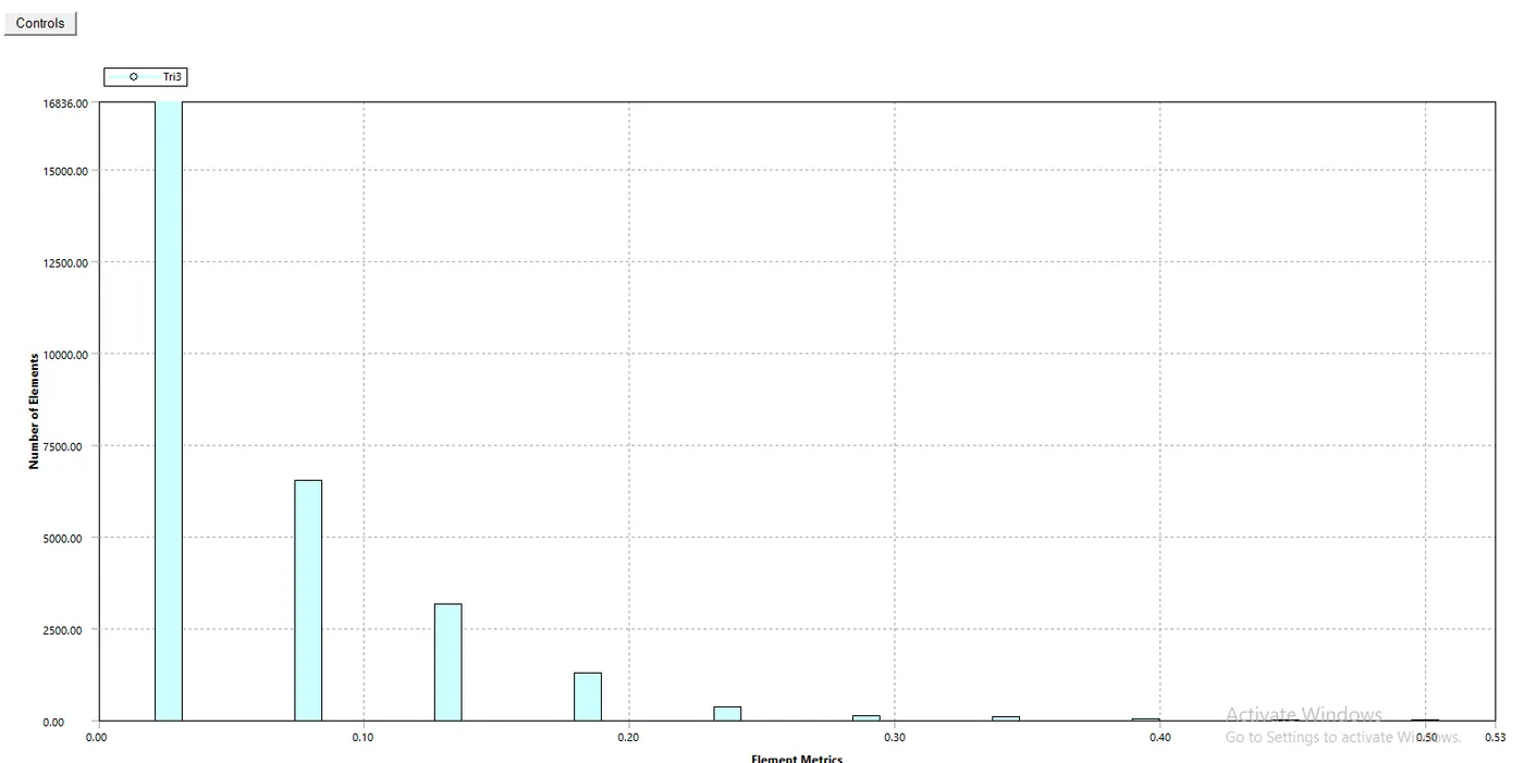
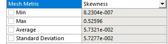
4.Orthogonal Quality
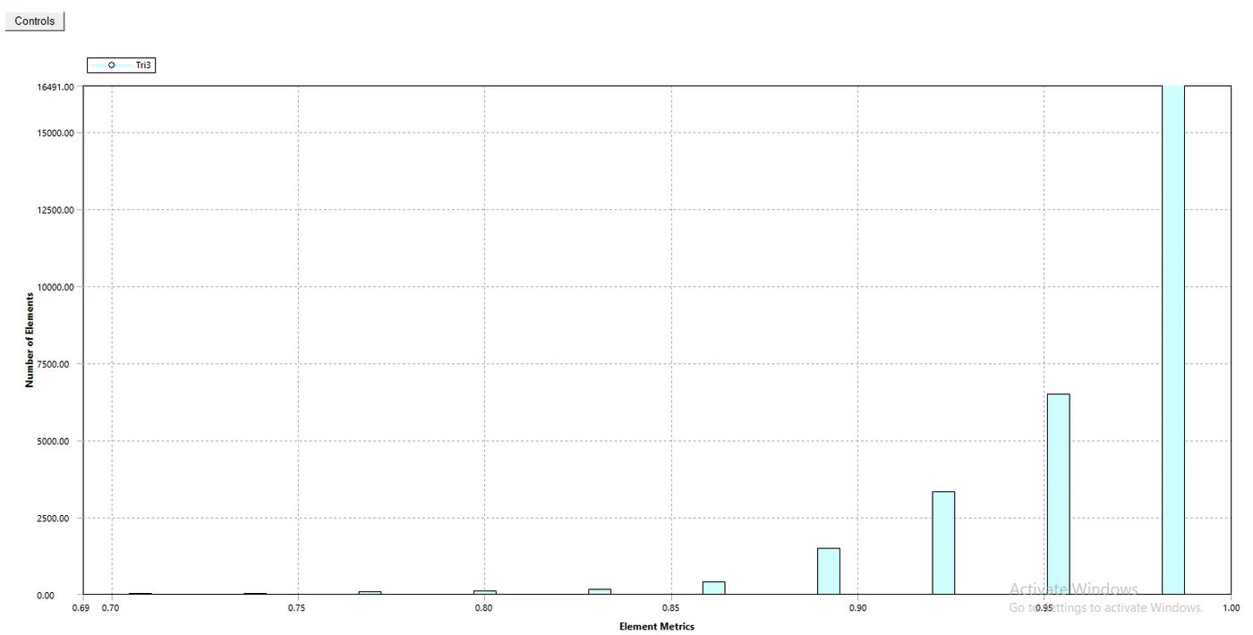
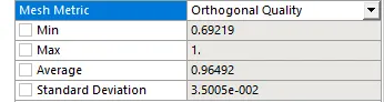
Step 3: Solving using Ansys Fluent
Solver: Pressure based, transient solver with Absolute velocity formulation with Gravity of value -9.81 ms2ms2enabled in the y-axis.
Viscous model: Realizable k-epsilon model with Enhanced Wall Treatment.
Multiphase model: Volume of fluid model with Implicit formulation.
Material properties of air, engine oil, n-heptane:
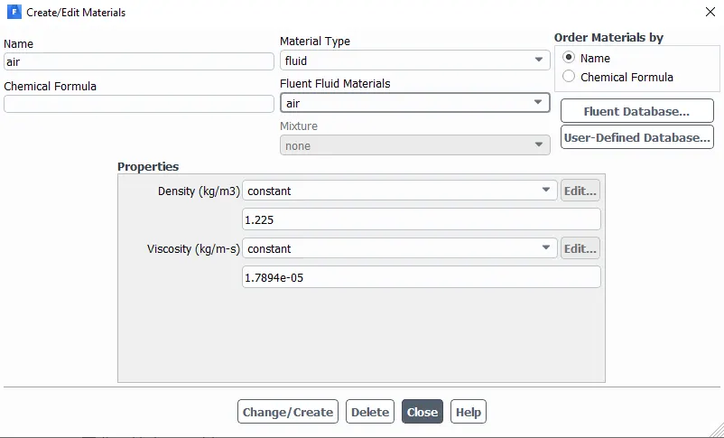
Fig 7. Air properties
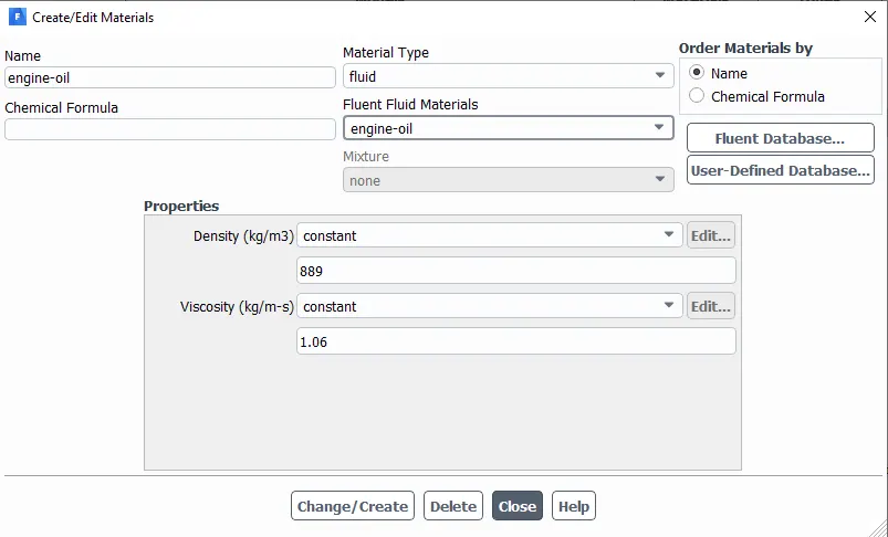
Fig 8. Engine oil properties
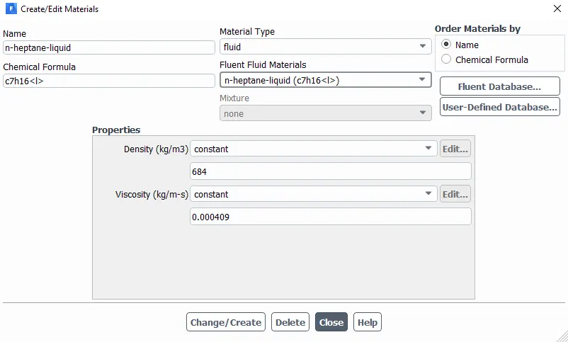
Fig 9. n-heptane liquid properties
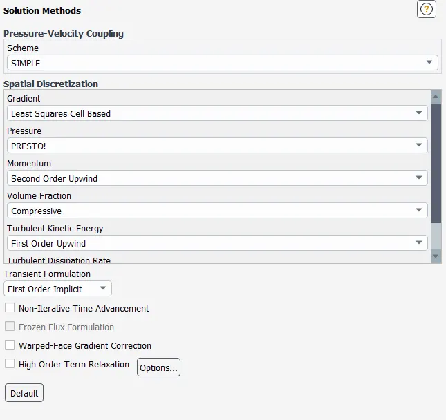
Solution methods:
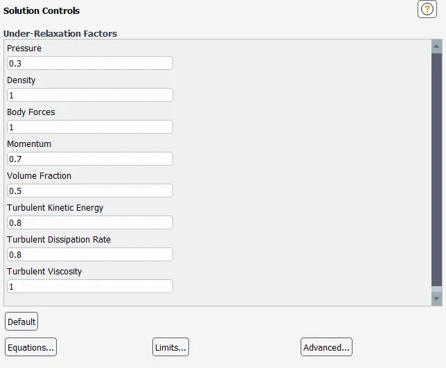
Solution controls:
UDF Function:
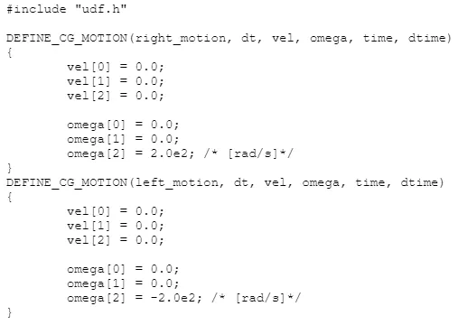
In the above UDF two functions are defined , each associated with the motion of gears. The first function defines the motion of the right gear taking the CG(Center of Gravity) as the input. Similarly, the second function defines the motion of the left gear taking CG as the input. Both the gears are provided with an angular velocity of 200 rad/s, with the sign indicating the direction of rotation.
A dynamic mesh is created for this purpose with re-meshing parameters taken from mesh scale info.
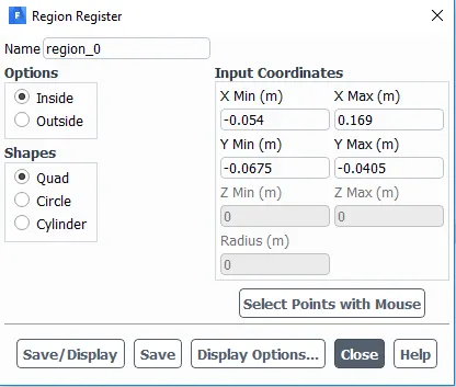
The regions where the fluid(engine oil or n-heptane) resides has to be marked for refinement. This is done by providing x_max, x_min, y_max, y_min values.
For the case of 20% immersion:
For the case of 30% immersion:
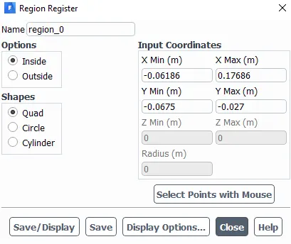
Total height of enclosure = 135 mm
20 % of Gear box enclosure = 0.2*135 = 27 mm (from base)
30 % of Gear box enclosure = 0.3*135 = 40.5 mm (from base)
No. of time-steps:
The angular velocity, ω = 200 rad/s,
we can calculate number of revolution per minute from the formula, ω=2⋅π⋅N60ω=2⋅π⋅N60
from which we get N = 1911 rpm = 31.84 rotations/second
Using this time for one complete rotaion is 0.031 second.
Due to processing limits, the simulation was conducted for only 2 complete revolutions, simulation time = 2*0.031 = 0.062 second.
The number of time steps taken to complete this is 620(simulation time/time step size).
The simulation was conducted for around 700 time steps.
Results:
1. Gearbox Animation
Case 1: 20% Immersion, Fluid - Engine oil.
Case 2: 30% Immersion, Fluid- Engine oil.
Case 3: 20% Immersion,Fluid-n-heptane (c7h16).
Case 4: 30% Immersion,Fluid-n-heptane (c7h16).
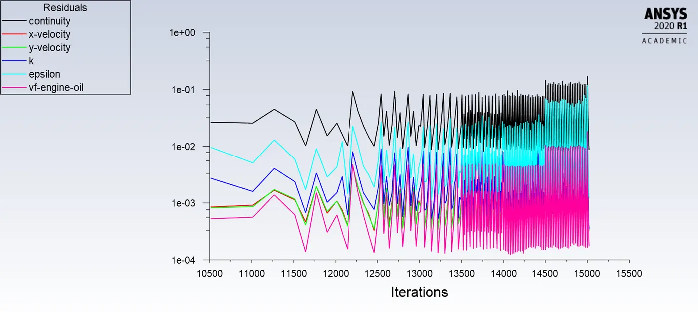
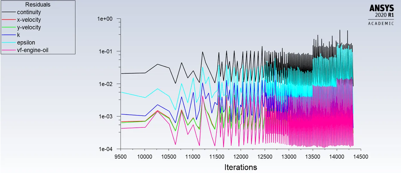
2. Residuals
Case1:
Case2:
Case3:
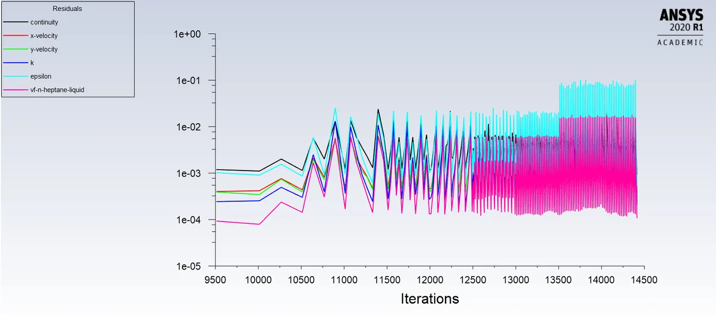
Case4:
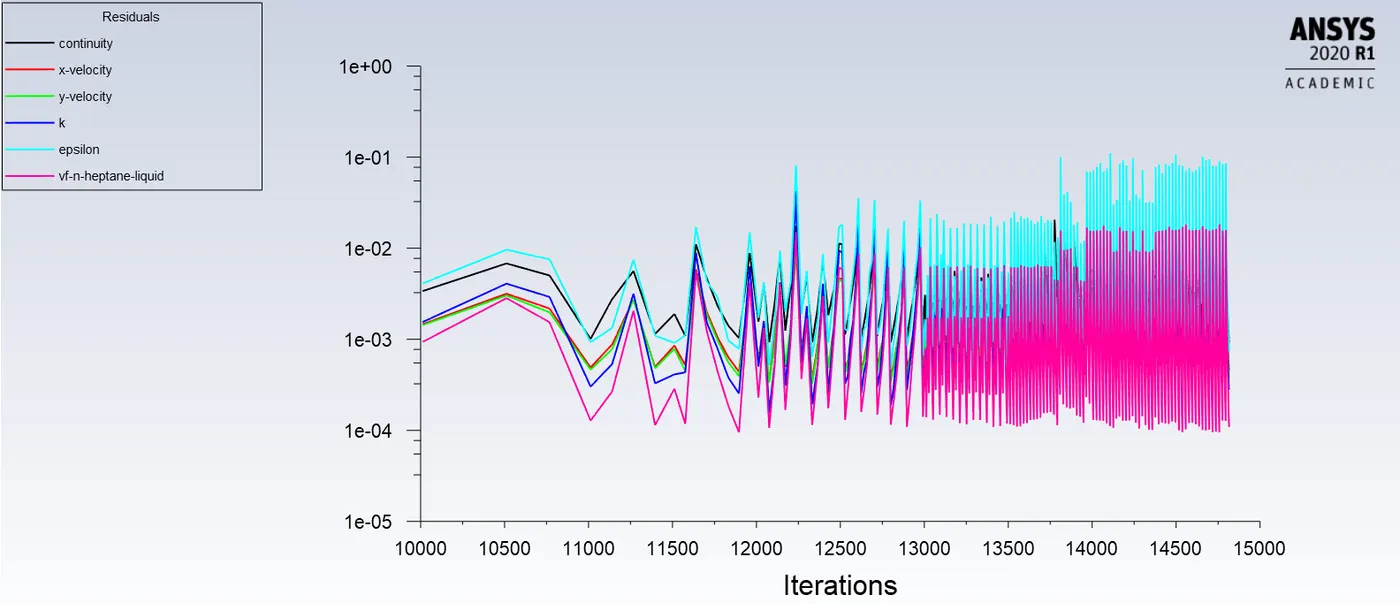
From the residuals , we can conclude the solution is converged even though its not falling because, the peak and valleys are repeating producing periodic results.
Conclusion:
1. 30% immersion of engine-oil and n-heptane is useful because of higher lubrication at all teeths due to greater immersion.
2. 30% immersion of n-heptane liquid has a higher sloshing effect due to greater immersion and less viscosity.
3. 30% immersion of engine oil is the best combination due to higher lubrication at all the teeth and higher viscosity.
4. Sloshing effect is high in n-heptane liquid due to lower viscosity.
5. 20% immersion of engine oil shows the least sloshing effect due to lower immersion and higher viscosity.
Hence, while designing a gearbox system we should keep the immersion levels and viscosity of the fluid in mind , to keep the sloshing effect in control, at the same time producing greater lubrication.