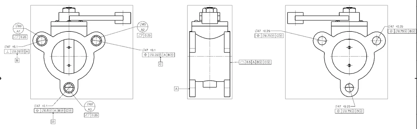
GD&T applied on the assembly of a butterfly valve.
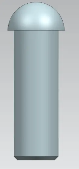
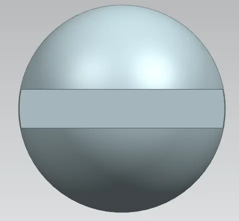
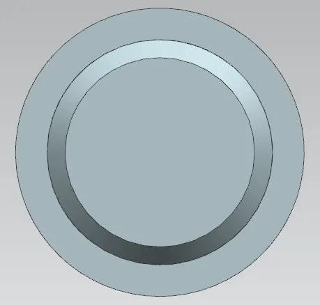
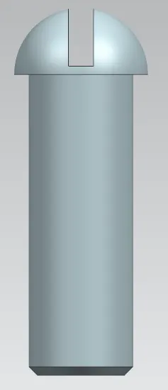
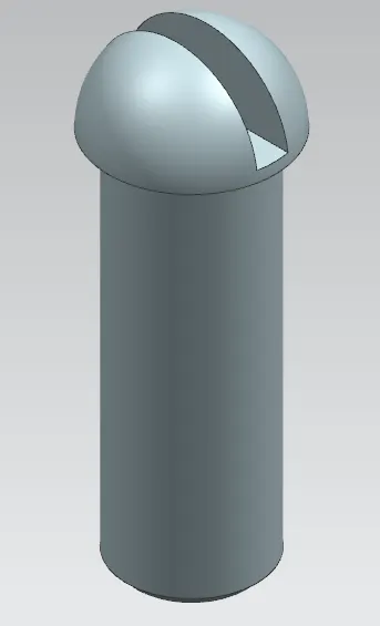
Screw 1 (To connect the disc and shaft)
Following are the images of the screw;
Front and back view
Top view
Bottom view
Right and left side view
Isometric view
Below is the link of the file containing modelled part;
https://drive.google.com/file/d/1EBDN-Y63TsVxu1ujtqHdYykBa88ta9gy/view?usp=sharing
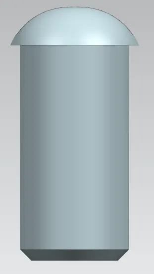
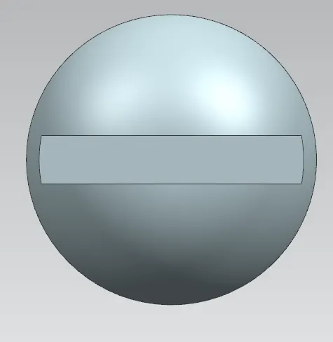
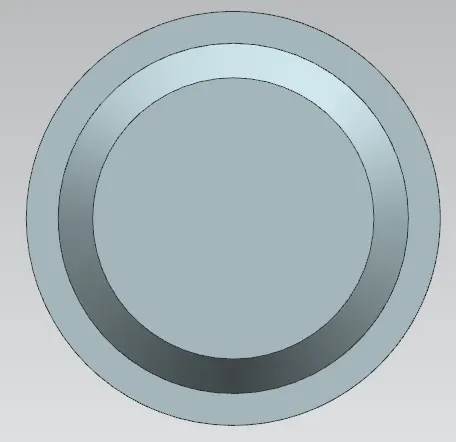
Screw 2 (To connect the retainer and lever)
Following are the images of the screw;
Front and back view
Top view
Bottom view
Right and left side view
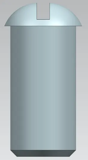
Below is the link of the file containing modelled part;
https://drive.google.com/file/d/1xWcTiPxheQyDezs5Nal_0YS4adC9hCQv/view?usp=sharing
Butterfly Valve
Following are the images of the butterfly valve assembly;
Front view
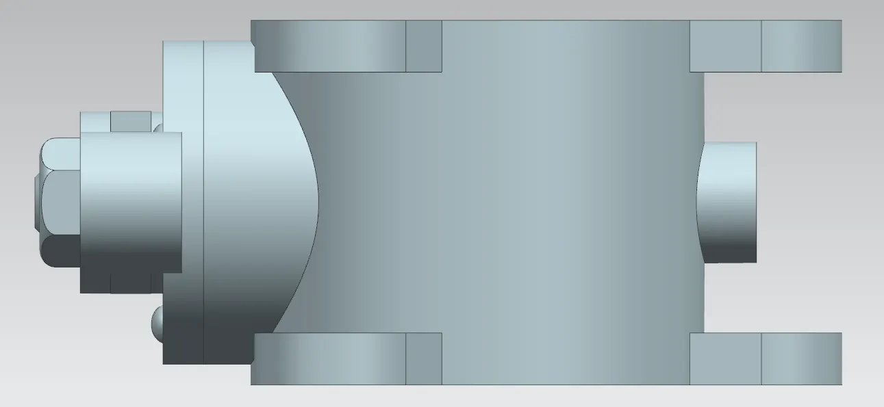
Top view
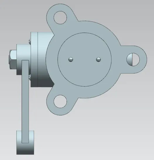
Bottom view
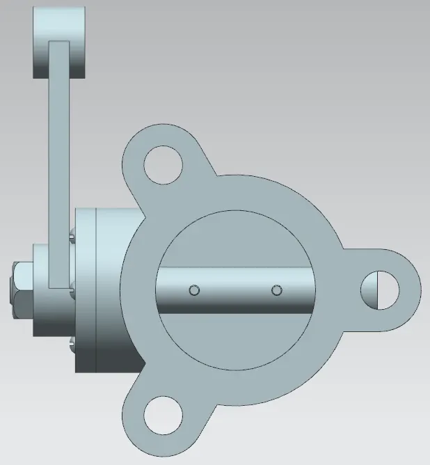
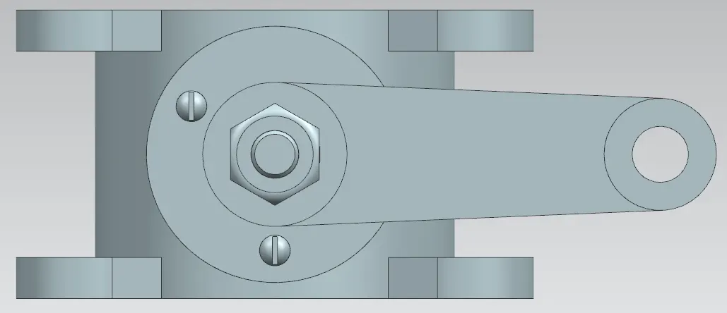
Right side view
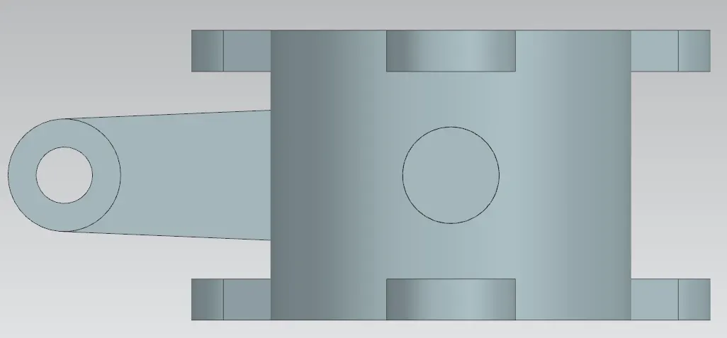
Left side view
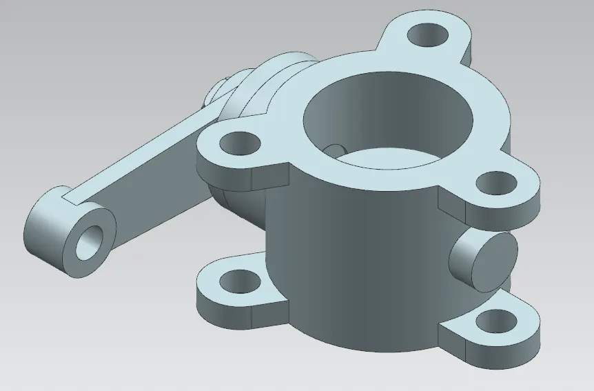
Isometric view
Following are the images of the drawing of assembly;
Full sheet drawing with GD&T
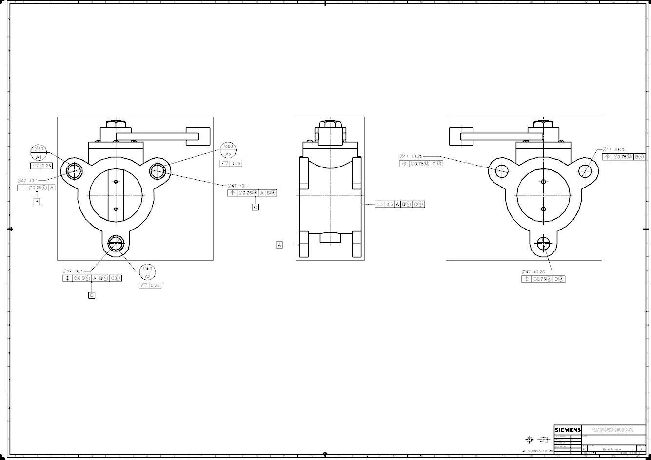
Drawing sheet close-up
Below is the link of the zip file containing all the parts and assembly;
https://drive.google.com/file/d/1pmalwiipT7HRC3-y4NAkVymYEPEdF-g2/view?usp=sharing