Gate Valve Parametric Study
Aim: To conduct a parametric study on gate valve simulation by varying the opening of the gate disc.
Introduction and Theory: Gate valves work by inserting a rectangular gate or wedge into the path of a moving fluid. They are operated by a threaded stem which connects the actuator (generally a hand wheel or a motor) to the stem of the gate. If the valve has a rising stem its position can be seen just by looking at the position of the stem. A gate valve is used to control the fluid flow through lifting and descending the gate. A gate distinct feature is to provide an unobstructed passageway, which includes minimal pressure loss over the valve.
When the gate is fully opened there is no restriction to the flow hence the pressure drop is low comparatively. Generally, the gate valve is fully closed or fully open as a partially opened valve may experience vibration which may lead to excessive wear. A gate valve's main component is a body, seat, stem, bonnet, and actuator. The primary mechanism is straight forward where the handwheel is rotated to move the gate up and down via threads. They require more than a 360-degree turn to fully open the valve.
Flow-coefficient (`C_v`):
The flow coefficient of a device is a relative measure of its efficiency at allowing fluid to flow. It describes the relationship between the pressure drop across an orifice valve or other assembly and the corresponding flow rate.
Mathematically, the flow coefficient `C_v` (or flow-capacity rating of the valve) can be expressed as:
`C_v = Qsqrt((SG)/(Delta P))`
Where,
Q is the flow rate (expressed in US gallons per minute)
SG is the specific gravity of the fluid(for water =1)
`Delta P` is the pressure drop across the valve measured in psi`
Flow-factor (`k_v`):
The metric equivalent flow factor is calculated using metric units.
`K_v = Qsqrt((SG)/(Delta P))`
Where,
Q is the flow rate(expressed in `m^3/(hr)`)
SG is the specific gravity of the fluid(for water =1)
`Delta P` is the pressure drop across the valve measure in KPa`
`k_v` can be calculated from `C_v` using the equation:
`K_v = 0.865 C_v`
Applications: Gate valves are used in a variety of industries such as oil and gas, manufacturing, pharmaceuticals and are suitable for both aboveground and underground applications. They are suitable for most fluids including steam, water, oil, and gas.
Modeling Approach:
Pre-Processing:
1. Importing geometry in SpaceClaim
The following geometry was imported into SpaceClaim.
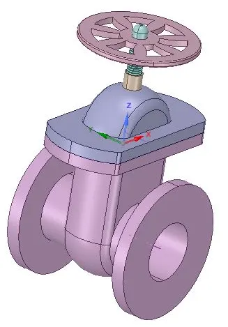
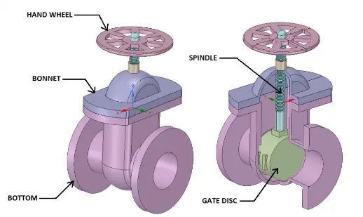
It has the following components.
First, we pull the inlet and outlet regions of the pipe to 800 mm on both sides.
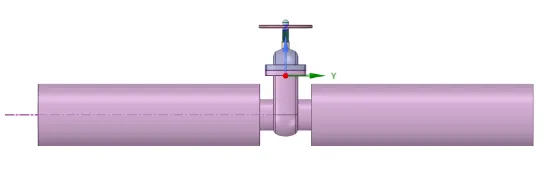
To simulate the effect of the gate disc on the mass flow rate of the fluid at the outlet, the gate disc is lifted by 10mm in the +ve Z direction so that the flow path is partially open. This is parameterized. Next, the fluid is extracted from the solid geometry.
The parameterization process helps us change the gate disc height values and compute the required output parameters without having to repeat the same process again. The remaining solid geometries are suppressed.
Extracted fluid geometry is shown below:
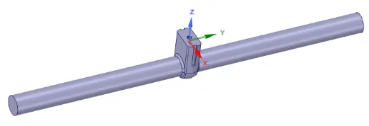
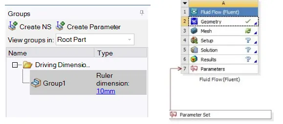
After the parameterization process, a group and parameter tree is created:
2. Meshing
The following mesh was created.
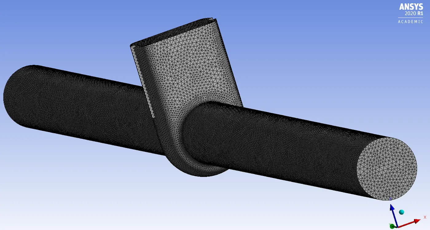
Element size: 5.5mm
Named Selections: Inlet and Outlet
Statistics:

Mesh Quality:
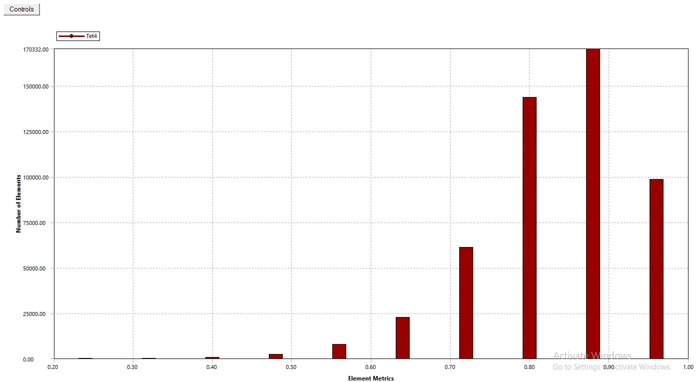
1. Element Quality

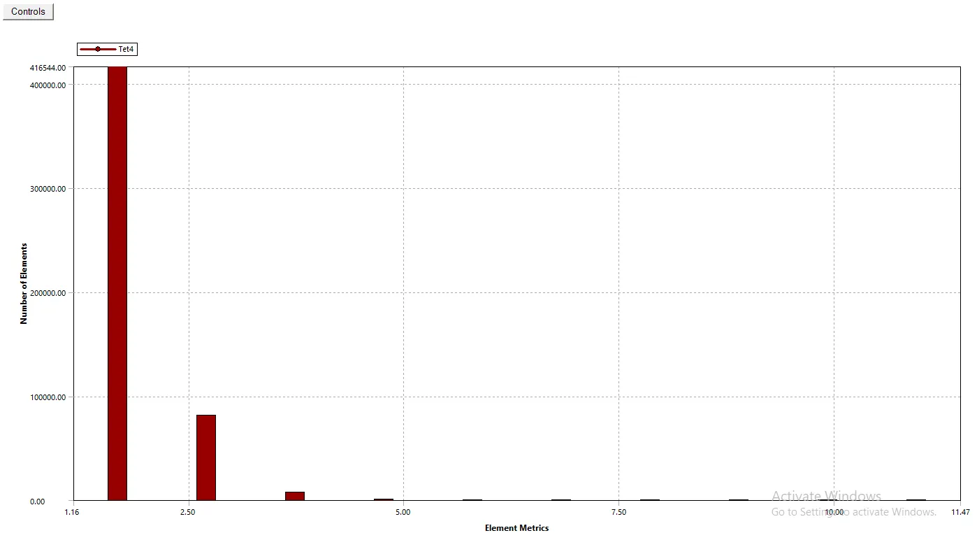
2. Aspect Ratio

3. Skewness
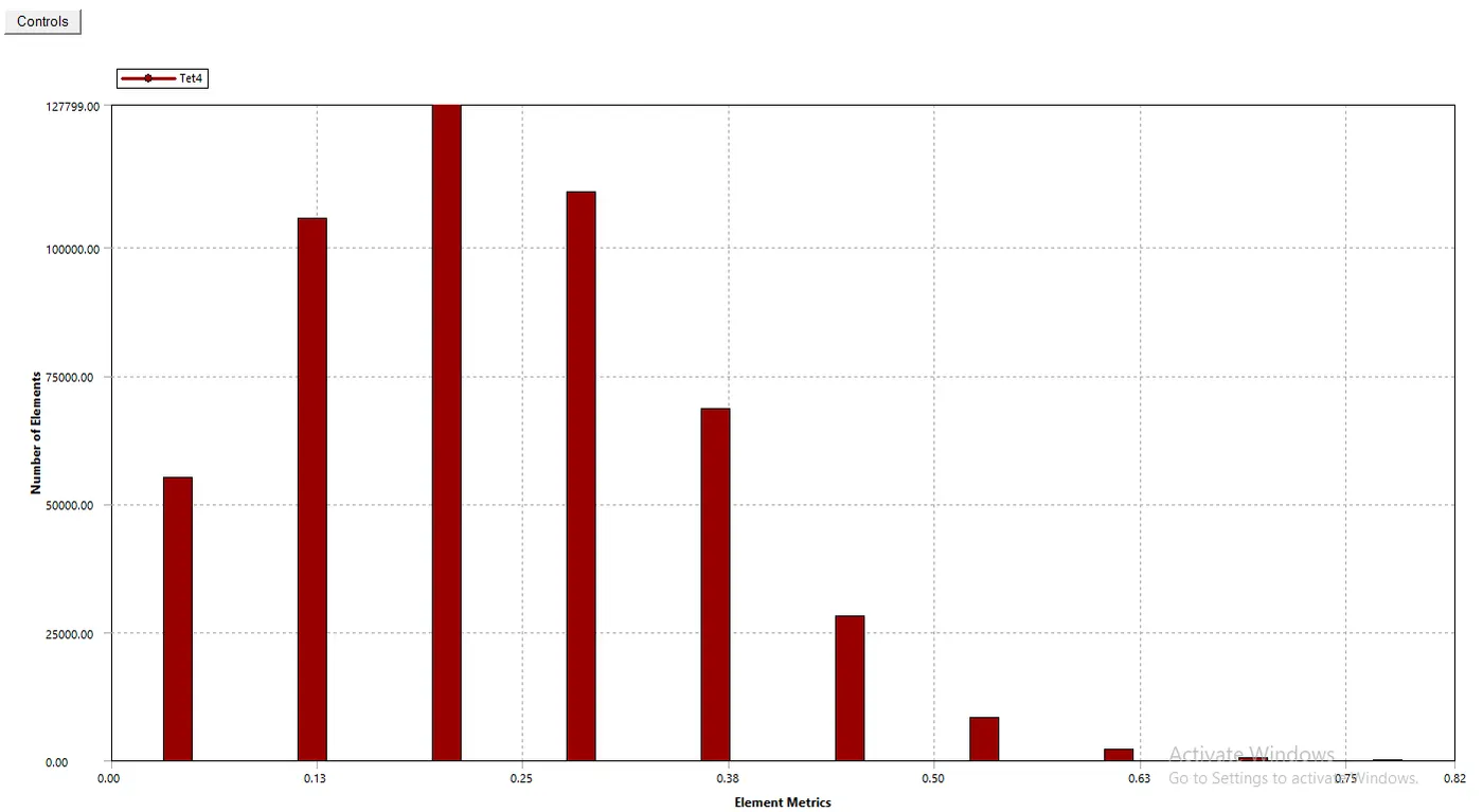

4. Orthogonal Quality
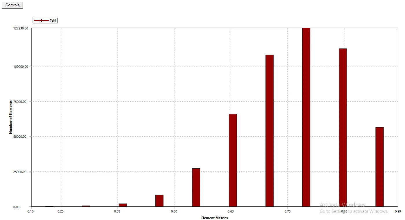

Step 3: Solving using Fluent:
Steady-state, pressure-based solver with gravity enabled of value 9.81 m/s^2 in -ve z-direction.
Viscous model: K-epsilon, Realizable with Scalable wall functions.
Material Properties: Water-liquid(H2O), Density:998.2 kg/m^3 , Viscosity:0.001003 kg/(m-s)
Boundary Conditions:
Inlet: Type= Pressure Inlet
Gauge Total Pressure = 10 Pa
Outlet: Type= Pressure Outlet
Gauge Total Pressure = 0 Pa
Wall: No-slip, stationary wall
Interior: Type= Interior
Solution Method:
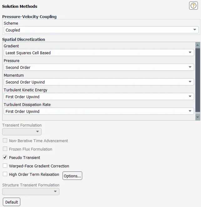
Solution Initialization:
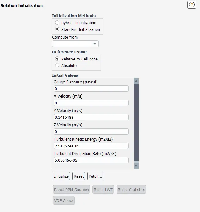
Since we have provided Pressure Inlet condition at the inlet, using Standard Initialization we get the values of velocity at the inlet, from which we can conclude that the flow is turbulent after calculating the Reynolds Number.
We create an output parameter for the mass flow rate at the outlet in the report definition.
Also, 2 planes are generated in the vicinity of the valve ahead and behind respectively, to calculate the area-weighted average pressure, which will be used to calculate flow-factor and flow-coefficient.
The solution is calculated for the 10 percent opening and the further design points(by varying opening of the gate valve) are calculated automatically in the parameterization process. The following results are obtained:
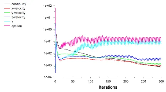
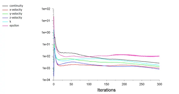
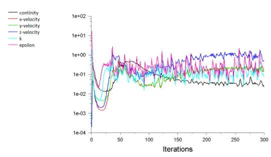
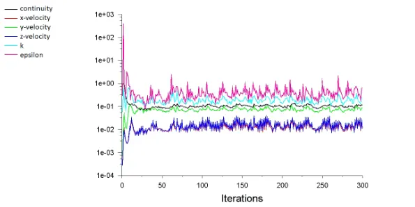
Residuals:
1. 10 mm opening
2. 20 mm opening
3. 30 mm opening
4. 40 mm opening
5. 50 mm opening
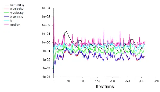
6. 60 mm opening
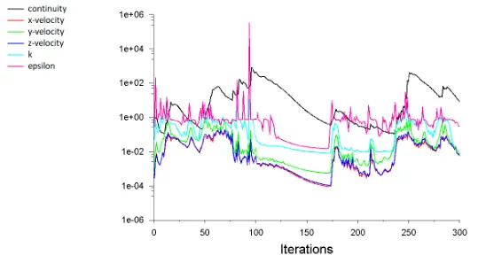
7. 70 mm opening
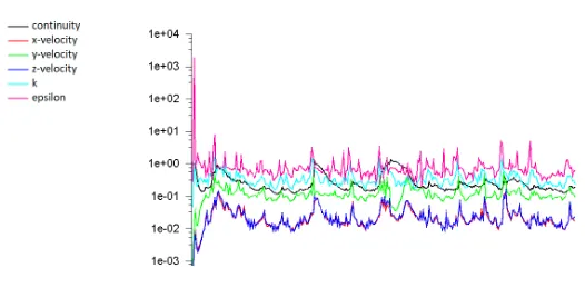
8. 80 mm opening
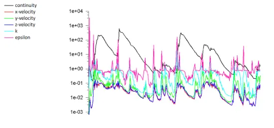
Since the residuals have constant crests and troughs we can say that the solution is converged.
Results:
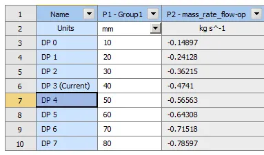
Mass flow rate:
1. 10 mm opening
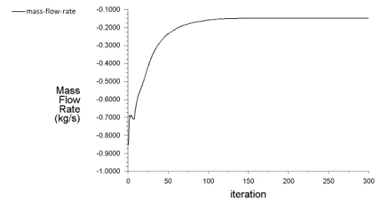
2. 20 mm opening
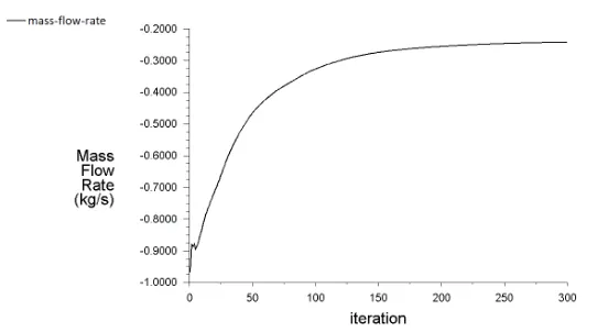
3. 30 mm opening
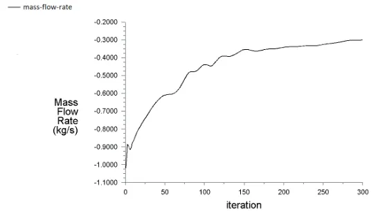
4. 40 mm opening
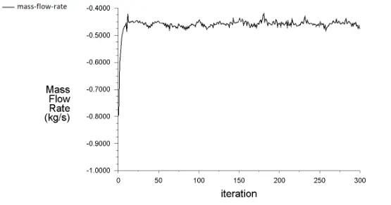
5. 50 mm opening
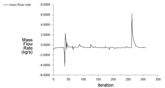
6. 60 mm opening
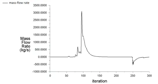
7. 70 mm opening
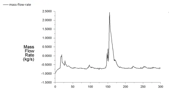
8. 80 mm opening
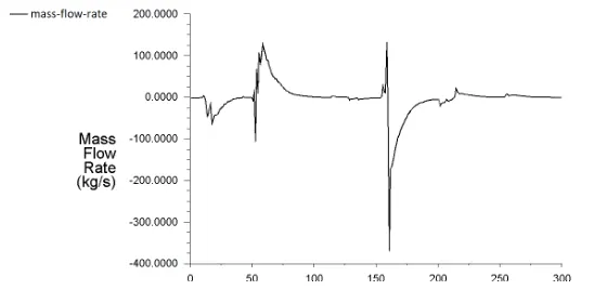
Differential Pressure:
1. 10 mm opening(before valve)
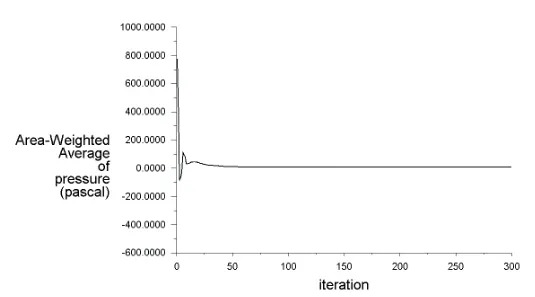
2. 10 mm opening(after valve)
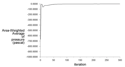
3. 20 mm opening(before valve)
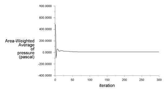
4. 20 mm opening(after valve)
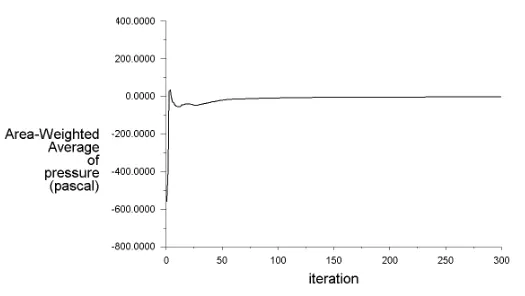
5. 30 mm opening(before valve)
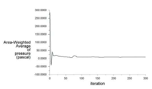
6. 30 mm opening(after valve)
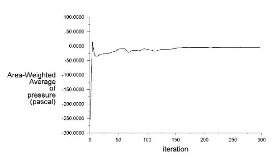
7. 40 mm opening(before valve)
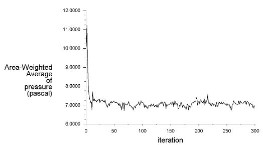
8. 40 mm opening(after valve)
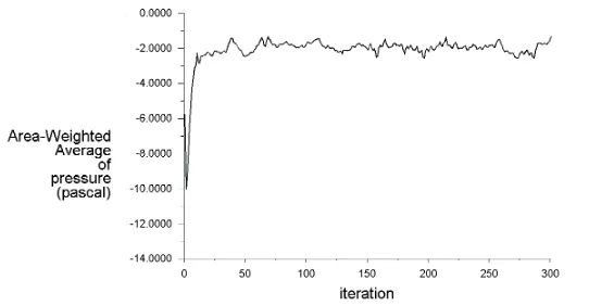
9. 50 mm opening(before valve)
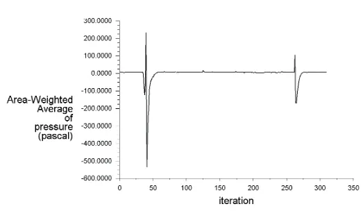
10. 50 mm opening(after valve)
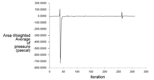
11. 60 mm opening(before valve)
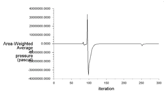
12. 60 mm opening(after valve)
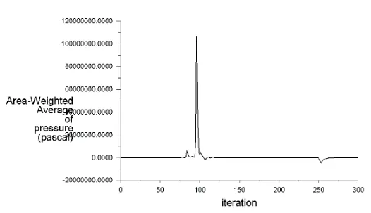
13. 70 mm opening(before valve)
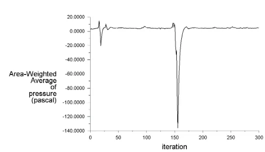
14. 70 mm opening(after valve)
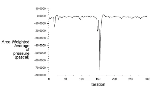
15. 80 mm opening(before valve)
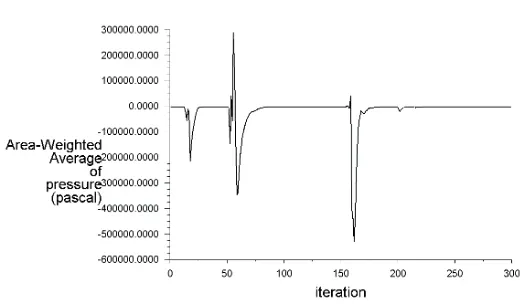
16. 80 mm opening(after valve)
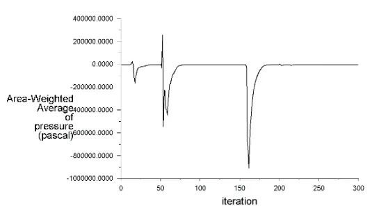
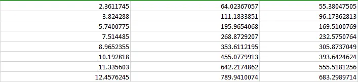
Table:
Gate Lift Pressure Inlet(in Pa) Pressure Outlet(in Pa) Pressure Drop(in Pa) Pressure Drop(in psi) Mass flow rate(in kg/s)

Mass flow rate(in gal/min) Flow Coefficient Flow factor
The graph of flow-coefficient/flow-factor vs opening percentage of gate valve:
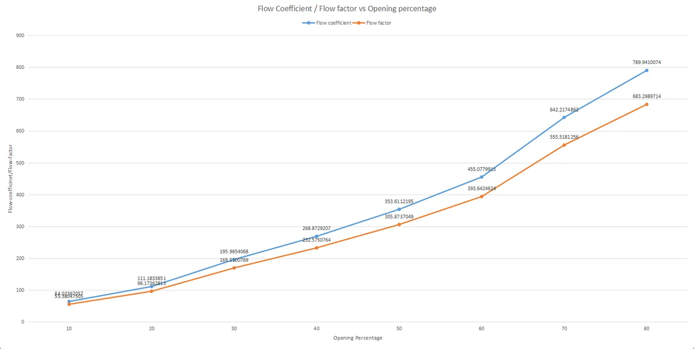
From the above plot, we can say that with increasing gate valve opening, the flow-factor and the flow-coefficient values increases.
Sample Calculation:
For 50% opening:
Pressure before gate valve, P1= 7.6923 Pa
= 7.6923*0.000145038 psi
= 0.0011156 psi
Pressure after gate valve, P2 = 3.2737 Pa
= 3.2737*0.000145038 psi
= 0.0004748109 psi
Mass flow rate,Q = 0.56563 kg/s
= 0.56563 * 15.85 gal/min
= 8.965 gal/min
Differential Pressure `Delta`P = P1-P2
= 0.000640865 psi
Specific Gravity = 0.997(for water)
Flow coefficient,`C_v` = Q*`sqrt((SG)/(Delta P))`
= 353.611 `gal.(min)^-1.lb^-0.5.(Inch)`
Flow factor,`K_v` = 0.865 * `C_v`
= 305.873 `m^3.h^-1.(Bar)^(-0.5)`
Step 4:Post-Processing
1.Pressure Contours:
1.1. 10 mm opening
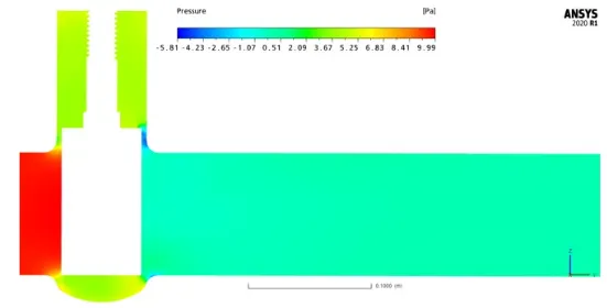
1.2. 20 mm opening
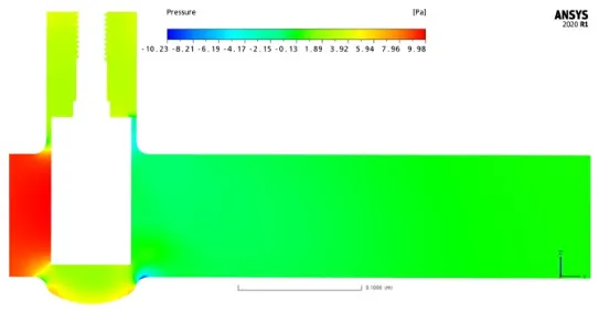
1.3. 30 mm opening
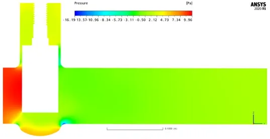
1.4. 40 mm opening
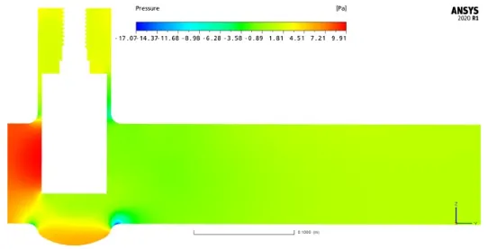
1.5. 50 mm opening
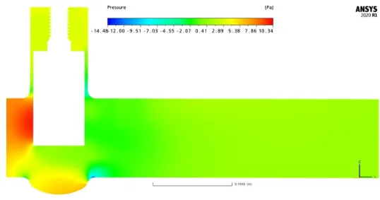
1.6. 60 mm opening
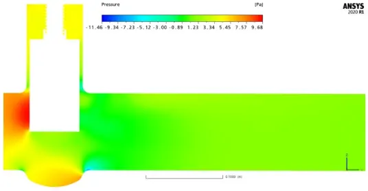
1.7. 70 mm opening
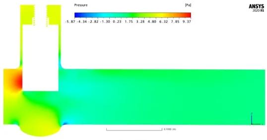
1.8. 80 mm opening
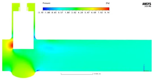
2.Velocity Contours:
2.1. 10 mm opening
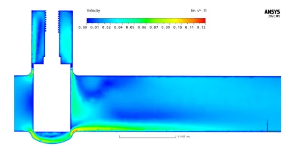
2.2. 20 mm opening
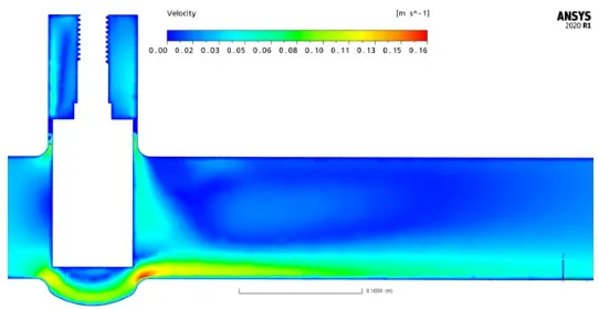
2.3. 30 mm opening
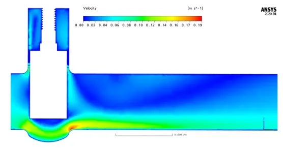
2.4. 40 mm opening
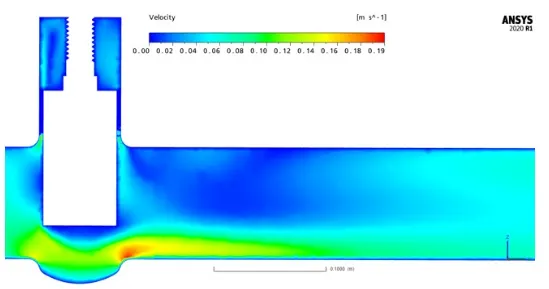
2.5. 50 mm opening
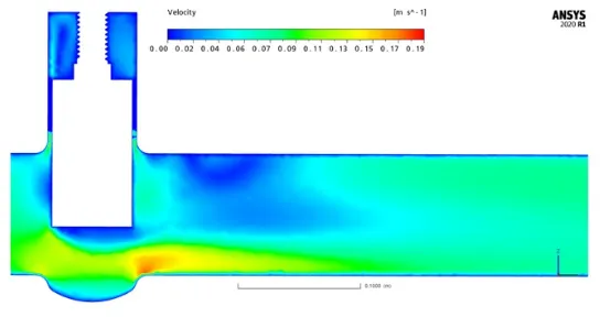
2.6. 60 mm opening
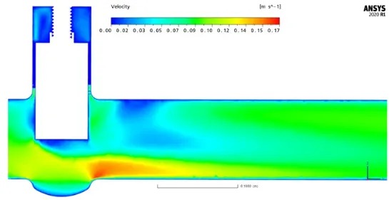
2.7. 70 mm opening
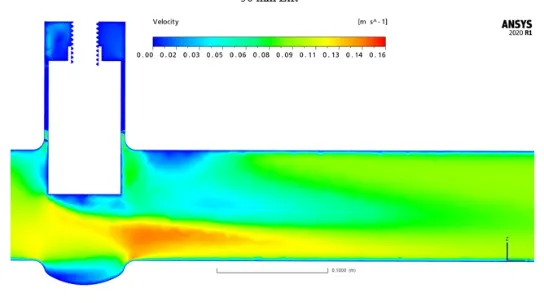
2.8. 80 mm opening
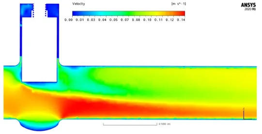
Conclusion:
1. Flow-coefficient and flow-factor increases with increasing opening percentage.
2. Differential pressure across the gate valve decreases with increasing opening percentage. This is because there is less blockage to the flow.
3. Mass-flow rate and velocity increases with increasing opening percentage. This is because there is more pathway for the water to flow.
4. Gate valve should operate in a fully-opened or fully-closed position. A partially-opened valve induces vibration which can damage the gate valve.
5. Also the gate valve should be closed gradually rather than suddenly, as it causes a water hammer effect which can again damage the gate valve.