Gate Valve Parametric Study
Aim: To perform a parametric study on the gate valve simulation by setting the opening from 10 % to 80%.
Introduction:
A gate valve can be defined as a type of valve that used a gate or wedge type disk and the disk moves perpendicular to flow to start or stop the fluid flow in piping.
A gate valve is the most common type of valve used in any process plant. It is a linear motion valve used to start or stop fluid flow. In service, these valves are either in a fully open or fully closed position.
When the gate valve is fully open, the disk of a gate valve is completely removed from the flow. Therefore virtually no resistance to flow. Due to this very little pressure drops when fluid passes through a gate valve.
To achieve proper sealing, when the valve is fully closed, 360° surface contact is required between disk and seats.
Gate valves should not be used for regulation or throttling of flow because accurate control is not possible. The high velocity of the flow in the partially open valve may cause erosion of the disc and seating surfaces and also creates vibration and noise.
Solving & Modelling approach:
Geometry Preparation:
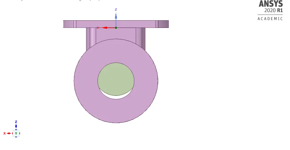
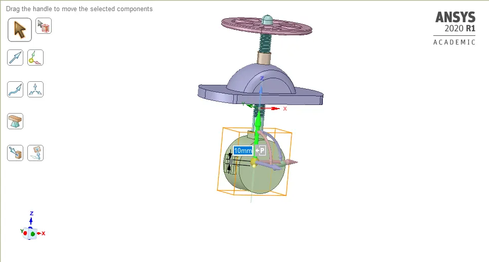
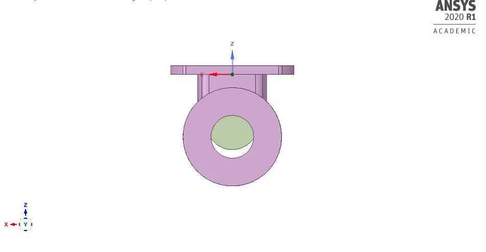
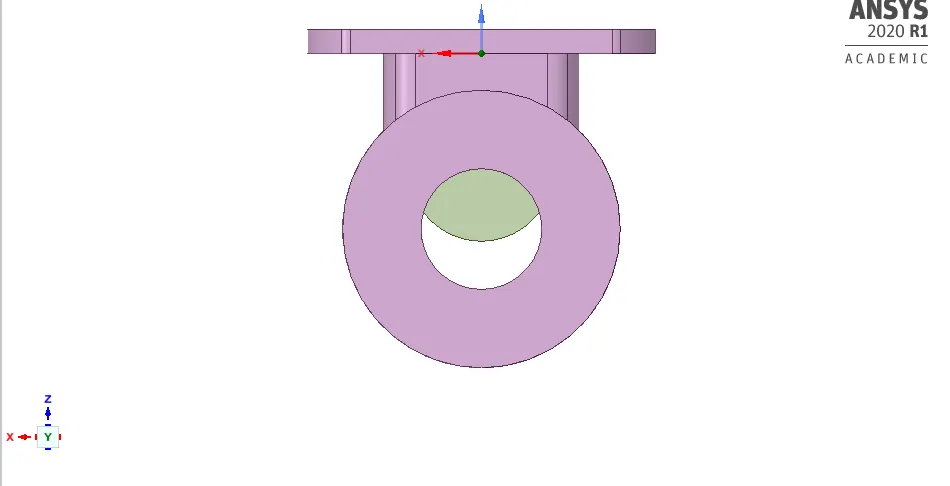
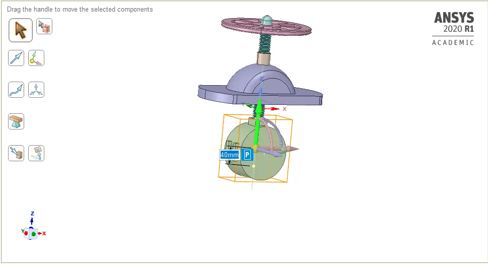
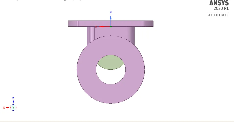
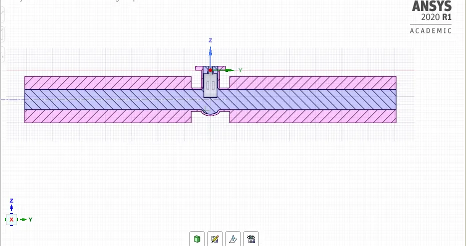
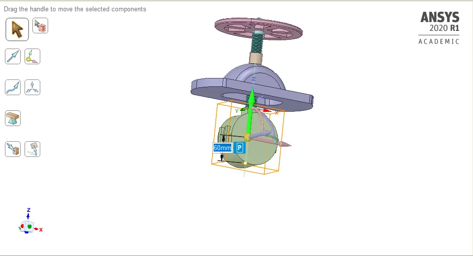
Gate valve model is imported in Spaceclaim.
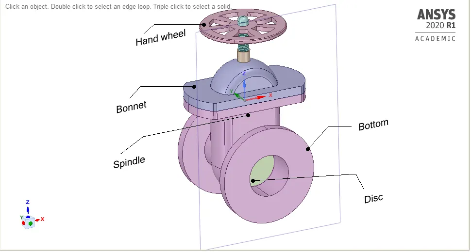
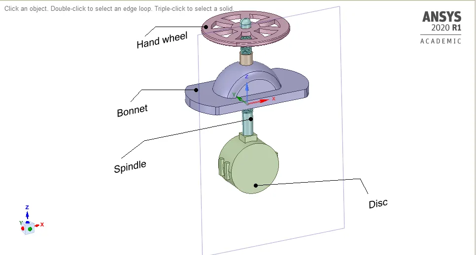
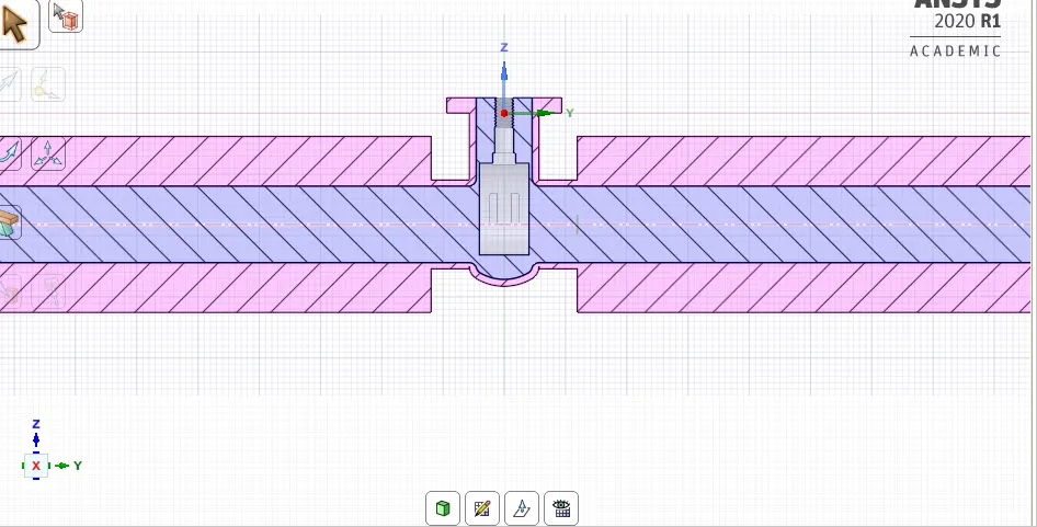
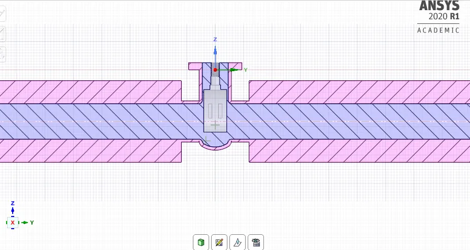
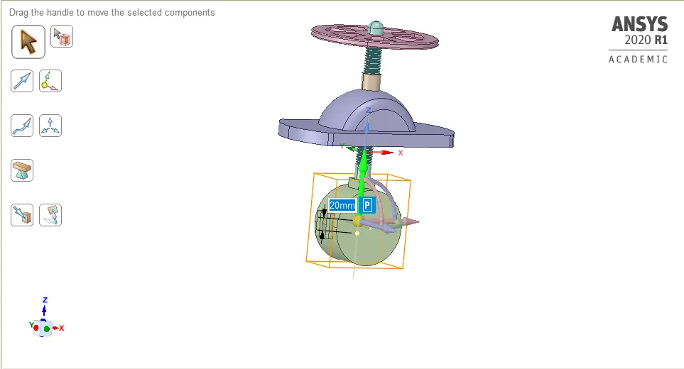
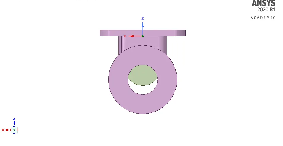
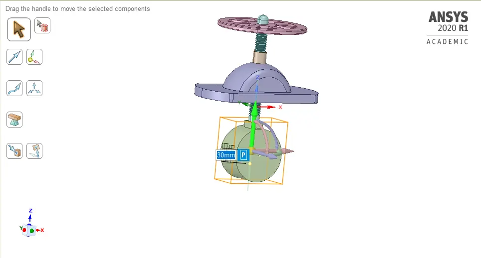
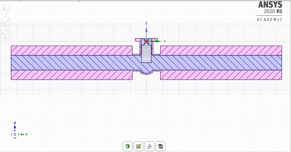
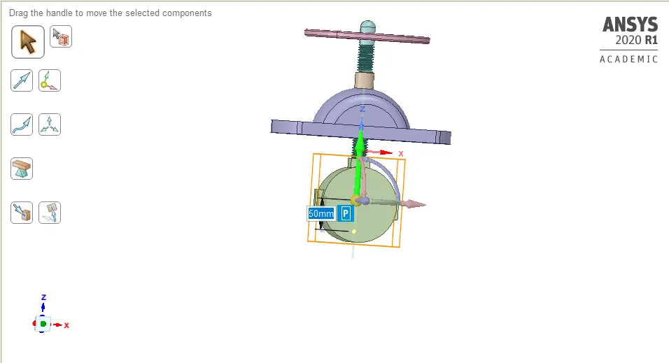
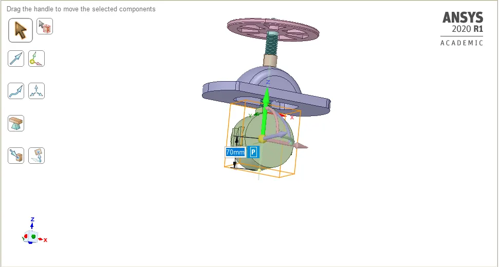
#With the use of Move Tool ,Disc is lifted according to requirement.
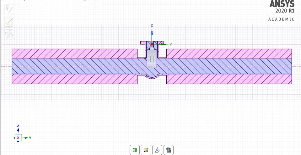
#Volume extracted in Spaceclaim
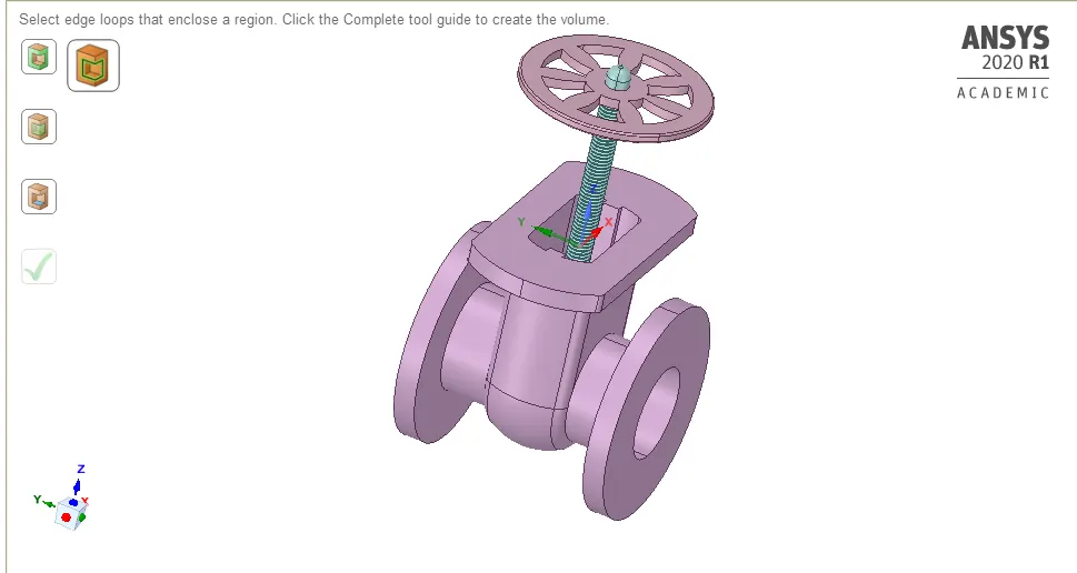
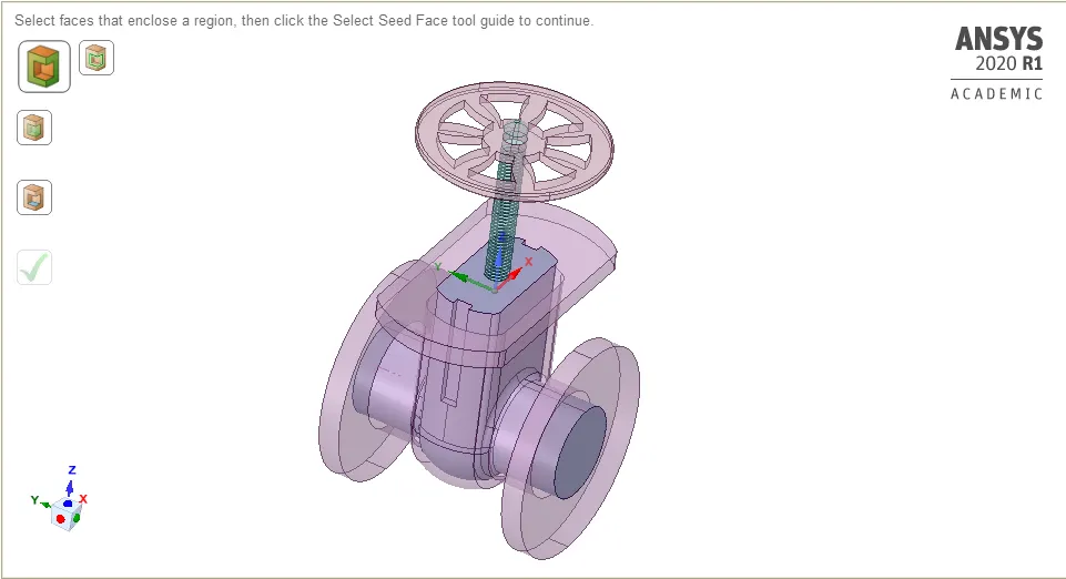
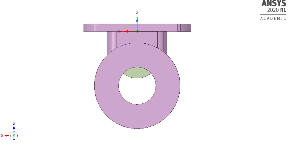
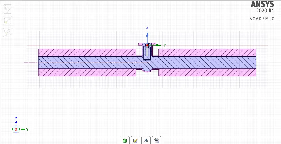
#With the use of Pull Tool ,Face of bottom body is pulled for 800 mm on both sides.
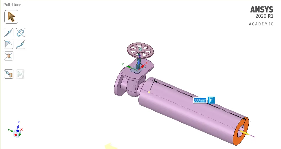
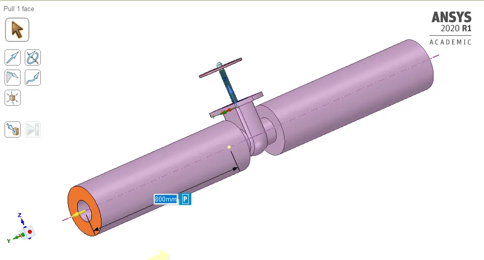
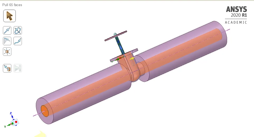
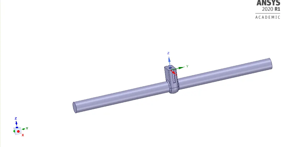
#On fluid volume,right click and select Update volume body in context.To update fluid volume.
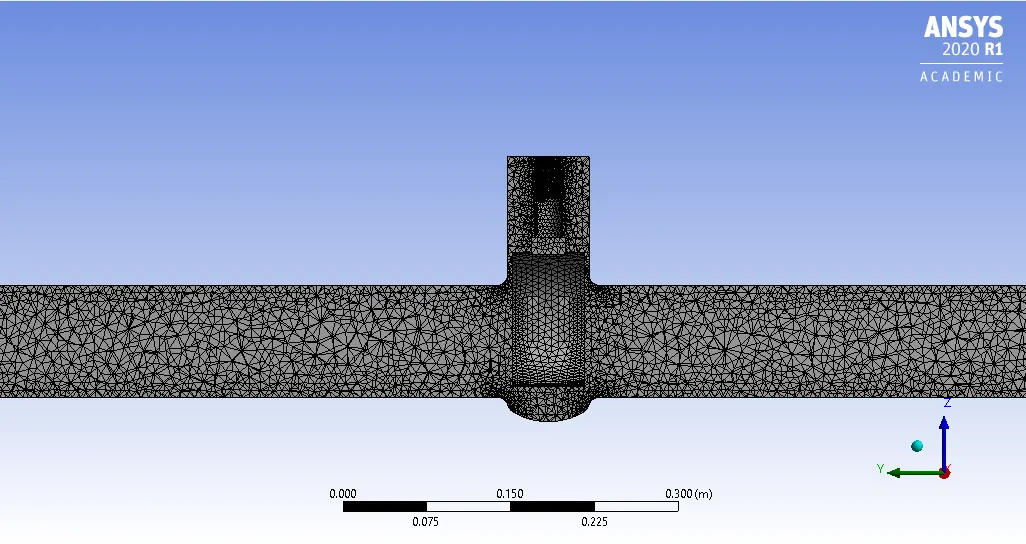
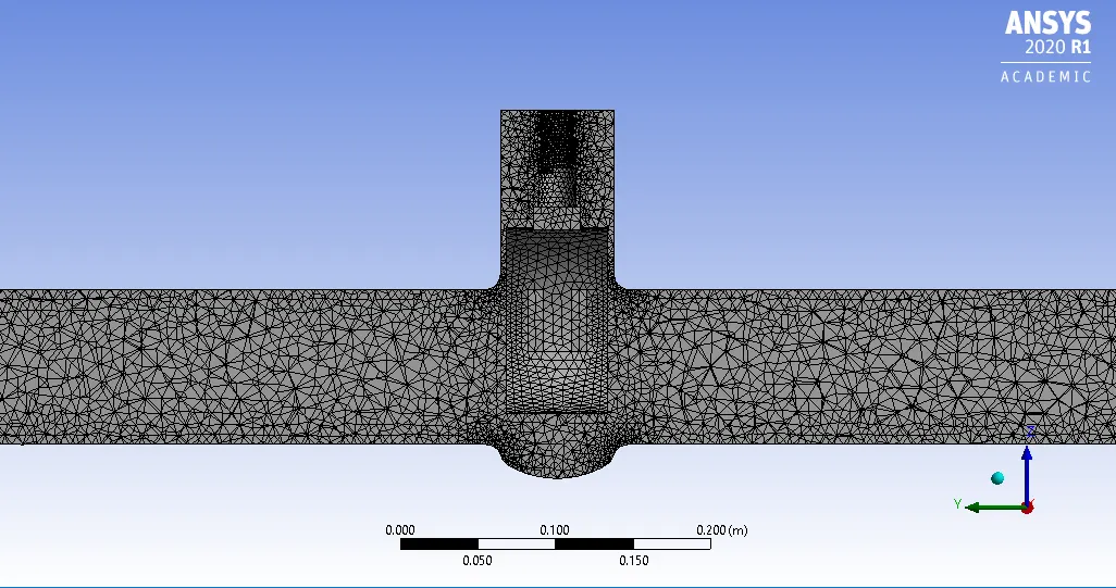
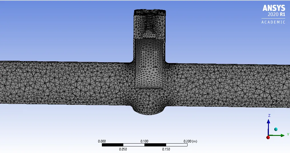
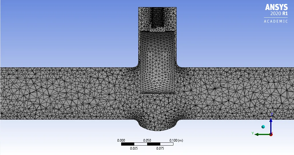
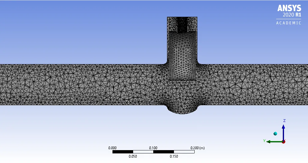
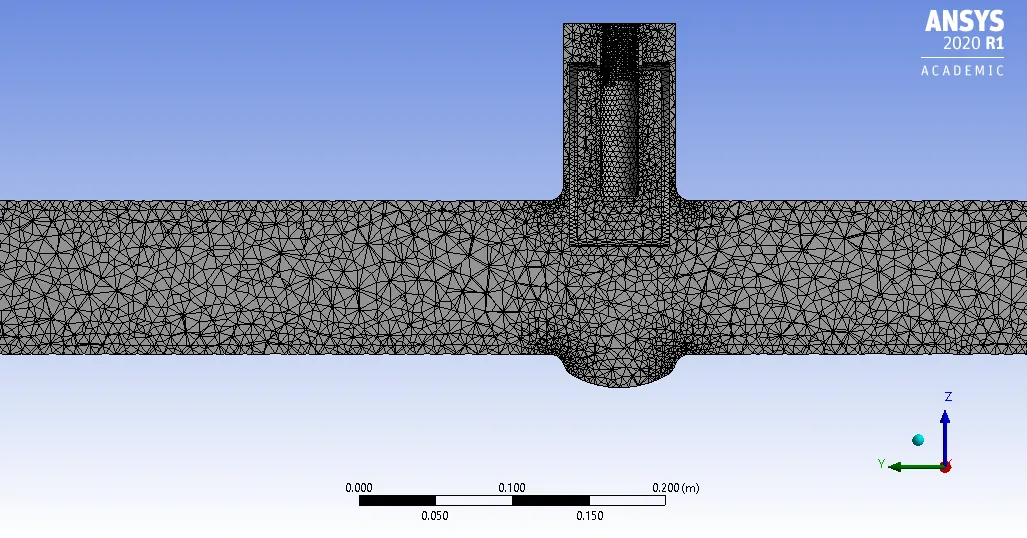
#Meshing done is Mesh Module
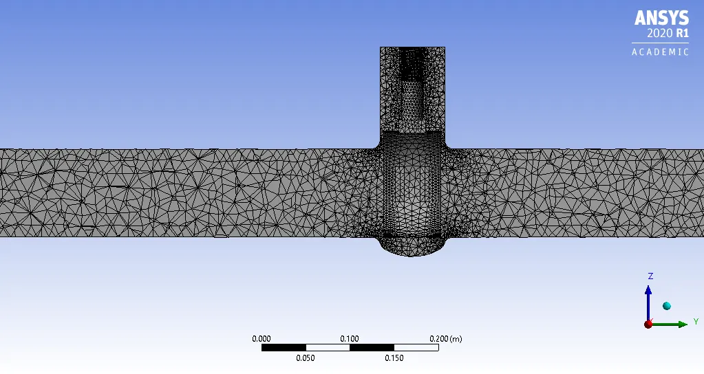
Global Mesh size--0.8 metre.
#Setup:
General:
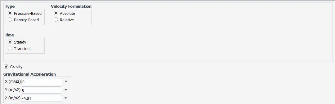
Model Used:
K epsilon ,Realizable,Scalable Wall Function.
Material Used:
Water
Boundary Condition:
Inlet:
Pressure-inlet
Gauge Total Pressure-10 Pascal.
Outlet:
Pressure-Outlet
Gauge Pressure- 0 Pascal.
Solution Method:
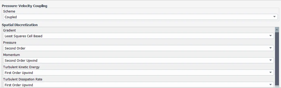
--Intialize problem by Standard Initialization.
--Create plane along the centre axis of fluid volume.
--Plot contour for Velocity and Create an Animation.
--Hit calculate and Run it for 200 iteration.
##Analyze Results in PostCFD at last.
-----------------------------------------*****------------------------------------------------
Parametric Study:
Parametric study means studying the effect of change of design parameter on geometry and solution.
The parameters can include dimensional parameters. Parametric studies allow you to nominate parameters for evaluation, define the parameter range, specify the design constraints, and analyze the results of each parameter variation.
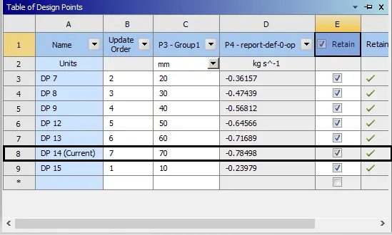
Like in this challenge,Lift of Gate valve Disc is set as parameter .We will study the effect of change in disc lift on velocity,pressure drop in gate valve.
Flow coefficient (Cv)and Flow factor(Kv):
Cv--The flow coefficient of a device is a relative measure of its efficiency at allowing fluid flow. It describes the relationship between the pressure drop across an orifice valve or other assembly and the corresponding flow rate.
Mathematically the flow coefficient Cv (or flow-capacity rating of valve) can be expressed as :
`Cv=Q*sqrt((SG)/(DeltaP)`
where:
- Q is the rate of flow expressed in US gallons per minute
- SG is the specific gravity of the fluid (for water = 1),
- `DeltaP` is the pressure drop across the valve (expressed in psi).
Kv--
The metric equivalent flow factor (Kv; commonly used in Europe and Asia) is calculated using metric units :
- `K_v=Q*sqrt((SG)/(DeltaP)`
where
- Kv is the flow factor (expressed in
 ).
). - Q is the flow rate (expressed in cubic metres per hour [
 ]),
]), - SG is the specific gravity of the fluid (for water = 1),
- ∆P is the differential pressure across the device (expressed in [bar]).
--Kv can be calculated from Cv using the equation:

-----------------------------------------*****************-------------------------------------------
##We will study effect of change in Lift of Gate valve disc.
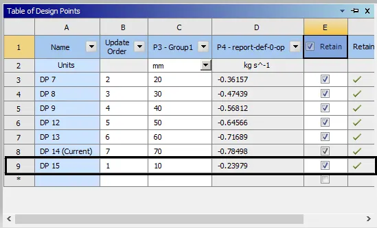
Range vary from 10 percent to 80 percent lift .
Increase in 10 mm lift represent 10 percent disc opening.
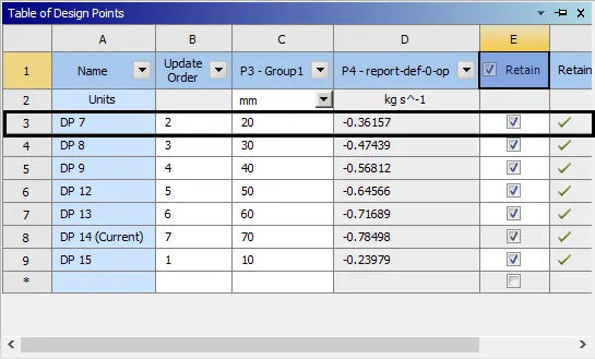
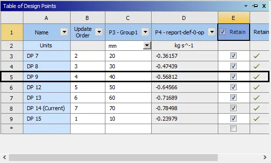
Total cases considered are 8.
Only in the first case no parameter is set.Only Disc is lifted by Move tool in Spaceclaim without inclusion of Parameter.
After that all 7 cases have parameter enabled,so 10 mm lift for first case will add up in all cases.Like 10+10 mm lift for 20 percent valve opening and like this continue.
##Results:
Case-1:
For 10 mm lift:(10% open)
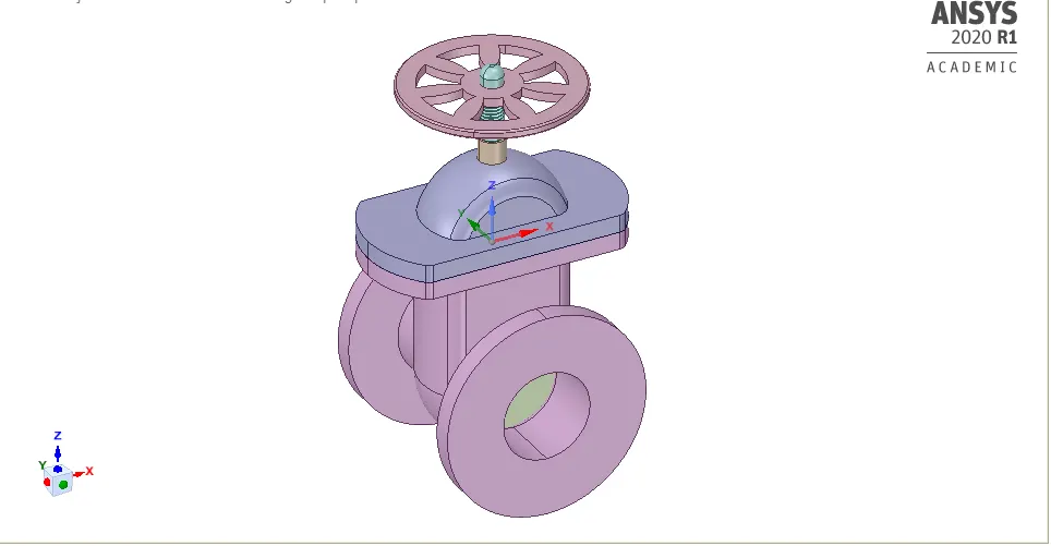
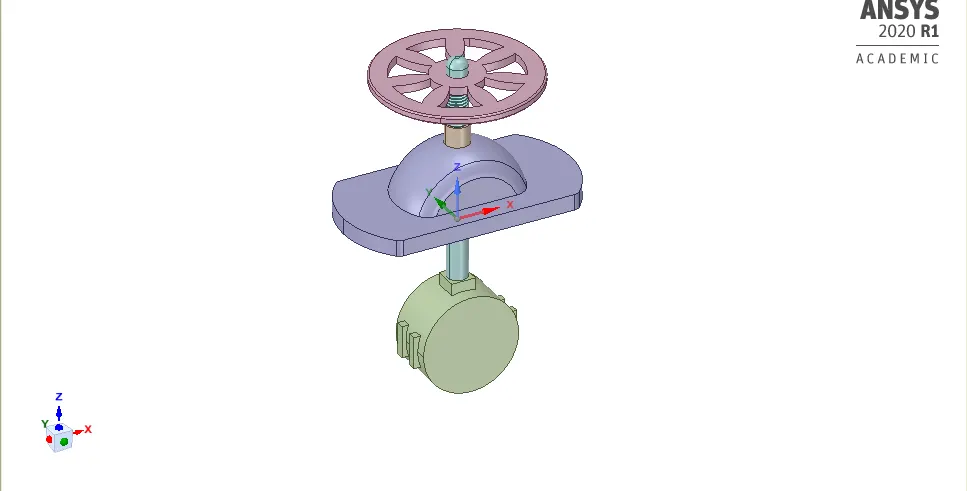
#Fluid volume:
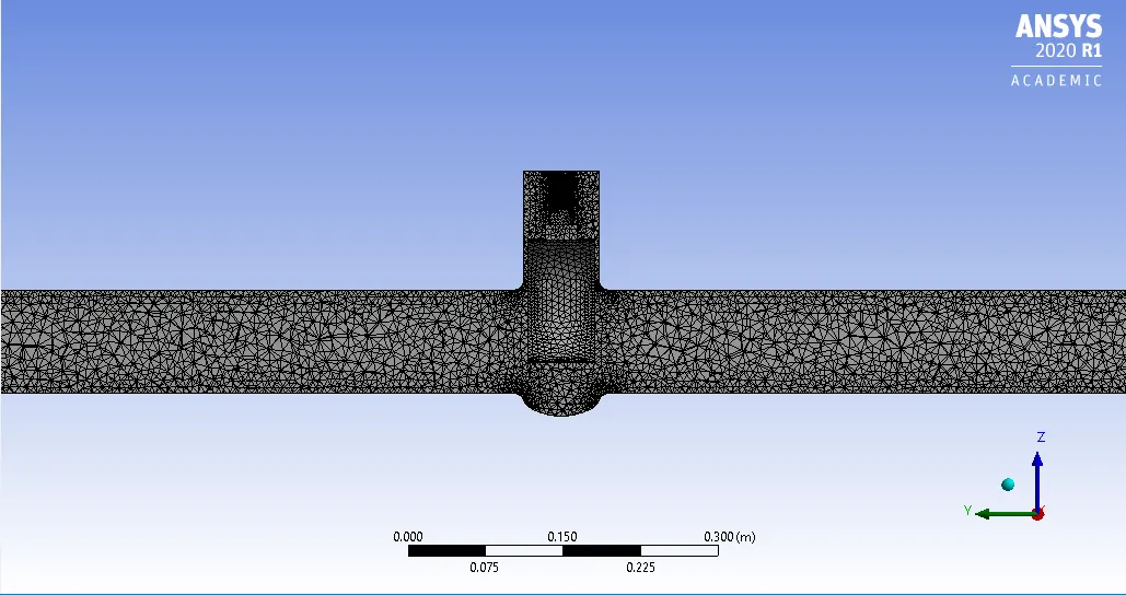
#Sectional view of Mesh
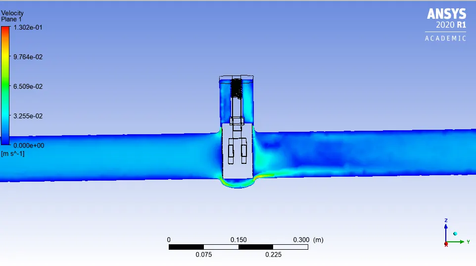
#Velocity plot:
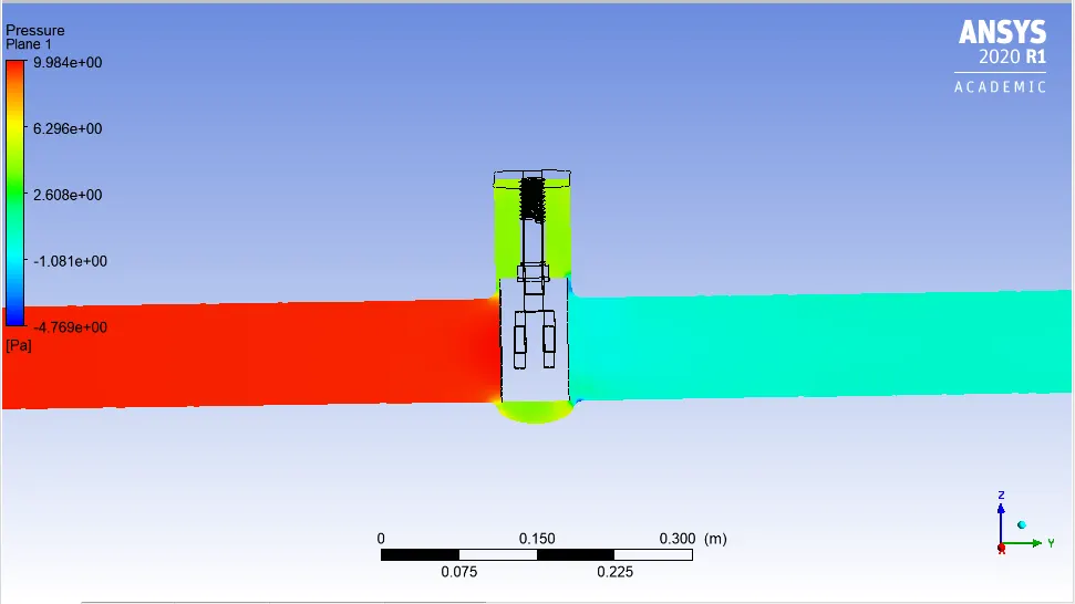
#Pressure Plot:
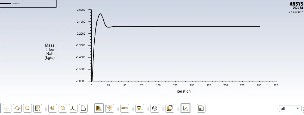
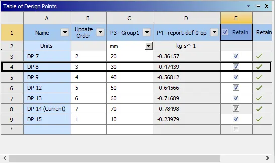
#Mass flow rate Plot:

#Calculation of Flow coefficient(Cv) and Flow factor(Kv):
Since,
`Cv=Q*sqrt((SG)/(DeltaP)`
Here,
Q=2.23 gallons US per minute;
SG=1;
`DeltaP`=14.50519 psi;
So,
Cv=0.586 ;
And also,
Kv=0.865*Cv;
Kv=0.506;
Case-2 :
For 10+10 mm Lift:(20% open)
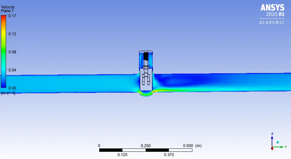
#Velocity PLot:
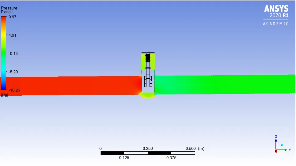
#Pressure PLot:
#Calculation of Flow coefficient(Cv) and Flow factor(Kv):
Since,
`Cv=Q*sqrt((SG)/(DeltaP)`
Here,
Q=3.8 gallons US per minute;
SG=1;
`DeltaP`=14.50515 psi;
So,
Cv=0.997;
And also,
Kv=0.865*Cv;
Kv=0.863;
Case-3:
For 10+20 mm Lift:(30% open)
#Velocity Plot:
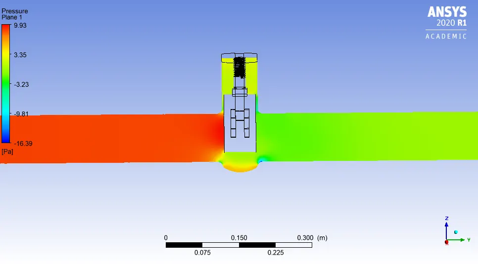
#Pressure Plot:
#Calculation of Flow coefficient(Cv) and Flow factor(Kv):
Since,
`Cv=Q*sqrt((SG)/(DeltaP)`
Here,
Q=5.73 gallons US per minute;
SG=1;
`DeltaP`=14.50505 psi;
So,
Cv=1.505 ;
And also,
Kv=0.865*Cv;
Kv=1.301;
Case-4:
For 10+30 mm Lift:(40 % open)
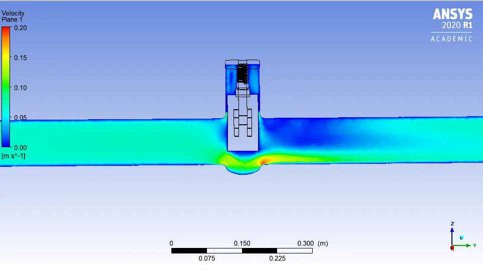
#Velocity Plot:
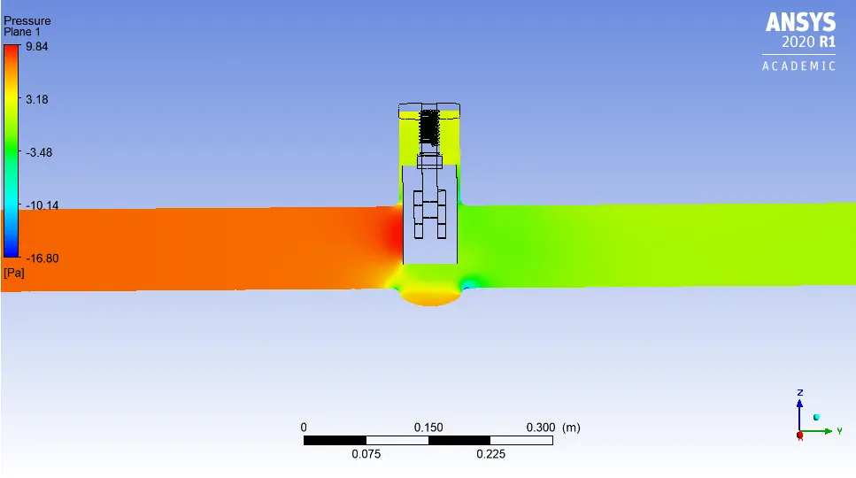
#Pressure Plot:
#Calculation of Flow coefficient(Cv) and Flow factor(Kv):
Since,
`Cv=Q*sqrt((SG)/(DeltaP)`
Here,
Q=7.5 gallons US per minute;
SG=1;
`DeltaP`=14.5049 psi;
So,
Cv=1.969 ;
And also,
Kv=0.865*Cv;
Kv=1.703;
Case-5:
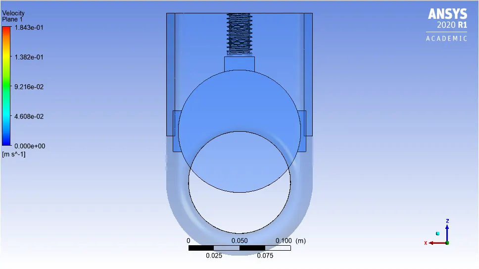
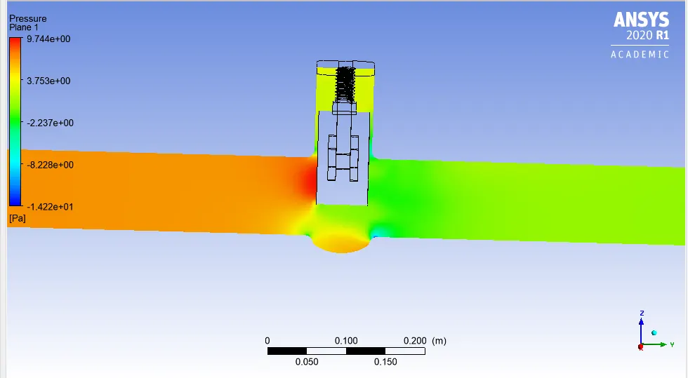
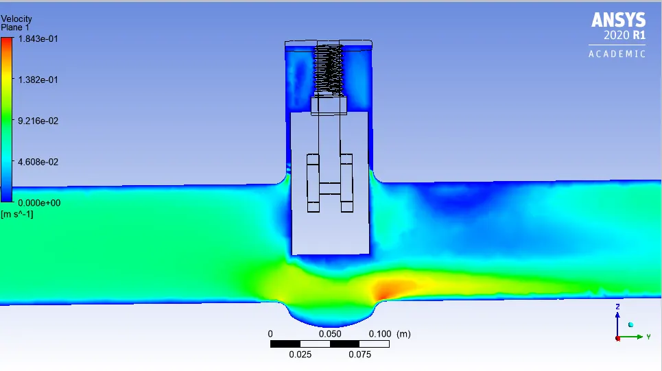
For 10+40 mm Lift:(50% open)
#Pressure Plot:
#Velocity Plot:
#Calculation of Flow coefficient(Cv) and Flow factor(Kv):
Since,
`Cv=Q*sqrt((SG)/(DeltaP)`
Here,
Q=9 gallons US per minute;
SG=1;
`DeltaP`=14.5048 psi;
So,
Cv=2.36 ;
And also,
Kv=0.865*Cv;
Kv=2.044;
Case 6:
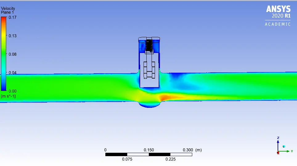
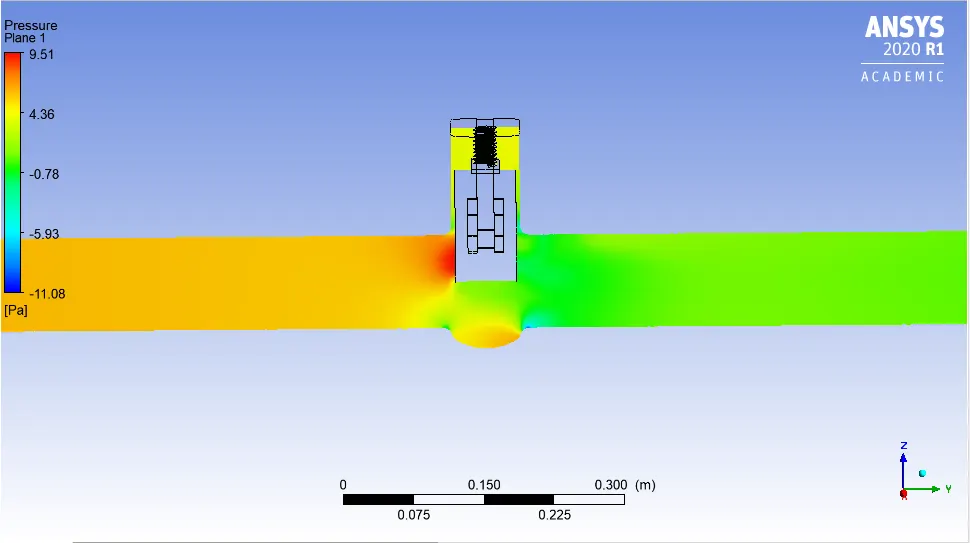
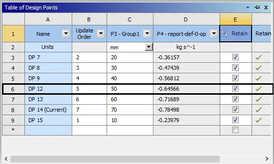
For 10+50 mm Lift:(60% open)
#Calculation of Flow coefficient(Cv) and Flow factor(Kv):
Since,
`Cv=Q*sqrt((SG)/(DeltaP)`
Here,
Q=10.23 gallons US per minute;
SG=1;
`DeltaP`=14.5046 psi;
So,
Cv=2.686 ;
And also,
Kv=0.865*Cv;
Kv=2.323;
Case-7:
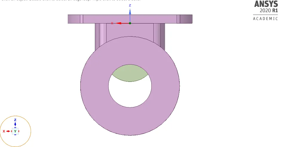
For 10+60 mm Lift:(70% open)
#Velocity Plot:
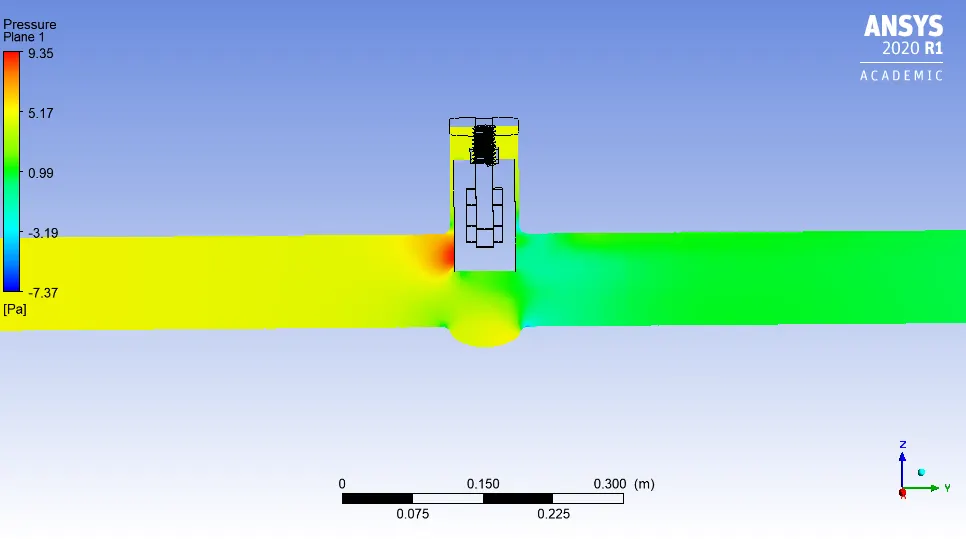
#Pressure Plot
#Calculation of Flow coefficient(Cv) and Flow factor(Kv):
Since,
`Cv=Q*sqrt((SG)/(DeltaP)`
Here,
Q=11.36 gallons US per minute;
SG=1;
`DeltaP`=14.5045 psi;
So,
Cv=2.982 ;
And also,
Kv=0.865*Cv;
Kv=2.580;
Case-8:
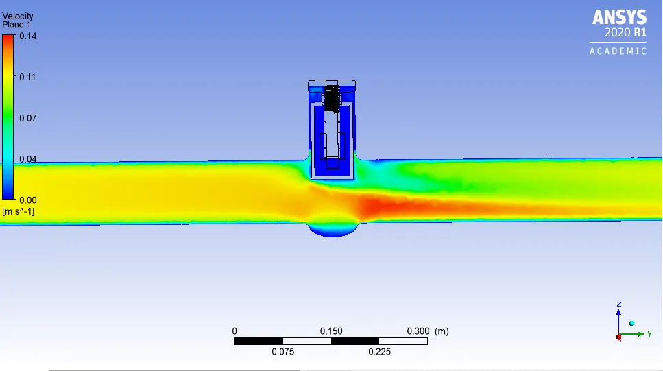
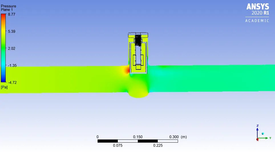
For 10+70 mm Lift:(80% open)
#Velocity Plot:
#Pressure Plot:
#Calculation of Flow coefficient(Cv) and Flow factor(Kv):
Since,
`Cv=Q*sqrt((SG)/(DeltaP)`
Here,
Q=12.44 gallons US per minute;
SG=1;
`DeltaP`=14.5044 psi;
So,
Cv=3.266 ;
And also,
Kv=0.865*Cv;
Kv=2.825;
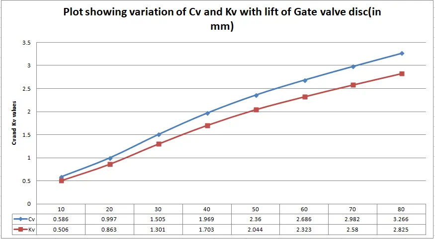
#Cv and Kv Plot vs Disc lift(in mm)
#Findings:
Basically Gate valve is used in aplications where there is need to either start or stop the flow completely,it is normally not used to control the flow in a pipe.
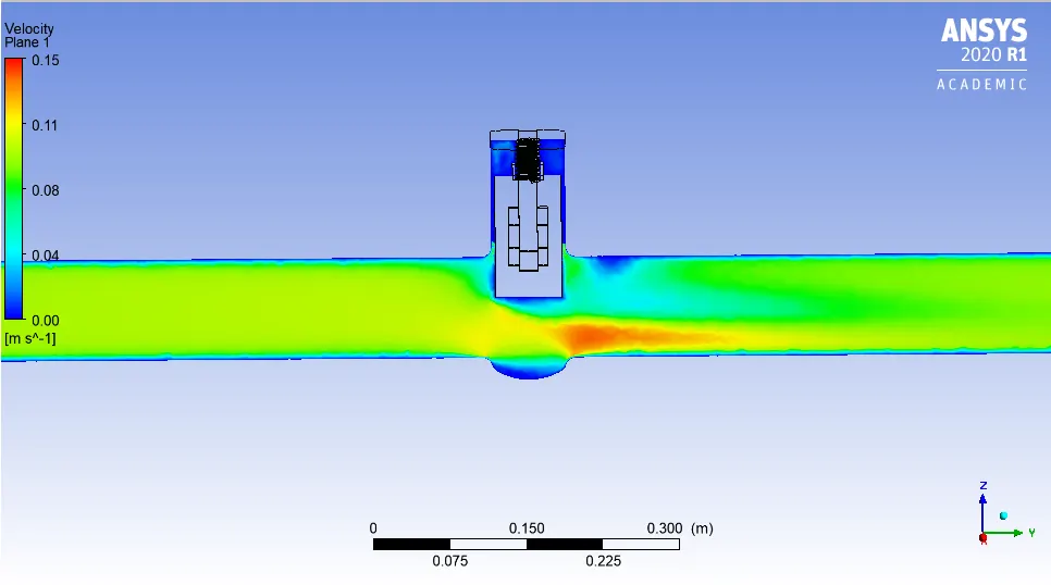
Even though we have studied in this challenge ,the changes in pressure and velocity and areas where high velocity and prssure zones are created with the movement of disc from 10 to 80 percent opening of valve.
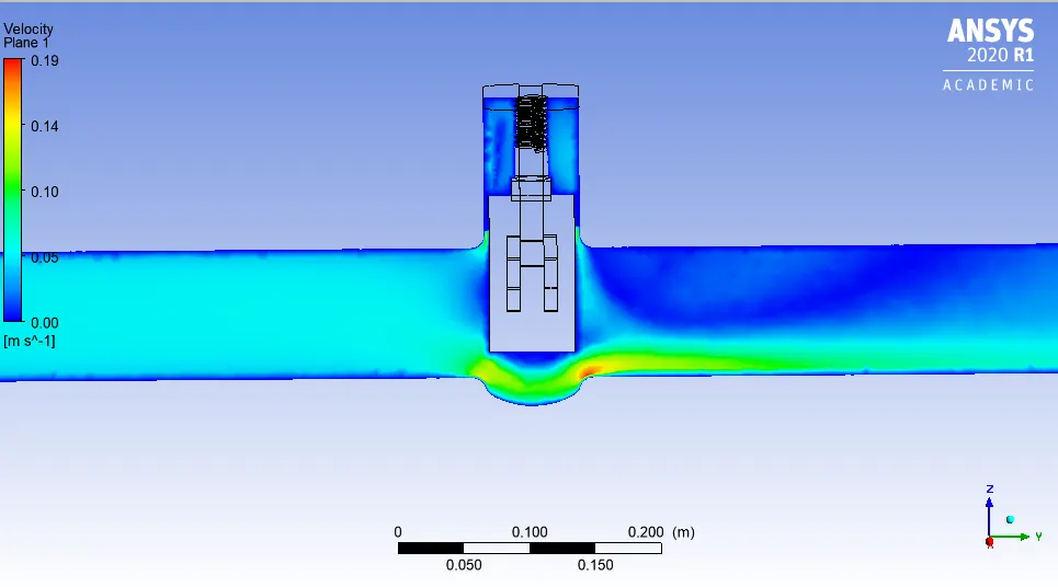
As we can see from pressure and velocity plot of all the above cases,when the disc was open slight say 10 mm,the region where there is a opeing .There velocity is high,which can cause erosion of the disc if this valve is used for control of flow.Because for completely stopping the flow,the disc should be in 100 percent contact with the bottom body,otherwise the Valve will leak.The pressure drop was maximum when disc lift was minimum.
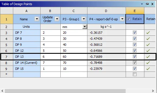
As expected Mass flow rate and flow coefficient both increases with th increase in opening of the valve disc.Plot shown above is the evidence.