FUNCTION EVALUATION AND COMPARISON OF SUSPENSION SYSTEM USING SIMULINK
AIM:
EVALUATION OF FUNCTION AND TO COMPARE AND STUDY DIFFERENT TYPES OF SUSPENSION SYSTEMS
OBJECTIVES:
1) Evaluate and plot the given function using Simulink
2) Comparison of various suspension systems
GIVEN FUNCTION:
`y(x) = (x-1).(x-3)^2.(x-9)^2`
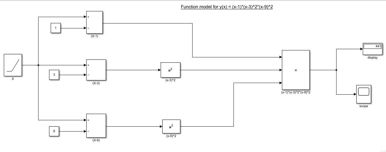
SIMULINK MODEL-1:
BLOCKS USED IN THE MODEL:
a. Ramp – For varying the x value to plot the function
b. Constant – Representing the values, ‘1, 3 & 9’
c. Subtract – For solving the equation
d. Square – For squaring the solved equation
e. Product – To evaluate and generate the function output
f. Display – To show the evaluated value
g. Scope – To trace the change in values during increment in ‘x’ and plot the graph
PROCESS EXPLANATION:
a. The x value in Ramp is taken and sent to (x-1), (x-3) & (x-9)
b. The values inside (x-3) & (x-9) box are squared
c. The values from (x-1), (x-3)^2 & (x-9)^2 are sent to product block for multiplication
d. The output received from the product block is now displayed in Display block
e. All the steps run like a loop structure till x reaches the desired run second given by the user
OUTPUT:
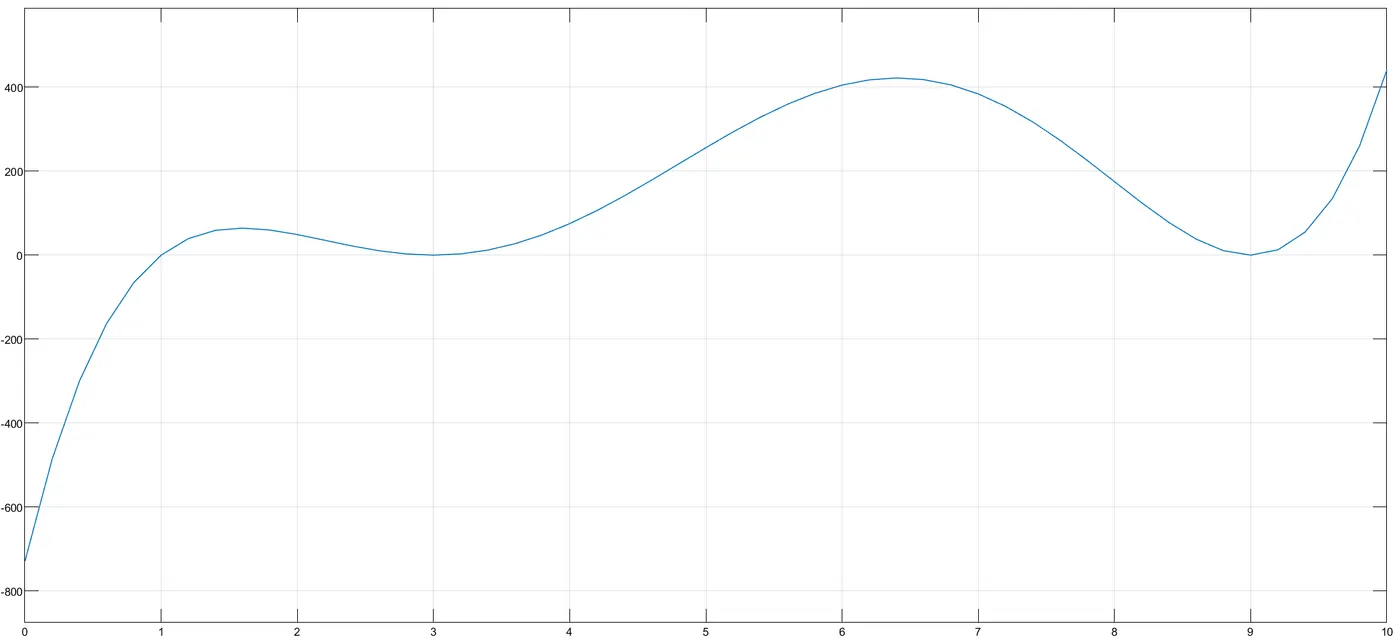
The x value varies from 0 to 10.
SIMULINK MODEL-2:
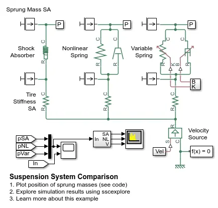
This model shows comparison of three different suspension system used in automobile, this model gives the idea about the vibrations generated by velocity source.
QUESTION AND ANSWERS:
1. What is the objective of the simulation, what are the similarities and difference between the three systems understudy?
The objective of the stimulation is to provide certain range of input velocity for analysing sprung mass position during vibration for all different spring damper arrangement.
Damping systems:
In this model, we have three different arrangement of spring and damper.
A) Shock Absorber
The arrangement of spring and damper are linear, the block represent spring-damper system commonly used in damping vibration in mechanical systems. An internal force acts between R and C, the force is sum of spring siffness, damping, columnb friction, etc.

B) Non-linear translational spring and damper
The arrangement of spring and damper are non-linear i.e parallel, the ports R and C are mechanical translational conserving ports.

C) Variable translational spring and damper
The arrangement of spring and damper are non-linear with respect to stiffness 'K' and damping coefficient 'B'

2. What are the obsevations made from the results ?
The observations after stimulating the model is the vibrations of the three asystems and the position of sprung mass durring the vibration frequency variation.
Result-1:
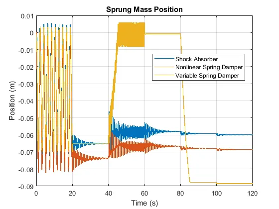
In this plot we can observe that the position of the spring and mass during the change in velocity. Initially the spring gets vibrated during the input velocity and gets damped out by damper.
1) Till (t=20 sec) the vibrations of all the three systems are same and then gets damped out.
2) From (t=40-60 sec) the variable spring vibrates and damps out except the suspension and linear one which vibrates till (t=70 sec) and then gets damped out.
3) There are very small vibrations in between (t=80-100 sec) interval suspension and linear one and then gets damped out.
Result-2:
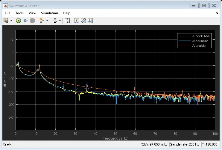
From the plot, we can observe the vibration frequency(Hz) of the springs in three systems from the noise (dB) during the input velocity.
3. How the oscillating velocity is generated?
The oscillating velocity is created using sine wave and pulse genrator block.
Sine Wave:
The Sine Wave block outputs a sinusoidal waveform. The block can operate in time-based or sample-based model.

Pulse generator:
he Pulse Generator block generates square wave pulses at regular intervals. The block waveform parameters, amplitude, pulse width, period, and phase delay, determine the shape of the output waveform.

MODEL FILE:
https://drive.google.com/file/d/1lya_nYCR9Fa43DgM32Gywkt-LIvGqTg4/view?usp=sharing
CONCLUSION: AFTER STIMULATING THE MODELS IN SIMULINK,WE CAN EASILY SOLVE AND REPRESENT THE MATHEMATICAL FUNCTION. WE ALSO GET TO UNDERSTAND THE BEHAVIOUR (VIBRATIONS, DAMPING AND FREQUENCY) OF SUSPENSION SYSTEM USED IN AUTOMOBILE DURING THE CHANGE IN VELOCITY.
REFRENCES:
https://in.mathworks.com/help/physmod/sdl/ug/suspension-system-comparison.html?s_tid=srchtitle