Frontal Crash Simulation
Frontal crash-BIW
- Check unit system and either follow[Mg mm s] or [Kg mm ms].
- Create appropriate interface ,friction 0.2 and recommended parameters.
- Make sure of no penetrations and intersection.
- Correct rigid bodies if any issues.
- Create rigid wall with friction 0.1.
- Compare the model weight with the full scale 300k nodes model and use added masses to reach target weight 700kg while getting CG about the required range.
- Initial velocity 35 mph.
- Use model checker to ensure good quality.
- Time-step :0.5 to 0.1 microseconds.
- Run 80 ms.
Output requests:
- Sectional force in the rails at location of indicated node 174247.
- Axial force received on the rails from bumper.
- Shotgun cross sectional forces.
- A pillar cross section.
- Acceleration curve received on the accelerometer at base of B pillar (on B pillar rocker).
- Intrusions on the dash wall 66695,66244.
Note:
- Submit your simulation files including time and h3d files.
- Plot energies and notice any difference.
- Explain your errors and how to rectify?
Click here to access the models/radioss files.
Click here to download the full car model with 300k elements
Note: Don't attach the google drive link of the completed model/simulation files in the challenge box. Attach the model/files in the challenge assets option provided.
Your Answers
AIM: to perform frontal crash on the given model and study and analyse the behavior of the model.
OBJECTIVE:
- Check unit system and either follow[Mg mm s] or [Kg mm ms].
- Create appropriate interface ,friction 0.2 and recommended parameters.
- Make sure of no penetrations and intersection.
- Correct rigid bodies if any issues.
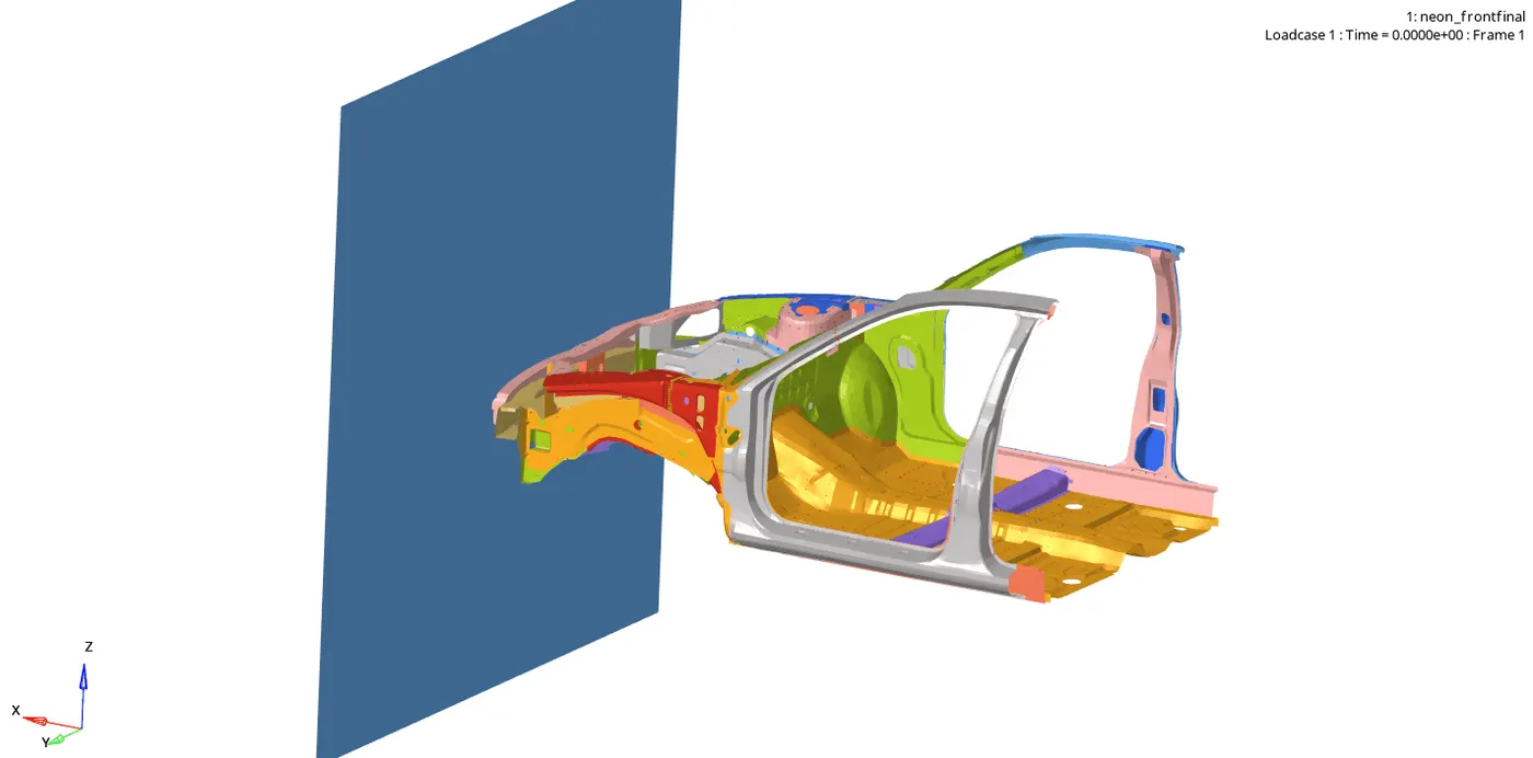
- Create rigid wall with friction 0.1.
- Compare the model weight with the full scale 300k nodes model and use added masses to reach target weight 700kg while getting CG about the required range.
- Initial velocity 35 mph.
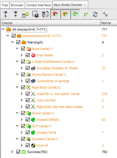
- Use model checker to ensure good quality.
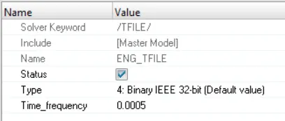
- Time-step :0.5 to 0.1 microseconds.
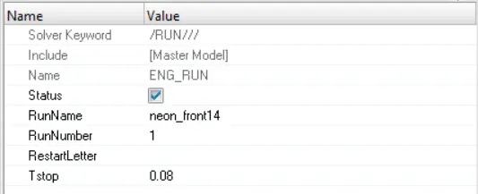
- Run 80 ms.
to obtain desired results an output request has to created.
Output requests:
- Sectional force in the rails at location of indicated node 174247.
- Axial force received on the rails from bumper.
- Shotgun cross sectional forces.
- A pillar cross section.
- Acceleration curve received on the accelerometer at base of B pillar (on B pillar rocker).
- Intrusions on the dash wall 66695,66244.
PROCEDURE:
- Check unit system and either follow[Mg mm s] or [Kg mm ms].
for this project, I choose to use [Mg mm s N].

- Creating appropriate interface ,friction 0.2 and recommended parameters.
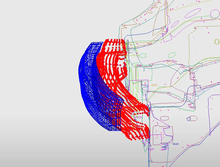
In this case 2 contact interfaces have to be created.
1. bumper contact interface.
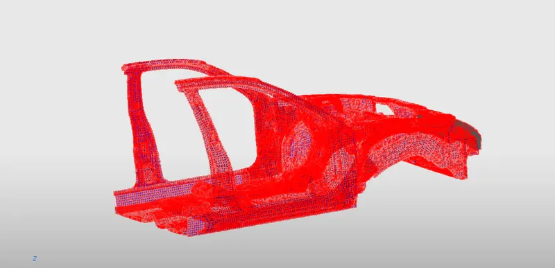
2. self contact interface.
1.The bumper interface is created inorder to get the axial force in the bumper rail is requested.
to create the bumper interface in hypercrash,
Right click in the Browser > create new > A-C > contact interface > type 7
since we need the axial load in the bumper rail, we make the bumper rail as the slave and the bumper as the master.
hence, we select all the nodes in the "bumper rail" under "slave nodes" and all the nodes on the "bumper" under "Master nodes".
2. creating interface for self contact.
to create the self contact interface in hypercrash,
Right click in the Browser > create new > A-C > contact interface > type 7.
select the whole model as the master as well as the slave since it is a self contact interface.
- check for penetrations and intersections.
to check for penetrations and intersections, the "penetration checker " has to be used.
to access the penetration checker,
tool > penetration checker.
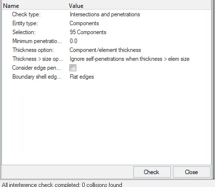
hence no penetrations and intersections were found.
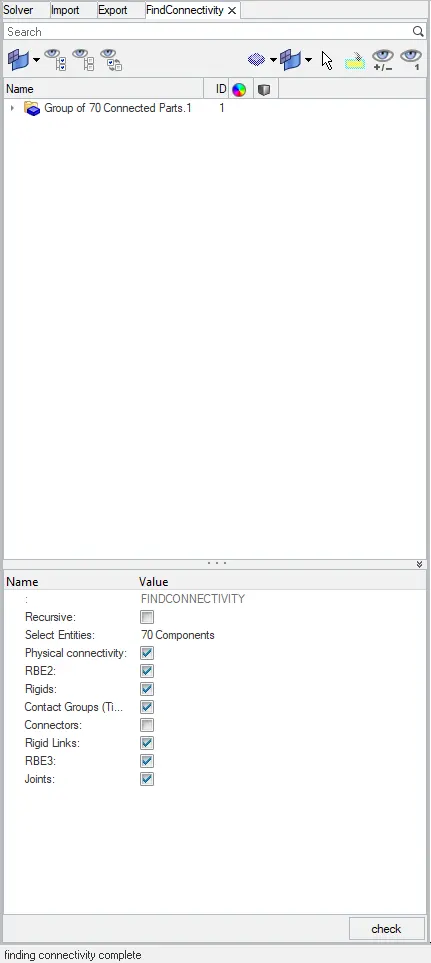
- Correct rigid bodies if any issues.
checked for connectivity, no issues found.
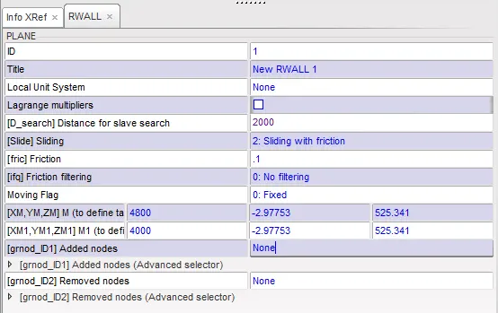
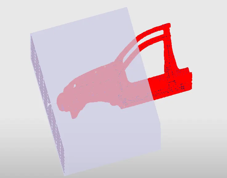
- Create rigid wall with friction 0.1.
to create a rigid wall,
right click in the browser > create new > rigid wall > plane
select the node which is in the most front and create a rigid wall from there.
select "sliding with friction"
add calue of friction i.e "0.1" .
Dsearch = 2000
- Compare the model weight with the full scale 300k nodes model and use added masses to reach target weight 700kg while getting CG about the required range.
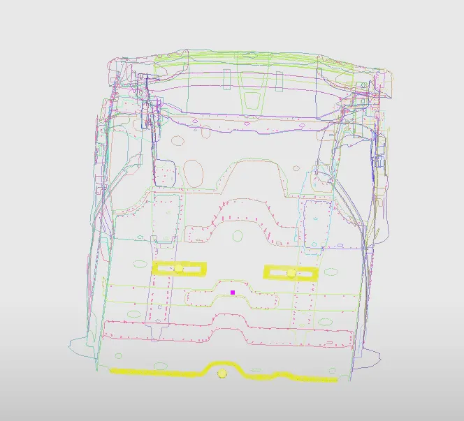
inorder to reach the 700kg target mass, mass has to be added at certain locations.
we have added mass of driver, co-driver and passengers.
driver = 130 kg = 0.13 Mg
co-driver = 130 kg = 0.13 Mg
passangers = 250 kg = 0.25 Mg
- Initial velocity 35 mph.
to create an initial velocity,
right click in the browser > create new > initial velocity
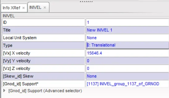
since the units being used is [Mg mm s N], the velocity is 15646.7 mm/s which is equal to 35 Mph.
- Use model checker to ensure good quality.
- Time-step :0.5 to 0.1 microseconds.
- Run 80 ms.
SIMULATION:
Output requests:
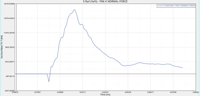
- Sectional force in the rails at the location of indicated node 174247.
to study the sectional forces in the rails at location 174247, a section has to be created. but first, a frame has to be created. since the sectional force at 174247 has to be studied, a frame at 174247 should be created. to create a frame,
right click in the browser > create new > system > frame.
the type of the frame should be " Moving frame" since the vehicle is in motion. since the force at the node 174247 is to be observed, node 174247 is set at 'node 1'. while creating the frame, the 'Node 1' defines the origin, 'node 2' creates the X-axis and "node 3" creates the y axis. the z axis is calculated depending on the positions on X and Y axes.
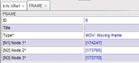
after the frame has been created, a 'Section' has to be created. to create a section,
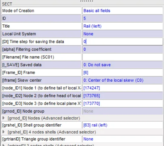
right click in the browser > create new > sections > default section.
the nodes selected for the frame has to be also be assigned to section.after the section has been created, the frame created has to be assigned to the Frame using the 'Frame ID'.
Graph:
- Axial force received on the rails from bumper.
to study the axial forces received on the rails of the bumper during the impact, a contact interface has to be created.
to create the contact interface,
right click in the browser > create new >contact interface > Type 7.
the axial force received on the front bumper can be observed from the "Data History".
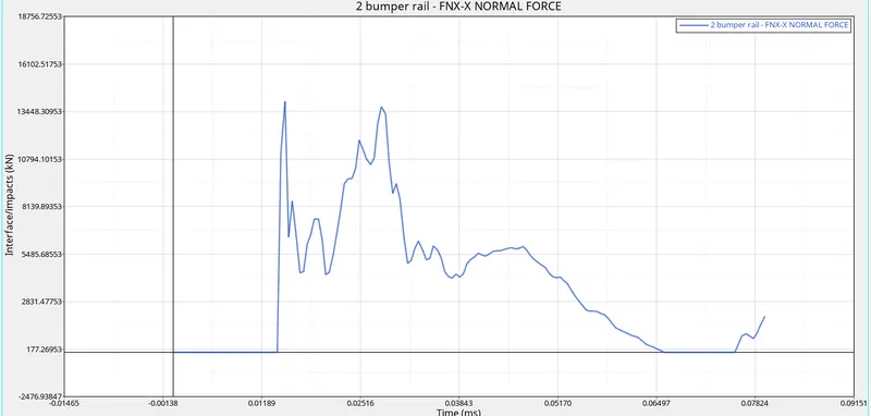
we observe that there is a flat spot and then an increase in the graph, this is because the bumper rail isnt in contact for a while and then starts colliding again.
- Shotgun cross sectional forces.
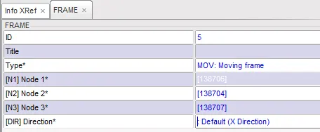
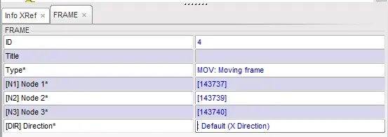
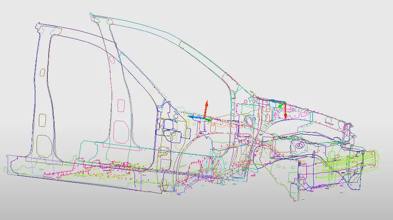
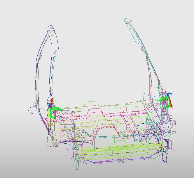
to study the cross sectional forces at the shotguns, we need to create a section on the shotguns. in order to create a section, a frame need to be created which will be assigned to the section.
to create the frame at the sections of the shotgun,
right click in the browser > create new > system > frame.
left frame: Right frame:
frame location:
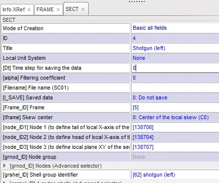
to create sections,
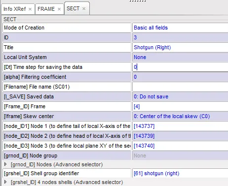
right click in the browser > create new > sections > default section.
the frames are assigned to their respective sections.
left section: right section:
section locations:
Graph:
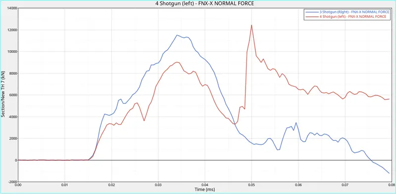
by looking at the graph we observe that the right shotgun initially had the larger deformation but as it goes ahead we see that the graph goes down below 0. this is because the section which was made to observe the deformation, moved down from its initial position. while the left shotgun had a major bend which spiked up the graph and the section displaced above its initial position.
- A pillar cross section.
to study the cross sectional forces at the A pillars, we need to create a section on the A pillars. in order to create a section, a frame need to be created which will be assigned to the section.
to create the frame at the sections of the A pillars,
right click in the browser > create new > system > frame.
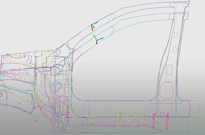
to create sections,
right click in the browser > create new > sections > default section.
the frames are assigned to their respective sections.
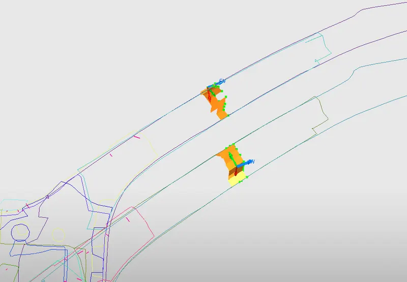
Graph:
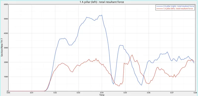
from the graph we understand that the right side of the vehicle has taken a higher load when compared to the left side of the car.
- Acceleration curve received on the accelerometer at base of B pillar (on B pillar rocker).
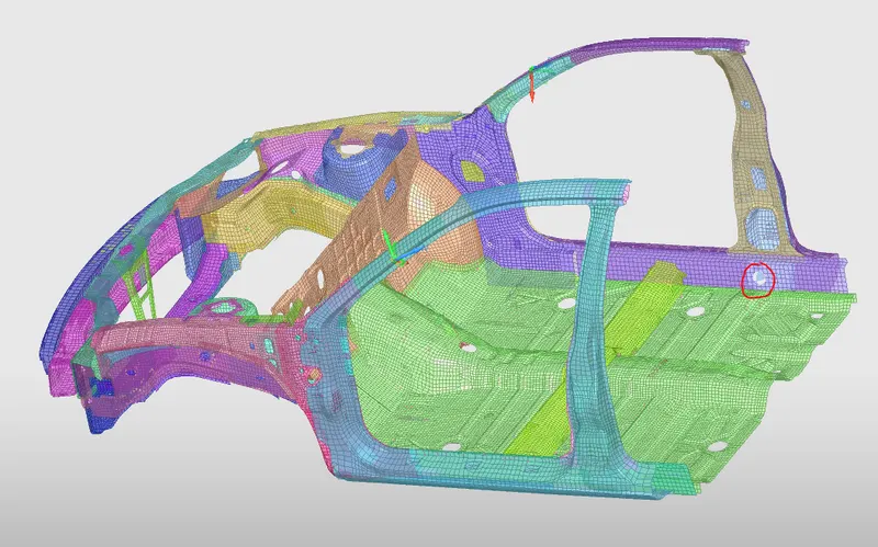
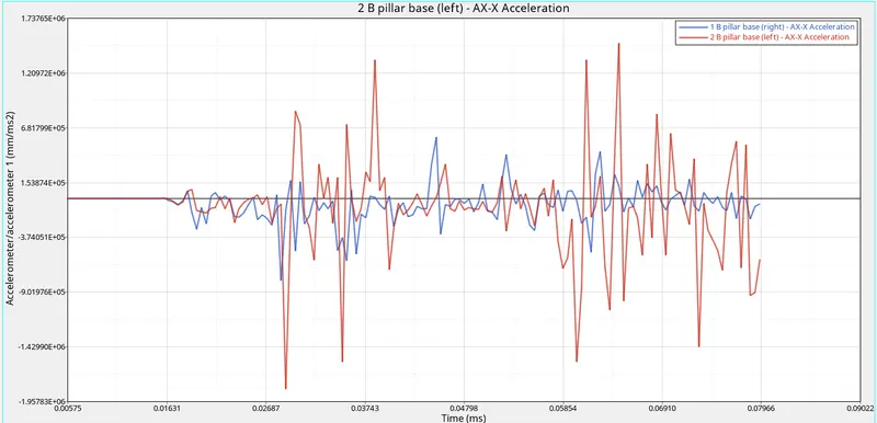
there are 2 accelerometers placed on each rail of the B pillar base. we can observe that the left side has a major fluctuation of acceleration.
- Intrusions on the dash wall 66695,66244.
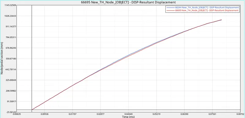
the intrusions were created at the nodes 66695 and 66244. a skew was also created and was assigned to the intrusions to observe the displacement.
from the intrusions, we observe that the nodes have displaced a distance of 988mm. these nodes were created where the pedals or the co-drivers legs are usually present. by observing the deformation, we understand that the nodes have displaced a distance of 988mm which is dangerous as the legs of the person seating in that position could take a heavy damage.
CONCLUSION:
frontal crash has been performed on the given model and the crash analysis data has been analysed and studied.