Foundation Design using SAFE
ANSWER:
COMPLETE STEPWISE PROCEDURE TO DESIGN ISOLATED FOOTING AND PILE FOUNDATION USING SAFE
1. ISOLATED FOOTING:
- Initial Design Setup
- Download the SAFE software from the official CSI website, to begin with, the project.
- Locate the software in your machine at the desired disk.
- Then, open the software after installing it.
- Then, you will find a similar user interface as included in ETABS.
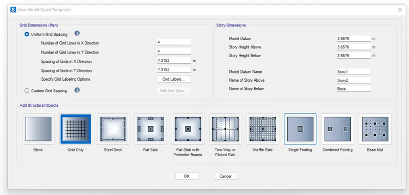
- So, click on the new model option as we do while designing in ETABS.
- Then, there will be a few footing templates made available to you by the software.
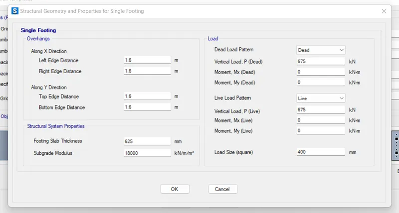
- So, choose the isolated footing option from the list and feed the footing details.
- In the detail section, you need to insert the length, breadth, and depth of footing.
- At the same time, you can also define the load type and intensity in the same section.
- It saves you time from having to apply load manually after modeling.
- Define Material Properties
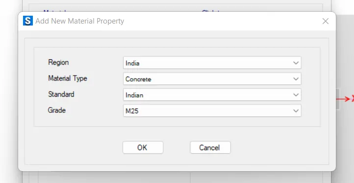
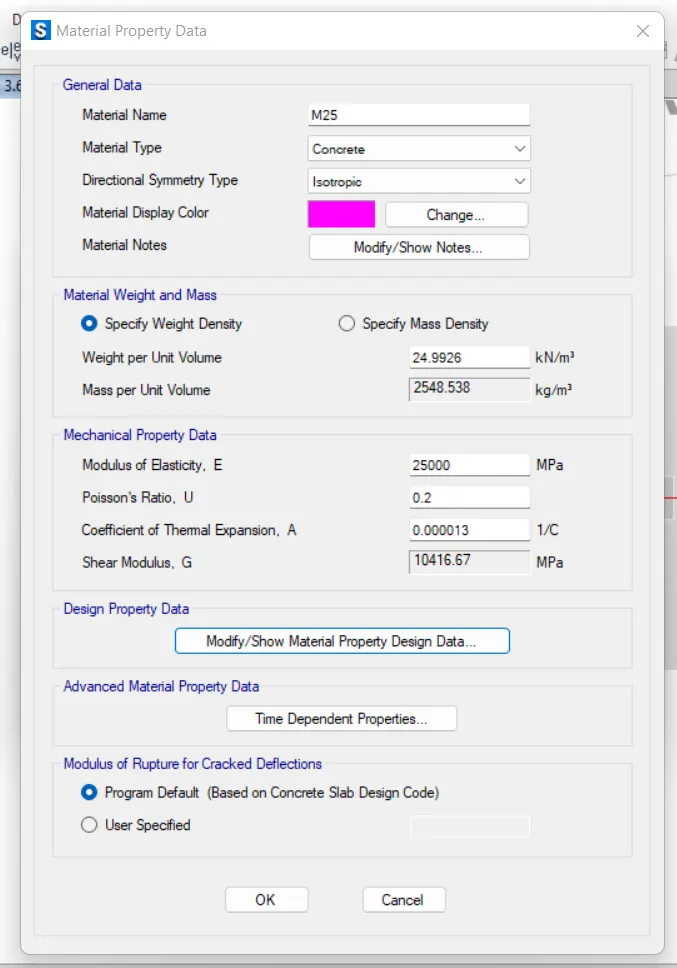
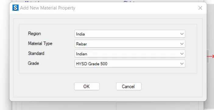
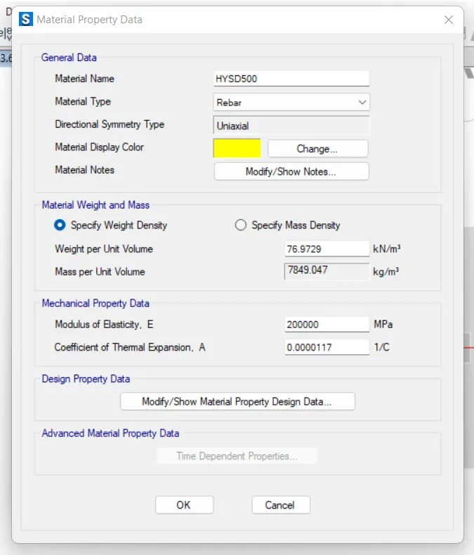
- Like we did in ETABS, we need to define the material properties in an exact manner.
- However, we don't need to have shear ties for footings. So, don't define fe415. Just define concrete and fe500 and that's it.
- The same is shown below:
M25
FE 500
- Define Section Properties
- This can also be done the same way as ETABS.
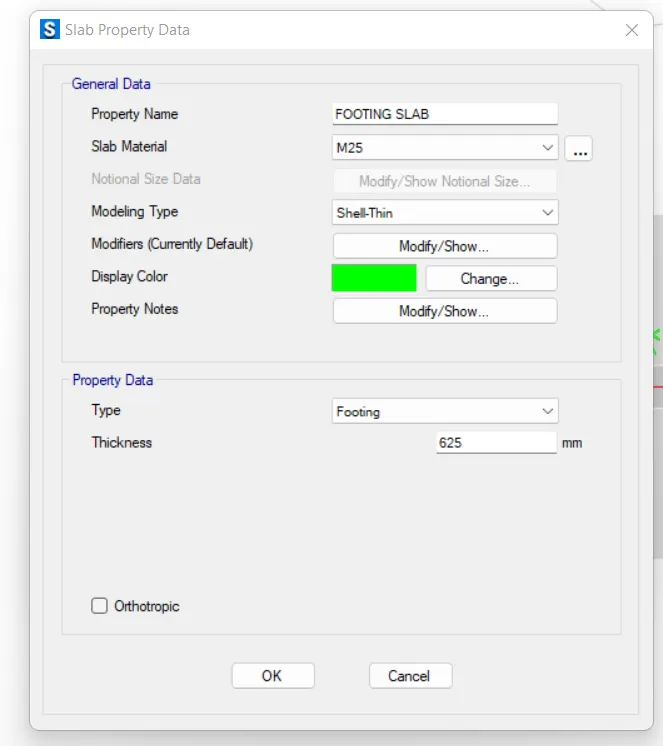
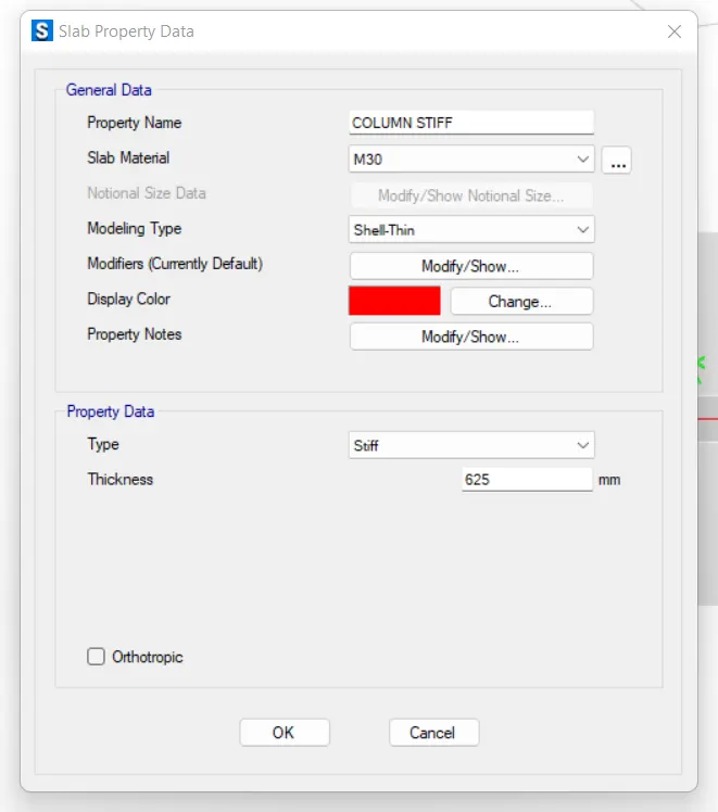
- But here, we need to define two different types of slabs. One is the footing slab and the other is the stiff slab for the column area over the footing.
- However, the depth of both the slabs shall remain the same as calculated from the pressure formula.
- Also, make sure to select the property type as footing and stiff respectively while defining the slabs.
Footing Slab
Stiff Slab (for the column portion)
- Define the Load Combinations
- The procedure is exactly the same as we do in ETABS.
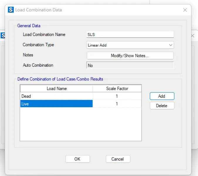
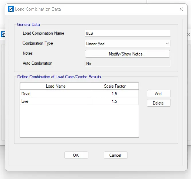
- However, we need to define two types of load combos for footing that are service load and ultimate load combinations.
- In the service load combination (SLS) total unfactored column load will be accounted for.
- Whereas in the case of ULS, a factor of 1.5 shall be multiplied by the dead and live loads.
- So, the same is done as follows:
SLS Load Combo
ULS Load Combo
- Load Assignments
- We have already assigned loads while defining the footing section in the beginning.
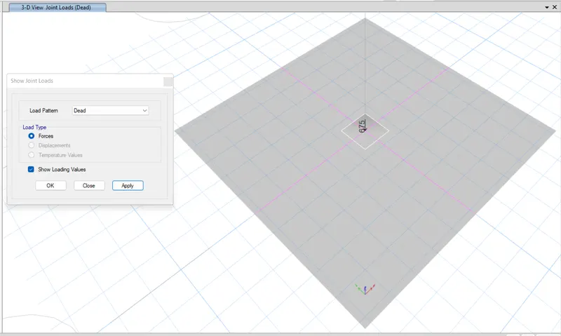
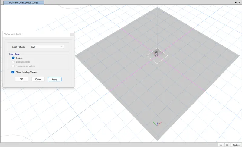
- However, we need to check if the loads are appropriately located or not.
- And for this, go to display>show loads assigned>dead/live>ok.
Dead Load
Live Load
- Define and Assign Soil Spring
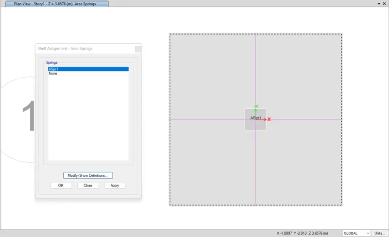
- Spring constant for soil is given by the formula: Factor of safety x soil bearing capacity / allowable settlement.
- So, calculate the same based on your soil report then define the same from define>soil properties.
- Then, select the footing>go to assign>area spring>spring1>ok.
- The procedure for the same is shown below:
- Run the Analysis and Design
- After assigning the load patterns and the soil spring, our model is set to be run for analysis.
- Also, unlike ETABS, safe runs the analysis and designs the section for you at the same time.
- However, there are a few checks you need to make once the analysis and design are completed and the same is discussed in the below sections.
- Check for Settlement
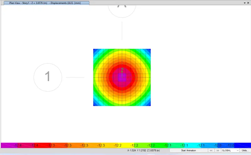
- The first thing we need to observe is the total footing slab settlement measured in mm.
- And to do so, go to display>show deformed shape>SLS load combo>ok.
- SAFE will show you the total displacement in mm due to the said load combination.
- And it should be within the limits specified by the codes.
- So, for isolated footings, 25mm of maximum displacement is allowed as per the codebook.
- And the settlement in case of our footing is inserted below that is way less than the said limit. Hence OK.
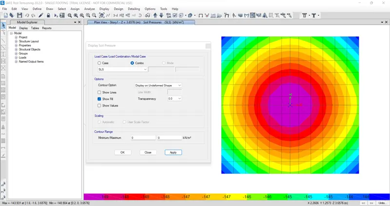
- Check for Soil Pressure
- Now we need to see if the soil pressure due to the service load combination is within the range of soil bearing capacity as received from the soil report.
- And to do that, go to display>soil pressure>SLS load combo>ok.
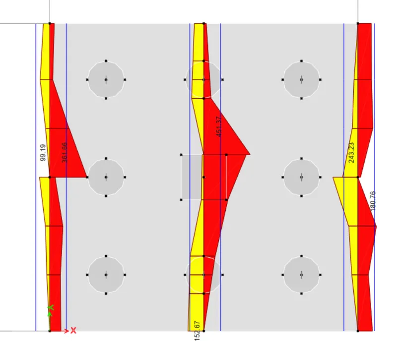
- The same is shown below which in our case is 149 KN/sq.m < 150KN/sq.m. Hence OK.
- Run the Analysis and Design
- Now that all things are set, we can run the analysis and design by clicking on the play button from the top tool ribbon in SAFE.
- The analysis will get completed within a few seconds and we will need to execute several checks as we did in the case of the isolated footings.
- So, the procedure shall be exactly the same and you can refer to the isolated footing section for a more detailed procedure.
- Here, we have included the final results of the design check as follows:
- Check for Settlement
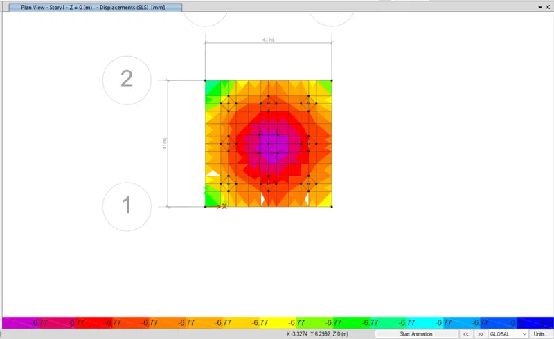
- Maximum displacement (6.77mm) is way lesser than the permissible value stated by the codes (25mm). Hence, OK.
- Punching Shear Check
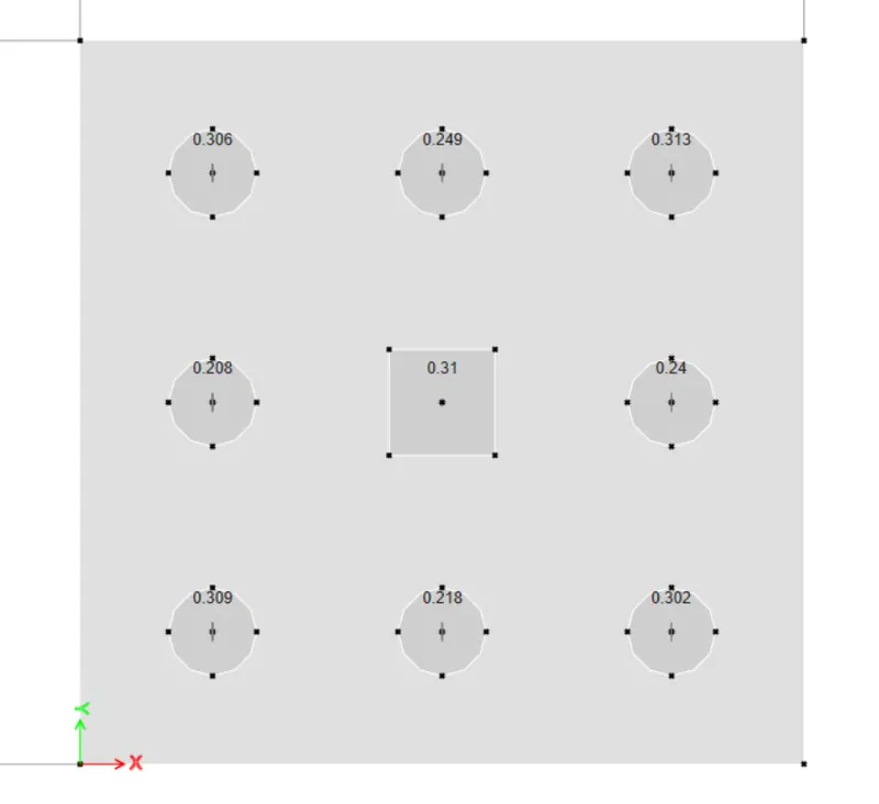
- Allowable punching shear value is equal to unity. Hence, OK.
- Base Reactions at Piles
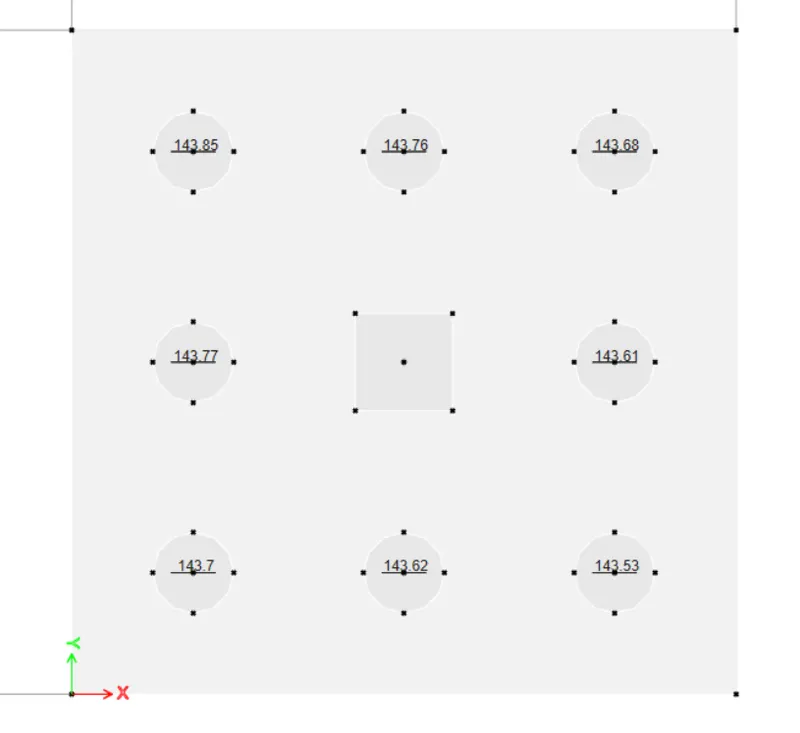
- Our pile bearing capacity is 200KN. Hence, OK.
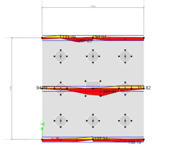
- Longitudinal Reinforcement Requirement
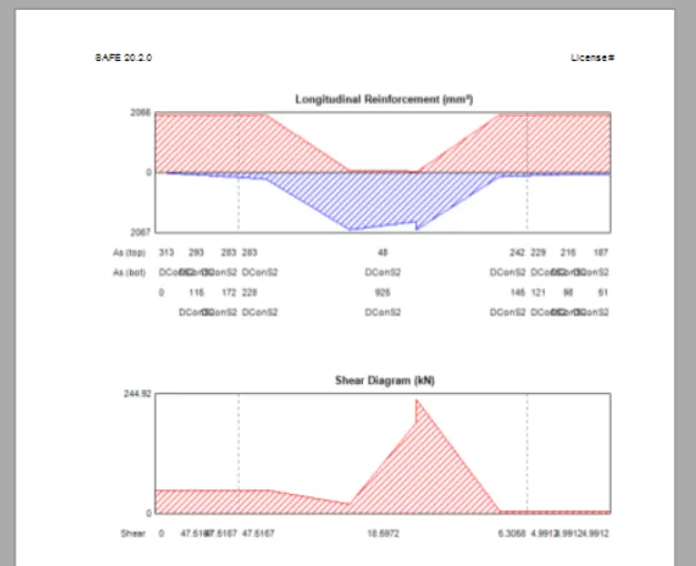
Maximum Rebar Area for Design Strip A
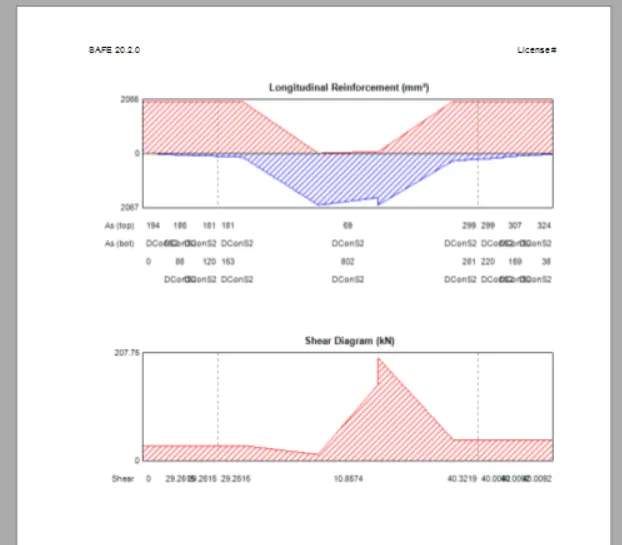
Maximum Rebar Area for Design Strip B