Foundation Design using SAFE
1. Model the isolated footing provided in week 11 challenge on SAFE. Analyze and design it to verify the size, depth and steel provided as per calculations.
Aim
To determine the isolated footing on SAFE. Analyze and design it to verify the size, depth and steel provided as per calculations.
Introduction:
Square footing for a column sixe of 400x400
compression axial load for the load combination of (1.5 DL = 1.5 LL) is 2000kn
The safe soil bearing capacity is 150 Kn/m2 at depth of 2m
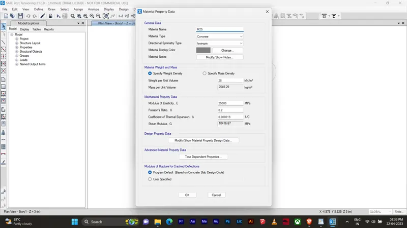
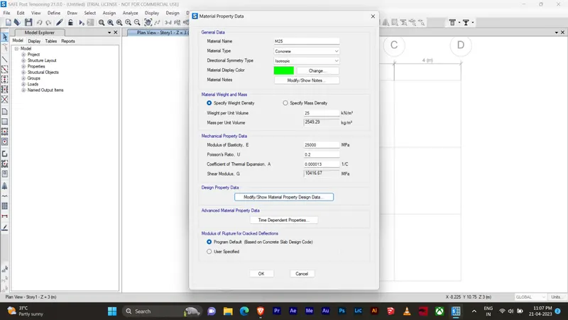
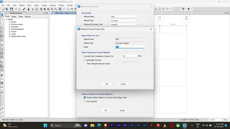
Assuming M25 concrete grade
Procedure
Data required for safe analysis & design
Unfactored load = 2000/1.5 = 1333.3Kn
Dead load breakup = 1333.3/2 = 666.7 Kn
Live load breakup = 1333.3/2 = 666.7 Kn
Subgarde modulus for soil = safe bearing capacity x factor to ultimate /maximum settelement
=150 x 3 / 0.05 = K = 9000Kn/m3
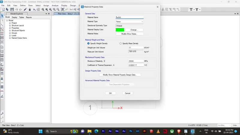
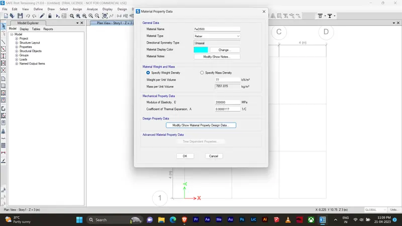
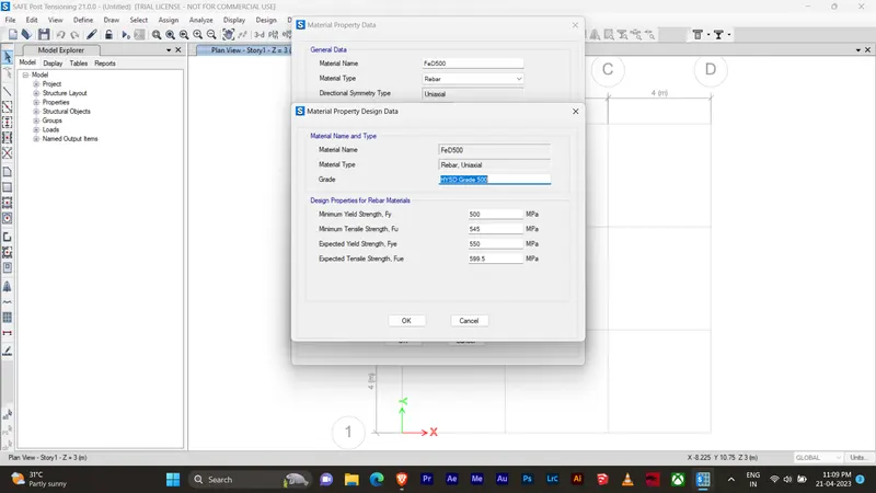
Rebar yeild strength (fy) = 500 N/mm2
Rebar ultimate strength (fu) = say 575 N/mm2
Elastic modulus of M25concrete = 25000N/mm2
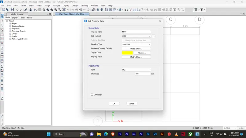
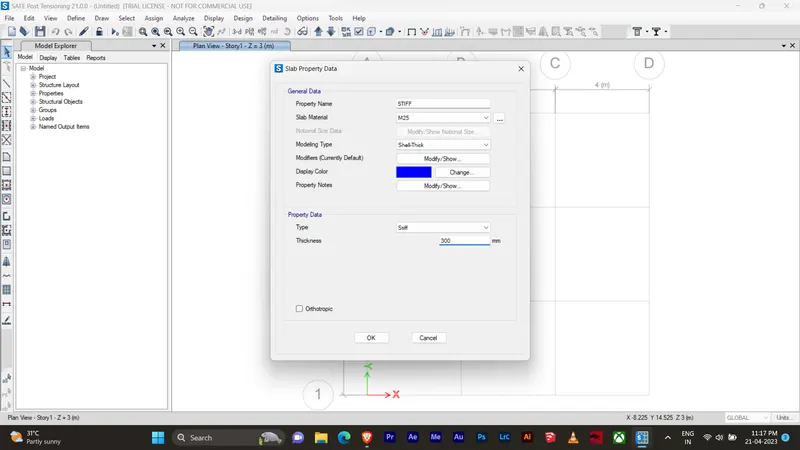
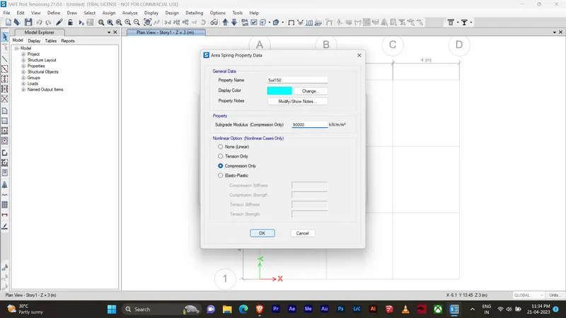
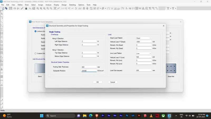
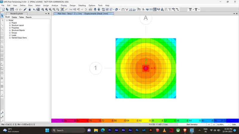
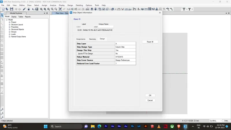
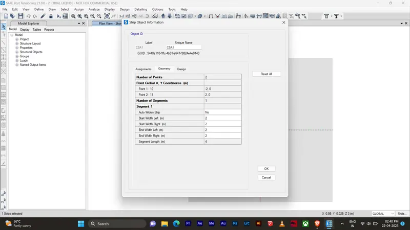
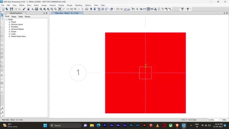
Check Need to be performed in SAFE analysis
1. Safe bearing capacity under service load.
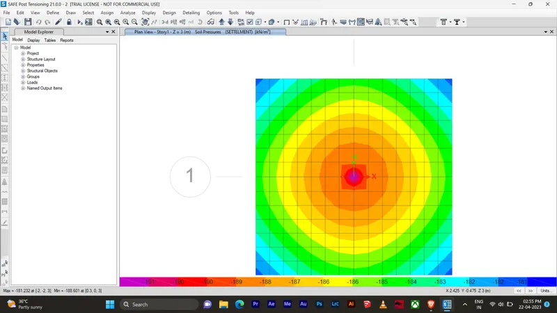
2. Settelment under service load.
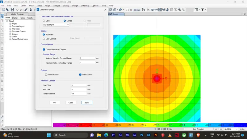
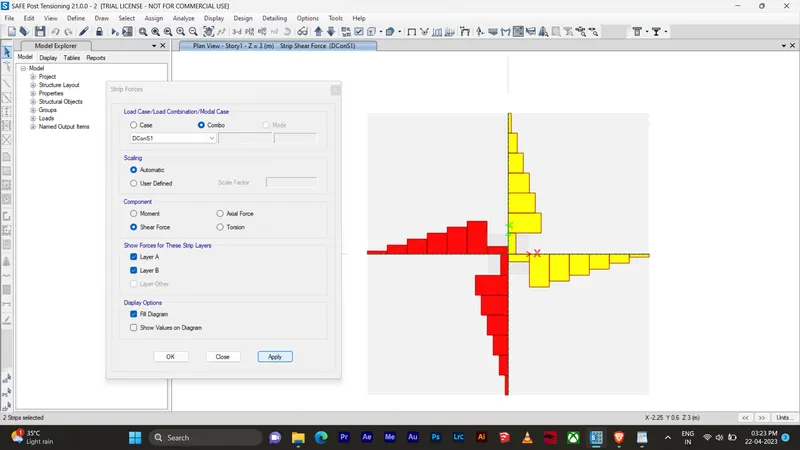
3. Two way shear check (punching shear).
IS 456:2000 Punching Shear Check & Design
Geometric Properties
Combination = DConS2
Story = Story1
Point Label = 9
Column Shape = Rectangular
Column Location = Interior
Global X-Coordinate = 0 m
Global Y-Coordinate = 0 m
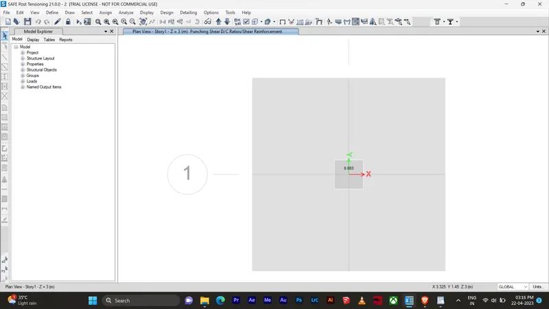
Load Punching Check
Avg. Eff. Slab Thickness = 567 mm
Eff. Punching Perimeter = 4668 mm
Cover = 33 mm
Conc. Comp. Strength = 30 MPa
Reinforcement Ratio = 0
Section Inertia I22 = 63621893.6 cm⁴
Section Inertia I33 = 63621893.6 cm⁴
Section Inertia I23 = 0 cm⁴
Gammav2 = 0.4
Gammav3 = 0.4
Moment Mu2 = 2.342E-06 kN-m
Moment Mu3= -2.343E-06 kN-m
Shear Force = -3200.8756 kN
Unbalanced Moment Mu2 = 9.367E-07 kN-m
Unbalanced Moment Mu3= -9.373E-07 kN-m
Max Design Shear Stress = 1.21 MPa
Conc. Shear Stress Capacity = 1.37 MPa
Punching Shear Ratio = 0.88
4. Ultimate bearing moment.
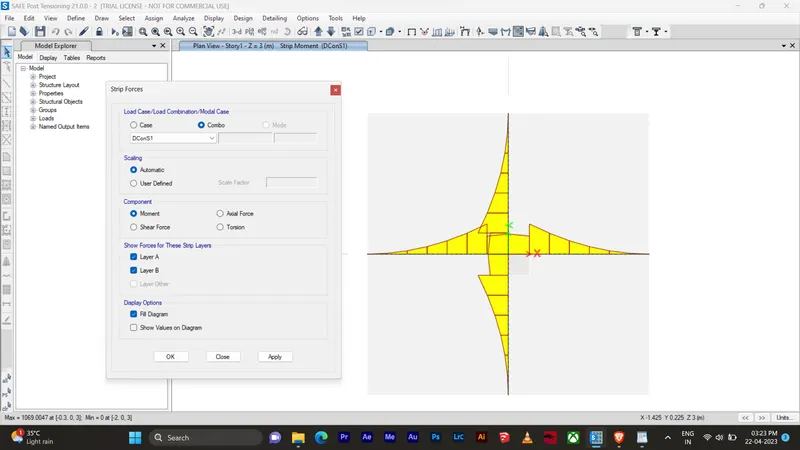
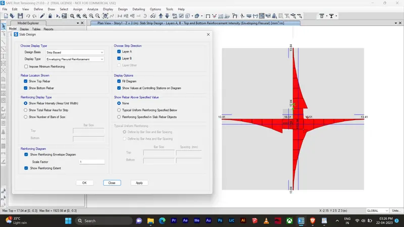
5. Flexural reinforcemnt design for footing slab.
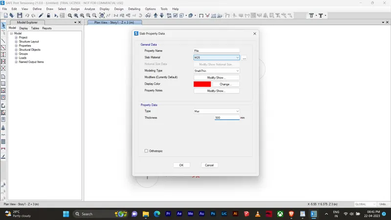
2. A column of size 600x600 carrying an unfactored gravity load (DL+LL) of 1175 KN is to be supported on pile cap, which ultimately transfers load to the piles underneath. Piles of 16 metres length and 500 mm diameter are to be used. Each pile has a load carrying capacity of 200 KN. Model, analyse and design the pile cap on SAFE to evaluate the following:
- Pile group to be used
- Depth of pile cap
- Longitudinal steel on top and bottom face in both directions
Aim:
To determine column of size 600x600 carrying an unfactored gravity load (DL+LL) of 1175 KN is to be supported on pile cap which ultimately transfers load to the piles underneath.
Introduction
- A column of size 600x600 carrying an unfactored gravity load (DL+LL) of 1175 KN is to be supported on pile cap, which ultimately transfers load to the piles underneath.
- Piles of 16 metres length and 500 mm diameter are to be used. Each pile has a load carrying capacity of 200 KN.
- Refered IS 2911 (part 2) and SP 34
Procedure:
Data required for safe analysis & design
Unfactored load = 1175Kn
Dead load breakup = 1175/2 = 587.5 Kn
Live load breakup = 1175/2 = 587.5 Kn
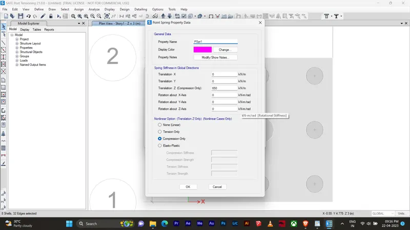
Point spring of pile = A x E x L
= 196349 x 25000 / 16000 = 306796 Kn/m
K is SAFE analysis = 306.8Kn/m3
Rebar yeild strength (fy) = 500 N/mm2
Rebar ultimate strength (fu) = say 575 N/mm2
Elastic modulus of M25concrete = 25000N/mm2
Number of piles required = unfactored load with self weight addition / individual file capacity
= 1175 x 1.1/200 = 6.5
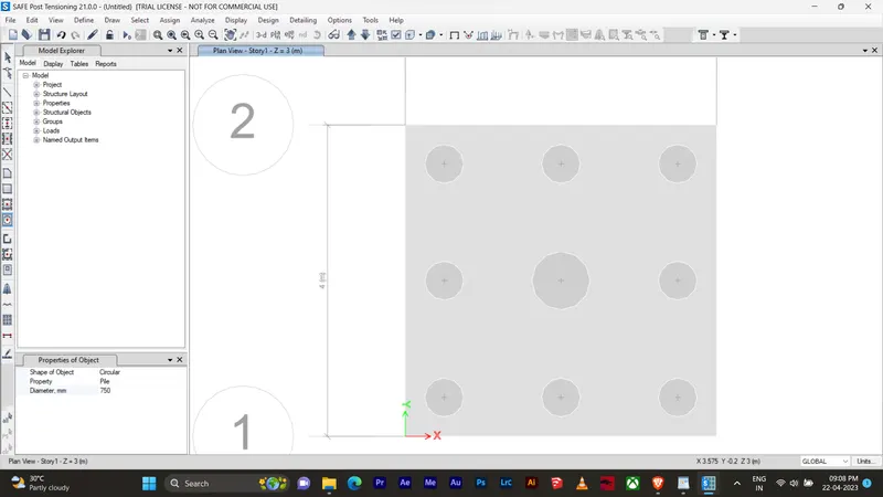
consider 8 files for symmetric placement of pile and pile cap
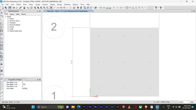
Take centre to centre distance between piles = 3 x pile diameter (1500 mm)
Edge distance from pile centre = one next pile diameter (500 mm)
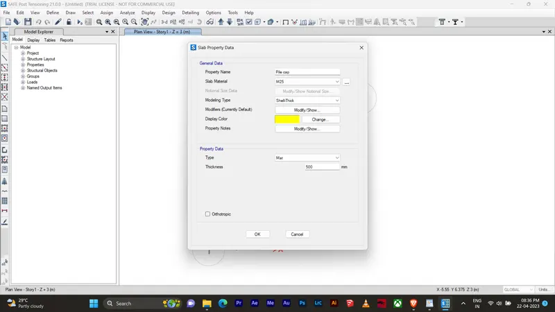
Assumed pile cap depth = 500 mm