Foundation Design using SAFE
question 1
AIM - Model the isolated footing, Analyze and design it to verify the size, depth and steel provided as per calculations.
- Square rooting for a column size of 400x400
- compress on axial load for the load combination of 1.5 DL+ 1.5 LL is 2000 KN
-
The safe Soil bearing capacity is 150 KN/m2 at a depth of 2 metres below E.G.L
Assume 25 concrete grade
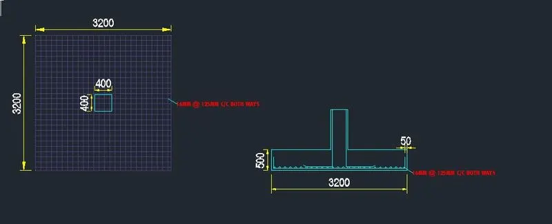
Data required for SAFE analysis & Design
- Unfactored load = 2000/1.5= 1333.3 KN
- Dead load breakup = 1333.3/2=666.7 kN Live load breakup = 1333.3/2=666.7 kN
- Subgrade modulus for soil = Safe bearing capacity x factor to Ultimate / maximum settlement 150 x 3/0.05= k = 9000 kN/m3
- Rebar yield strength (Fy) = 500 N/mm2
- Rebar ultimate strength (Fu) = Say 575 N/mm2
- Elastic modulus of M25 concrete = 25000 N/mm2
DESIGN PROCEDURE USING ETABS
- First we need to selected isolated footing assign material like M25 and FE500 for conc and steel respectively
- Then we have to assign those properties and add load combinations of service limit state and ultimate limit state
- We should assign design strips for r/f details
RUN THE ANALYSIS
CHECK AFTER THE ANALYSIS
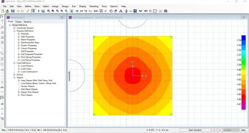
- Safe bearing capacity under service load
The safe bearing capacity is 150kn/m3 here we are getting less than that hence safe
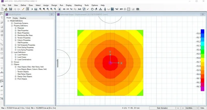
- Settlement under service load
The max allowable deflection is 50mm we are getting deflection upto 16mm hence safe
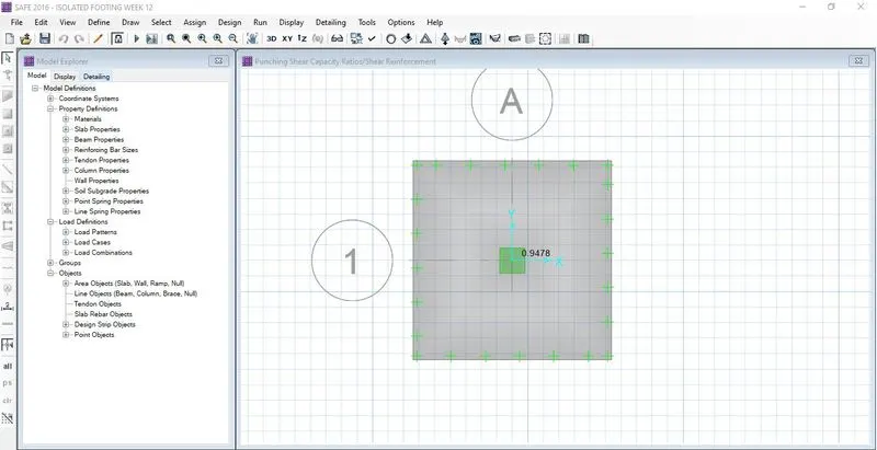
- punching shear check
section passed in 2 way shear check.
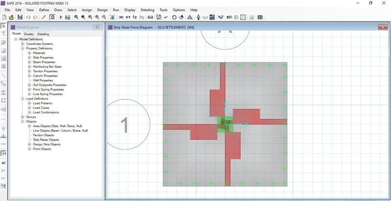
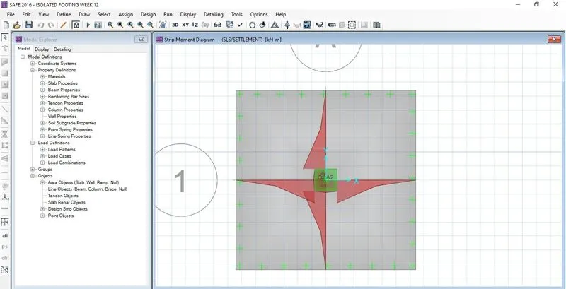
- Shear force and bending moment
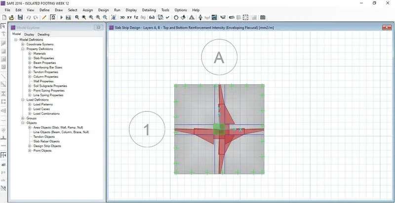
- Flexural Reinforcement of design
QUESTION 2
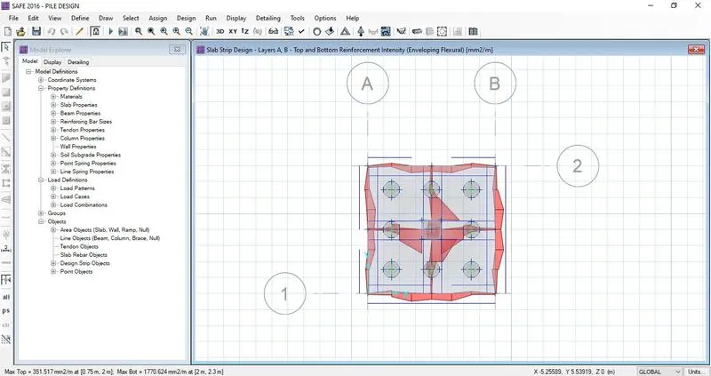
AIM - Model, analyse and design the pile cap on SAFE to evaluate the following:
- Pile group to be used
- Depth of pile cap
- Longitudinal steel on top and bottom face in both directions
Data required for SAFE analysis & Design
-
Number of piles required - Unfactored load with self weight addition/ individual pile capacity= 1175 x 1.1/200=6.5
- Consider 8 piles for symmetric placement of piles under pile cap
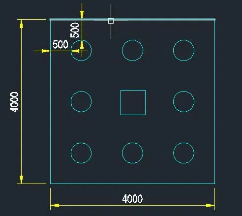
- Take center to center distance between piles = 3 x pile diameter (1500 mm) Edge distance from pile center = 1 x pile diameter (500 mm)
- Assumed pile cap depth = 500 mm
Tentative pile arrangement
where center is columns sorrounded by piles 8 nos
- DESIGN CALCULATIONS
Unfactored load = 1175 kN
Dood load breakup = 1175/2 = 587.5 kN
Live load breakup = 1175/2 = 587.5 kN
Point spring of Pile = A x E/L = 196349 x 25000/16000 = 306796 kN/m
k for SAFE analysis = 306.8 kN/mm
Rebar yield strength (Fy) = 500 N/mm2
Rebar ultimate strength (Fu) = Say 575 N/mm2
Elastic modulus of M25 concrete = 25000 N/mm2
DESIGN PROCEDURE USING ETABS
- First we need use grid for the plan and assign material like M25 and FE500 for conc and steel respectively
- Then we have to assign pilecaps, piles and columns in the data, also add the point where we can add those pile caps, using add point in draw command.
- using add pile cap we can add those pilecaps and then later after selecting the points we can assign spring to those points from assign menu
- we should add design strips and load combos for SLS
- Select all piles individually and change steel to FE500 and check design preferences
RUN THE ANALYSIS
CHECK AFTER THE ANALYSIS
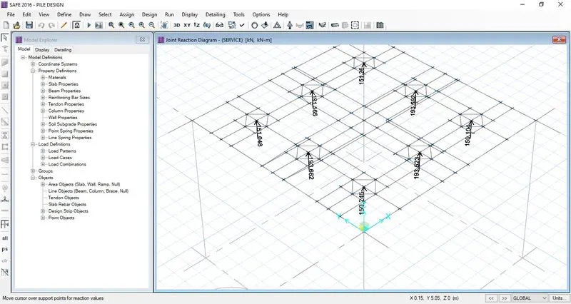
- individual pile capacity under service load
We can the pile sharing the point reaction is less then 200kn hence safe
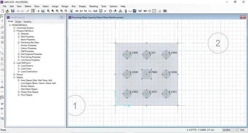
- Punching shear check
passed in punching shear
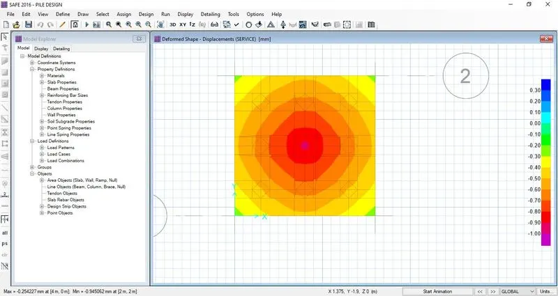
- Settlement under service load
The max deflection is less than 1mm hence safe
- Flexural Reinforcement of design