Foundation Design using SAFE
AIM :
To Model the isolated footing provided in week 11 challenge on SAFE. Analyze and design it to verify the size, depth and steel provided as per calculations.
INTRODUCTION :
Foundation design is the creation of a construction plan for a building foundation. It is a highly specialized function and usually performed by a structural engineer. The foundation is the structural base that stands on the ground and supports the rest of the building. Therefore, foundation design must involve extensive study of the ground below the foundation as well as the design and materials used on the foundation itself.
Foundations must be designed so that loads imposed by the building are transferred uniformly to the contact surface to transmit the sum of the dead load, live load, and wind load to the ground. The net loading capacity coming into the soil should not exceed the bearing capacity of the soil. Foundation design also must take into account expected settling from the building to ensure that all movement is controlled and uniform to prevent damage to the structure. In addition, the overall design of the foundation, superstructure, and characteristics of the ground should be studied to identify potentially beneficial construction strategies.
Foundations typically are built with masonry, such as concrete block or brick, or with poured concrete. Masonry materials offer high compressive strength and are much more resistant to damage from moisture and soil than wood and metal materials. A masonry foundation typically extends above the ground to protect other building materials from moisture and other damaging effects of ground contact. Masonry foundations usually are reinforced internally with metal rebar or other materials. Contractors will often use hydraulic cement to seal around pipes or raceways that penetrate the masonry or concrete foundation.
PROCEDURE :
STEP :1
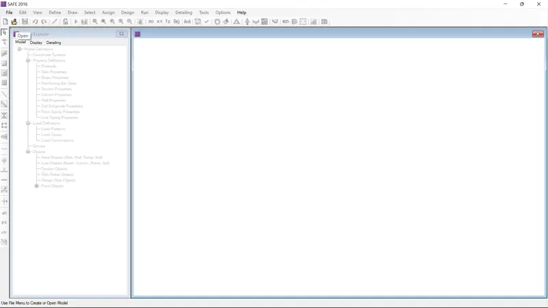
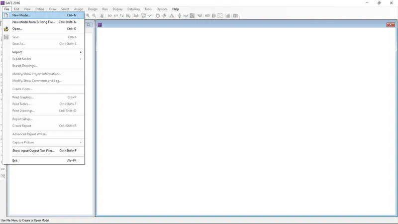
- Open the new safe file model
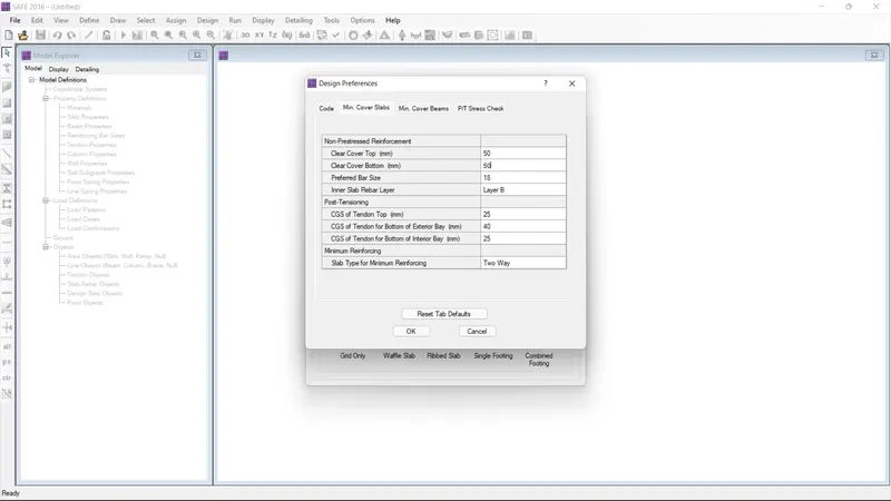
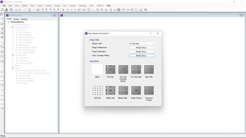
- After clicking the new model the define preference dialouge box as been open
- Give the both cover as 50 mm
- Give the prefered bar size as 18 and then click ok
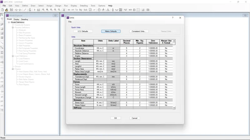
- After modify the units
- Give the units as metric default and then click ok
- And then select the single footing
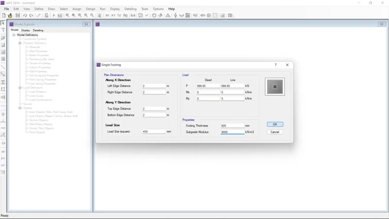
- Give the all direction as 2 and load size as 400
- And then load P as 666.65 for both
- Give the footing thickness as 800 and soil sungrade as 9000
- And then click ok
=> Subdrade soil = FOSXSBC/Settlement
=> Safe bearing capacity = 150 Kn/m2
=> FOS = 3, Settlement = 50mm
=> Subgrade modylus = 3x150/0.05 = 9000 Kn/m2
=> The compression axial load for the load combination of (1.5DL + 1.5LL) is 2000 KN
=> Unfactored load = 2000/1.5 = 1333.33 KN
= 1333.33/2 = 666.65 KN
=> Square footing for column of 400 x 400
=> Thickness of concrete footing as = 0.8m
STEP :2
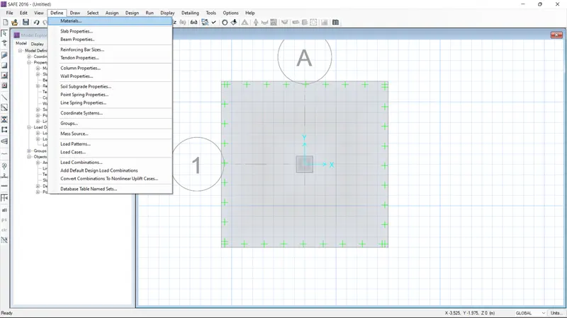
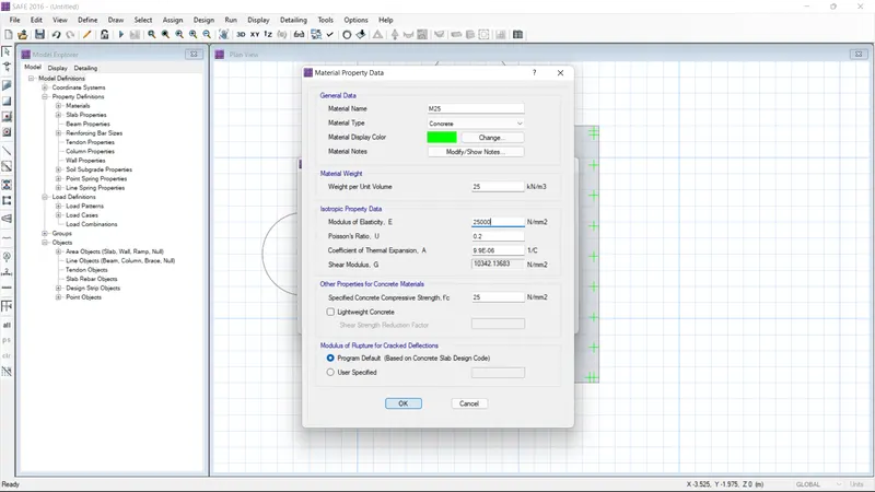
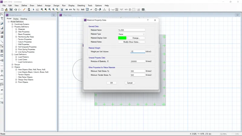
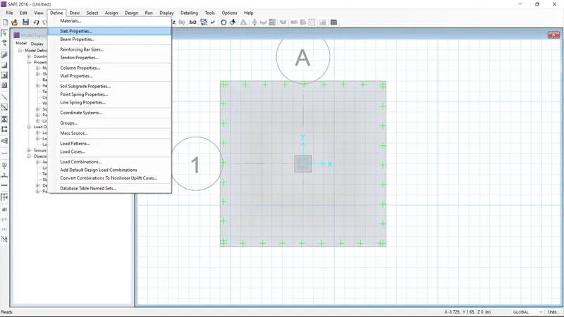
- Go the define option and select the material properties
- give the name Fe500 and set material type as rebar
- The value of material weight as 77
- The uniaxial data value as 200000
- Give the other properties of material values are 500 and 545
- And then click ok
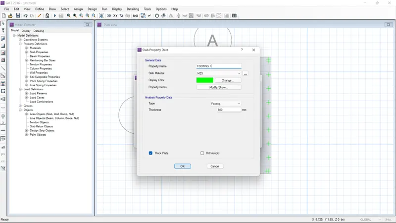
- Go to the slab properties data
- And give the propertie name as footing
- give the slab material as M25
- Select Type as footing and thickness as 800
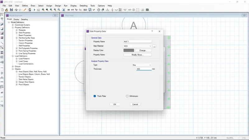
- Again go the slab properties data
- And give the propertie name as Mat1
- give the slab material as M25
- Select Type as MAT and thickness as 300
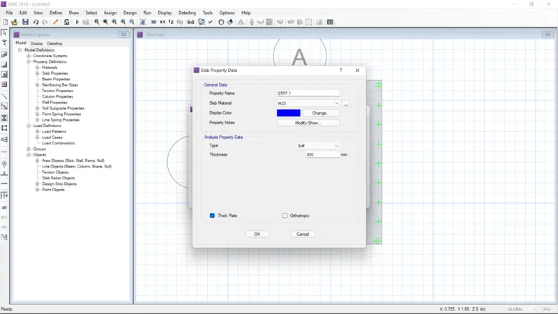
- Again go the slab properties data
- And give the propertie name as Stiff1
- give the slab material as M25
- Select Type as stiff and thickness as 800
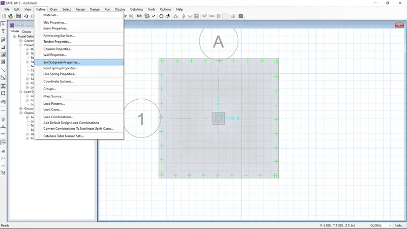
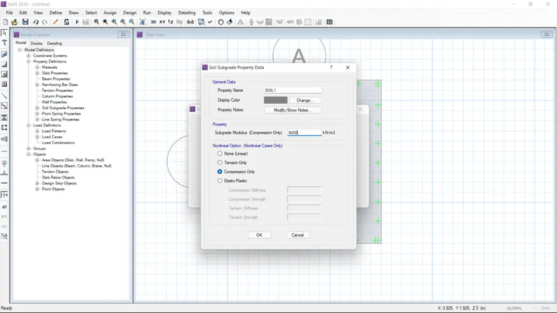
- Next go the soil subgrade properties
- And create the new data
- the name as soil 150
- And soil modulus as 18000
- And then click ok
STEP :3
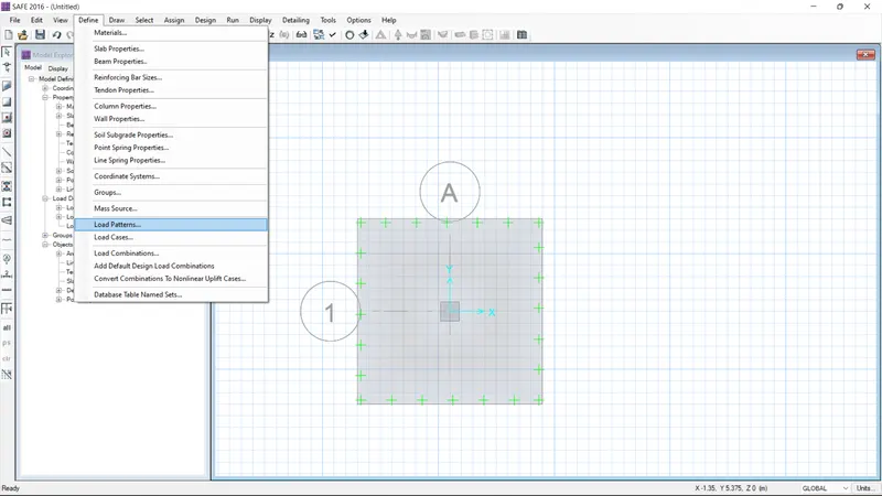
- Go to the defien load pattern
- Give the dead and live load
- right click the footing and the " the slab type area object information " dialouge box as been opened
- And set the slab properties and soil properties
- right click the Stiff and the " the slab type area object information " dialouge box as been opened
- And set the slab properties and soil properties
- Set the loads and load combination
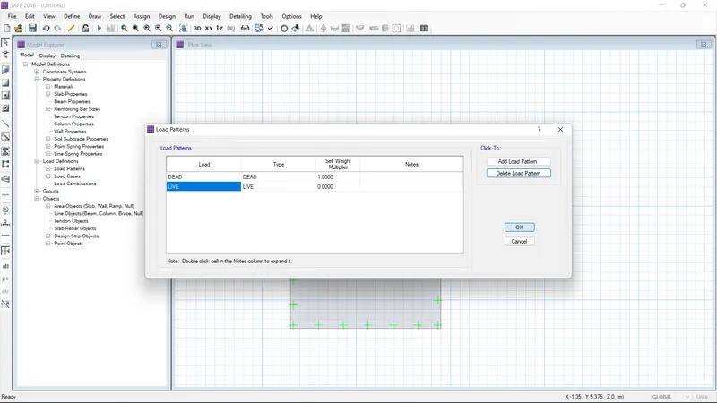
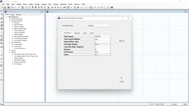
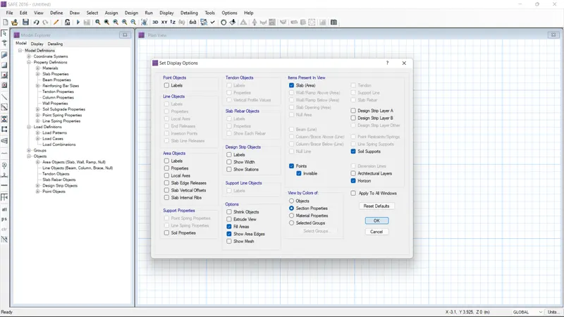
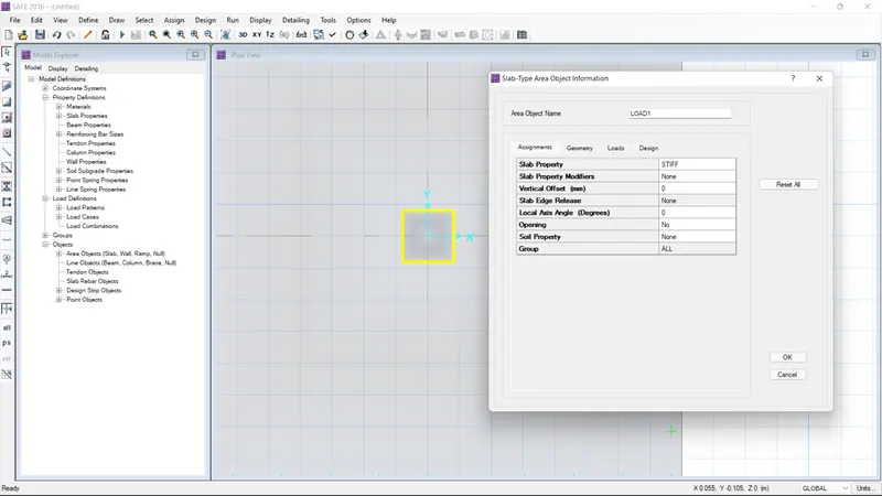
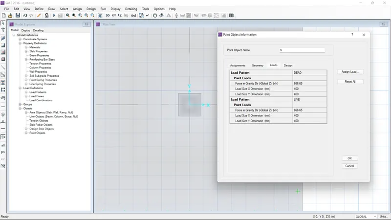
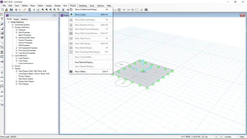
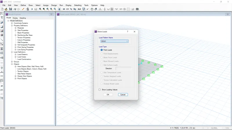
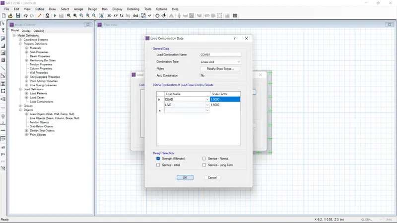
STEP :4
- Give the run alaysis option
- After complete the analysis
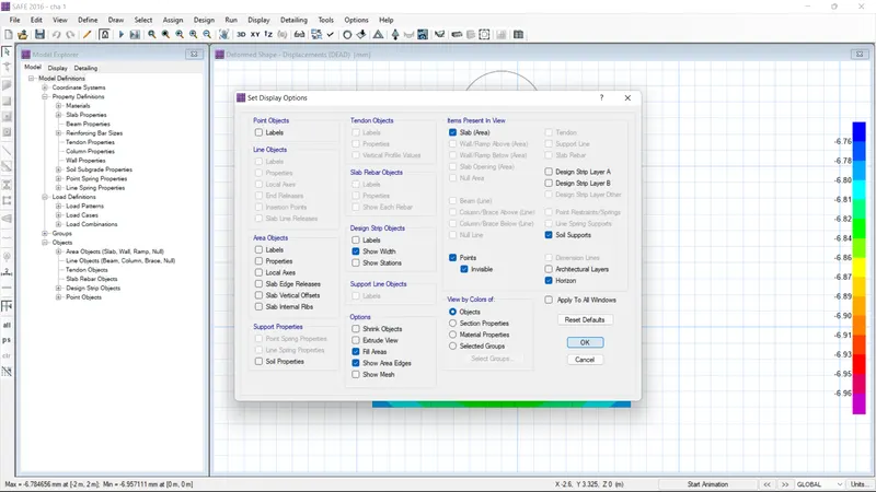
- Go the set display option select the show width option
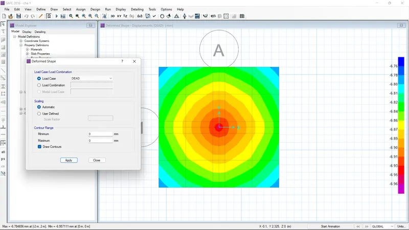
- Go the deformed shape option and then click ok and check it
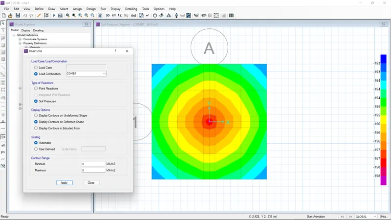
- Go the reaction option and then click ok and check it
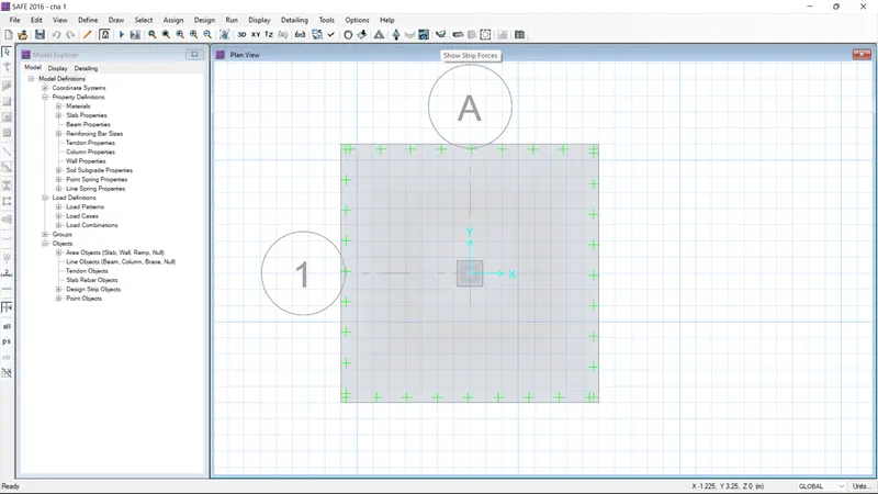
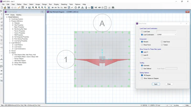
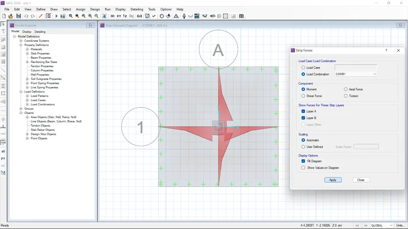
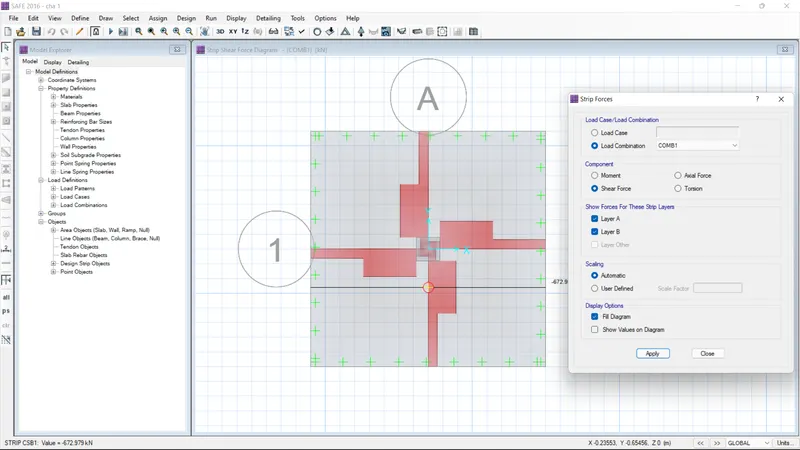
- Select the show strip option, give the load combination and then apply and see the reaction
- check the moment and shear force
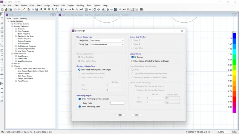
- And go the show slab design
- And select the layer A and B and then click ok
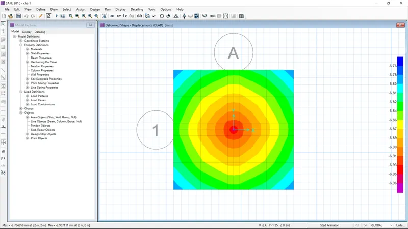
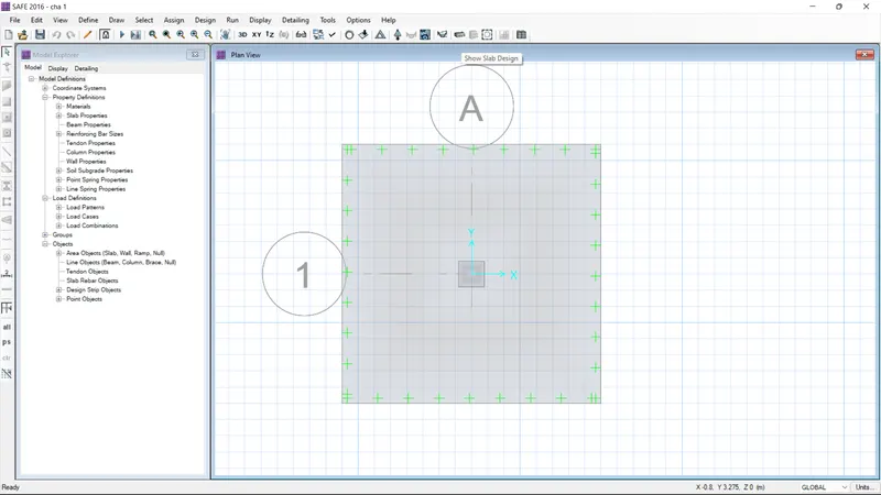
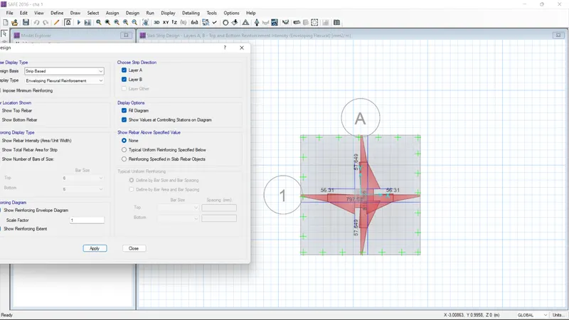
RESULT:
As per the question 1 the model as designed and analysis with using safe software
2. A column of size 600x600 carrying an unfactored gravity load (DL+LL) of 1175 KN is to be supported on pile cap, which ultimately transfers load to the piles underneath. Piles of 16 metres length and 500 mm diameter are to be used. Each pile has a load carrying capacity of 200 KN. Model, analyse and design the pile cap on SAFE to evaluate the following:
- Pile group to be used
- Depth of pile cap
- Longitudinal steel on top and bottom face in both directions
AIM :
To design column of size 600x600 carrying an unfactored gravity load (DL+LL) of 1175 KN is to be supported on pile cap, which ultimately transfers load to the piles underneath. Piles of 16 metres length and 500 mm diameter are to be used. Each pile has a load carrying capacity of 200 KN. Model, analyse and design the pile cap on SAFE to evaluate the following
INTRODUCTION :
Foundations must be designed so that loads imposed by the building are transferred uniformly to the contact surface to transmit the sum of the dead load, live load, and wind load to the ground. The net loading capacity coming into the soil should not exceed the bearing capacity of the soil. Foundation design also must take into account expected settling from the building to ensure that all movement is controlled and uniform to prevent damage to the structure. In addition, the overall design of the foundation, superstructure, and characteristics of the ground should be studied to identify potentially beneficial construction strategies.
Foundations typically are built with masonry, such as concrete block or brick, or with poured concrete. Masonry materials offer high compressive strength and are much more resistant to damage from moisture and soil than wood and metal materials. A masonry foundation typically extends above the ground to protect other building materials from moisture and other damaging effects of ground contact. Masonry foundations usually are reinforced internally with metal rebar or other materials. Contractors will often use hydraulic cement to seal around pipes or raceways that penetrate the masonry or concrete foundation.
PROCEDURE :
STEP :1
- Open the new safe file model
- After clicking the new model
- set the design code as IS
- Modify the define preference dialouge box as been open
- Give the both cover as 50 mm
- Give the prefered bar size as 16 and then click ok
- After modify the units
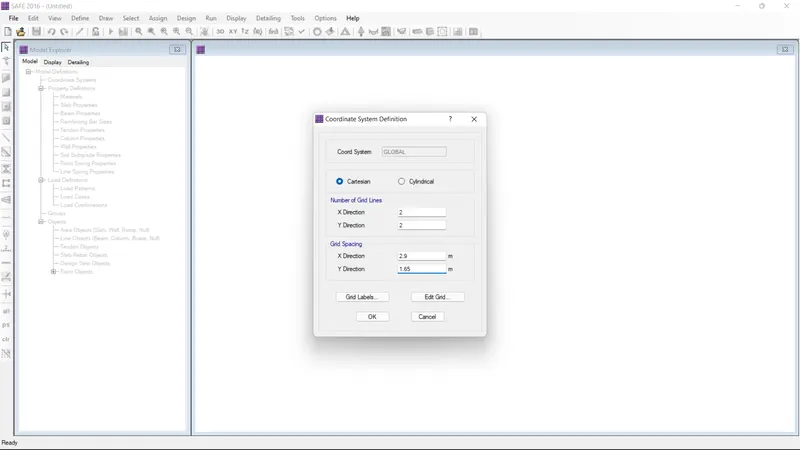
- Modify the coordinate system defintion
- x-direction as 2.9 and Y-direction as 1.65
- then click ok
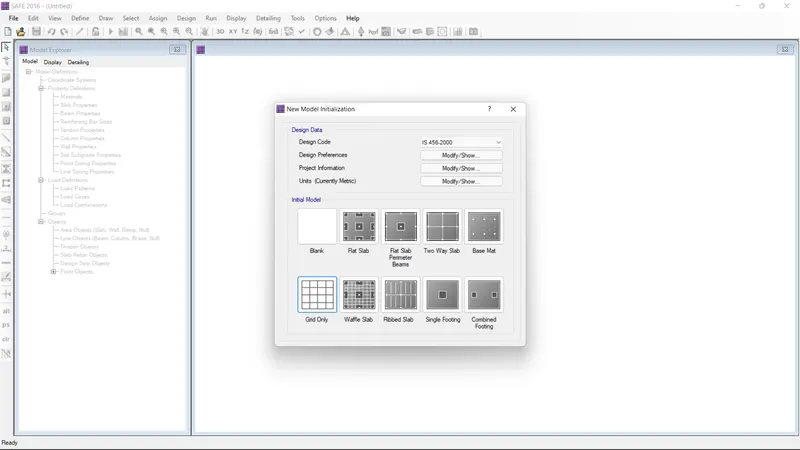
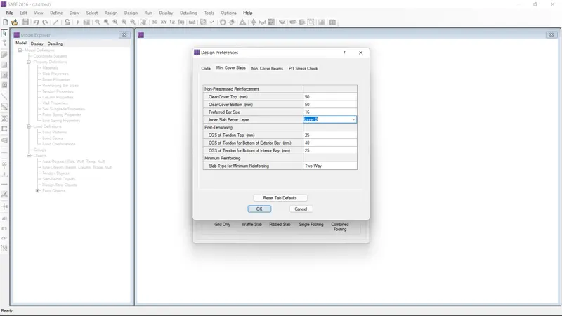
STEP :2
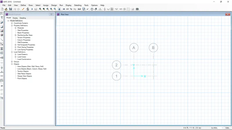
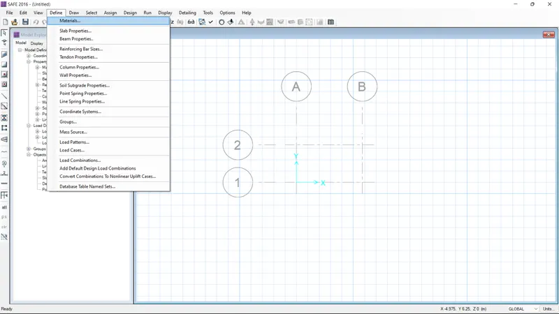
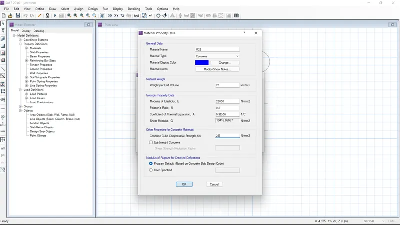
- Go the define option and select the material properties
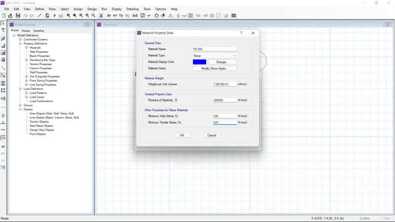
- give the name Fe500 and set material type as rebar
- The value of material weight as 77
- The uniaxial data value as 200000
- Give the other properties of material values are 500 and 545
- And then click ok
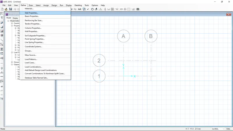
- Go to the slab properties data
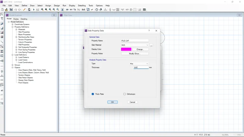
- And give the propertie name as pile cap
- give the slab material as M25
- Select Type as footing and thickness as 800
- Again go the slab properties data
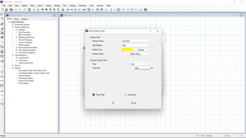
- And give the propertie name as column
- give the slab material as M25
- Select Type as MAT and thickness as 800
- Again go the slab properties data
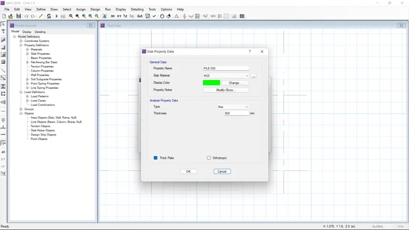
- And give the propertie name as pile 500
- give the slab material as M25
- Select Type as stiff and thickness as 800
STEP :3
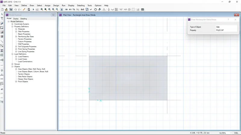
- Use the draw rectangle slab option
- Select the type of object slab and properties as pile cap
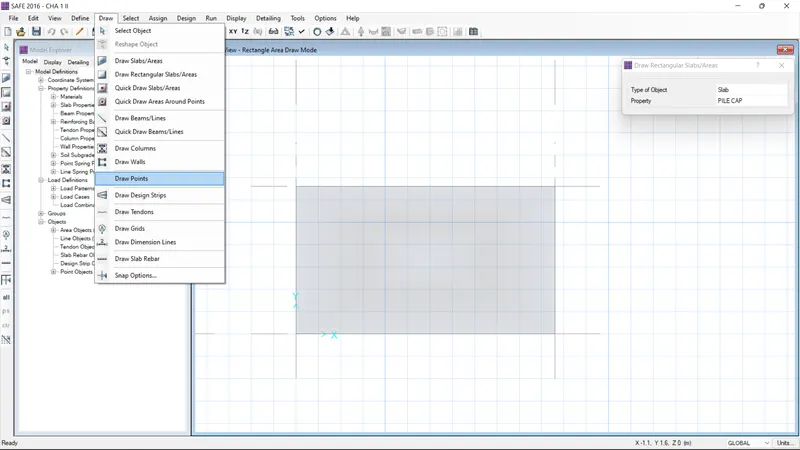
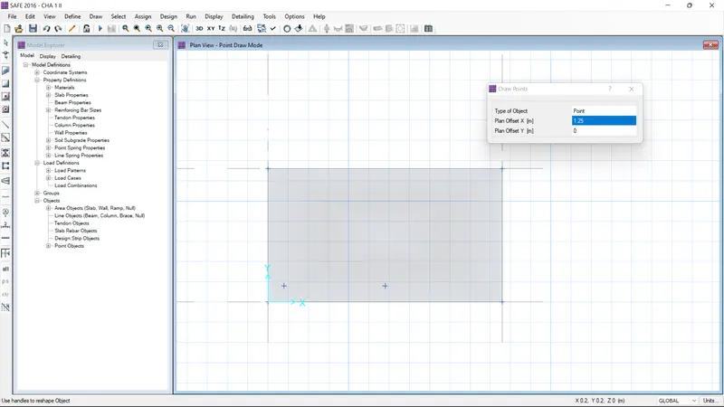
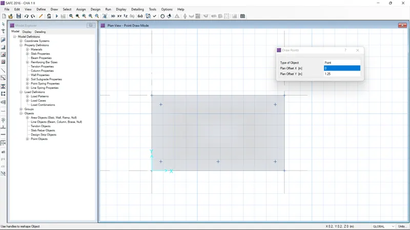
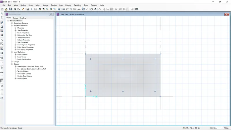
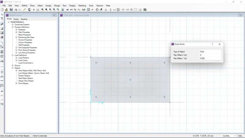
- Before the the slab first we want to create the points
- so select the draw option and select the draw points
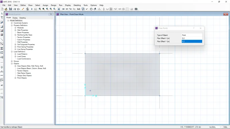
- first prefernce to X- 0.2 and Y- 0.2
- use the draw points and complete the points
STEP :4
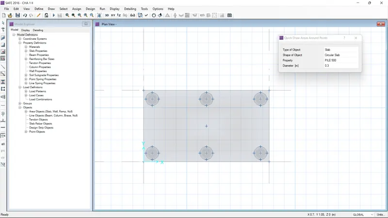
- After complete the points
- select the quick draw areas option
- And give the shape of object as "circular slab"
- And give the propertie as pile 500
- Then dia as 0.3
- place the pile as surrounding the points
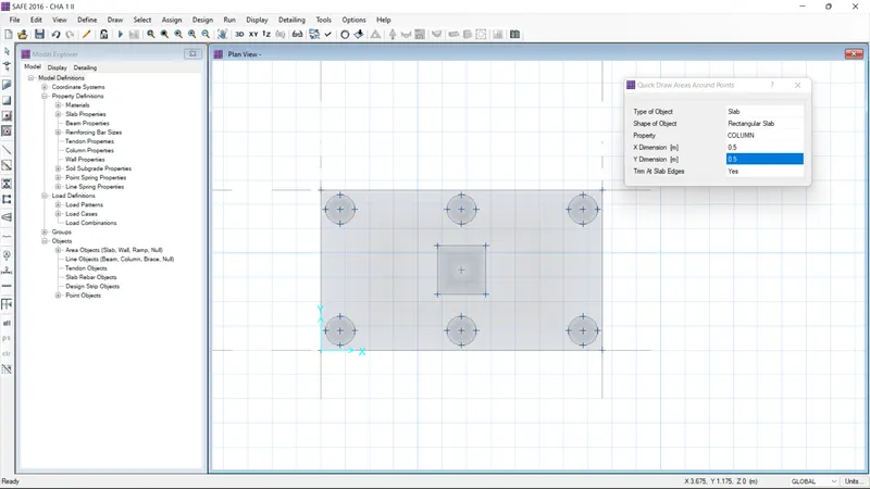
- the centre points as complete with rectangular slab
- And properties as column
- and x and y direction as 0.5
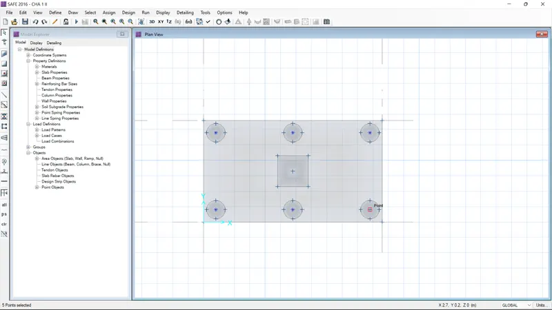
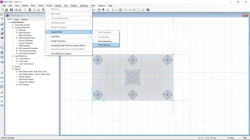
- AND assign the support data--> point spring to circular slab value as been = 306.79
- AND aasign the point load data to rectangular slab value as been = 587.5
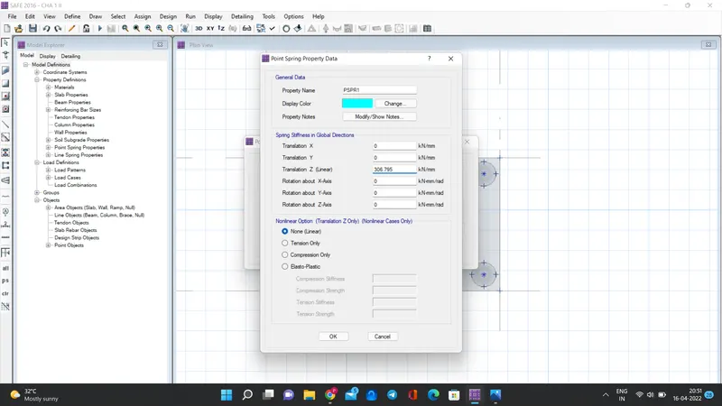
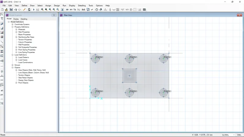
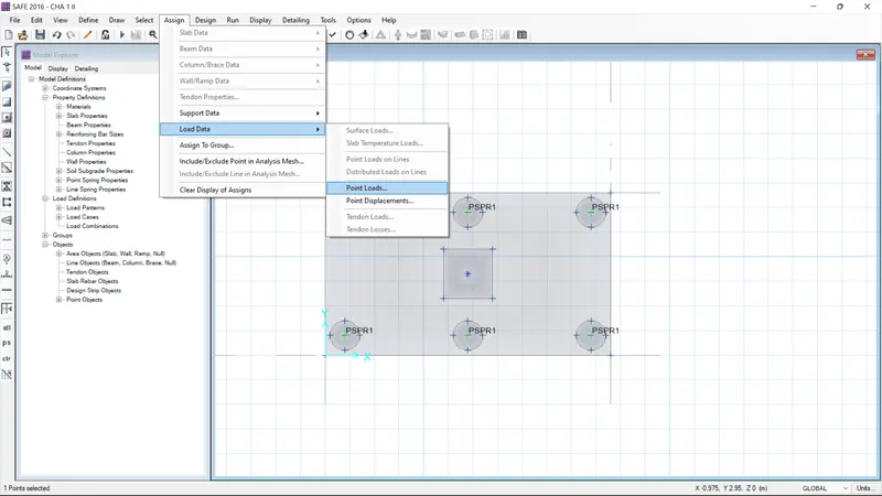
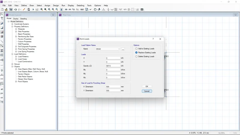
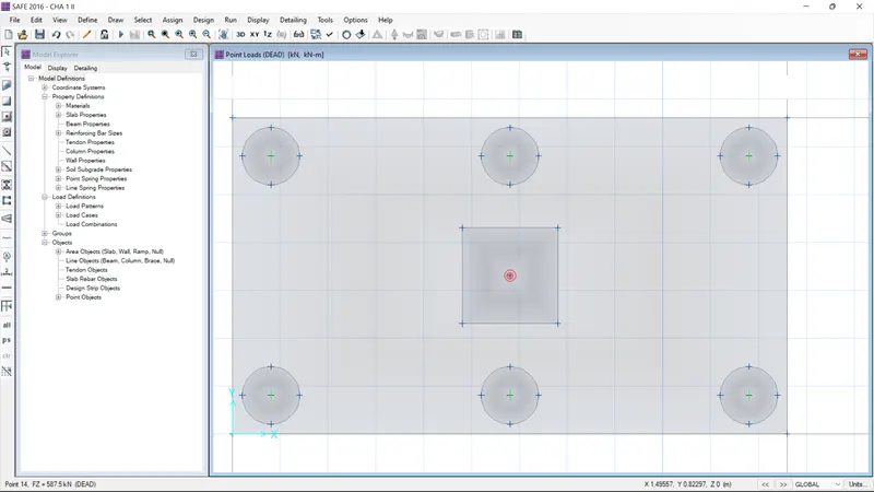
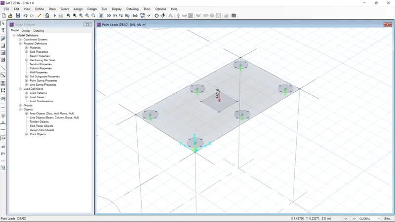
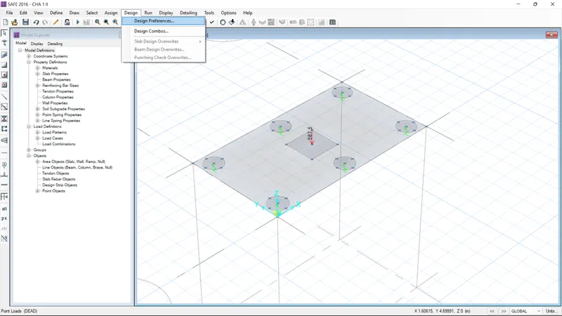
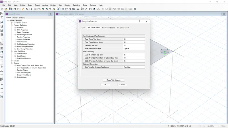
- Set the define preference as
- Give the both cover as 50 mm
- Give the prefered bar size as 18 and then click ok
STEP :5
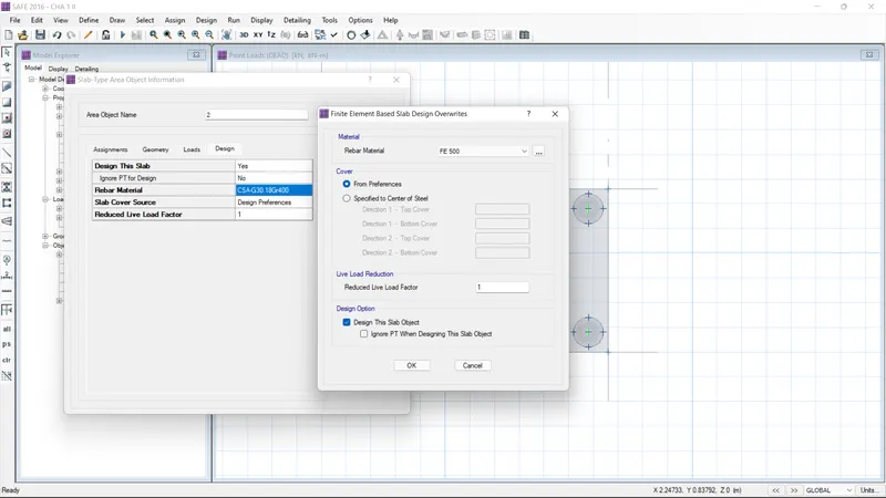
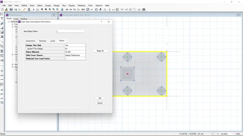
- Right click the slab and set the rebar material as fe500
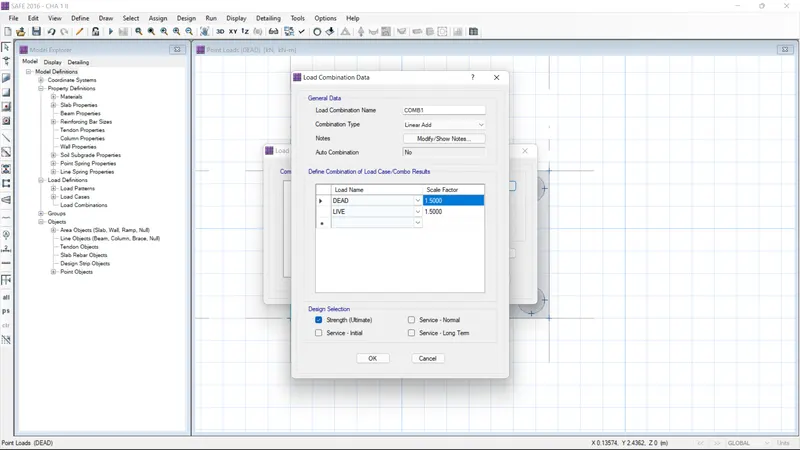
- Set the load combination
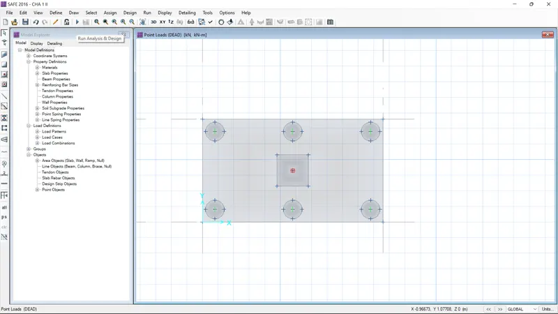
- finally analysis the model
STEP :6
- After complete the analysis
- Go the set display option select the show width option
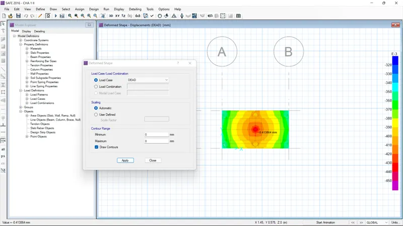
- Go the deformed shape option and then click ok and check it
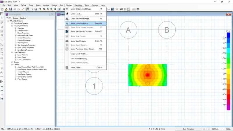
- Go the reaction option and then click ok and check it
- Select the show strip option, give the load combination and then apply and see the reaction
- check the moment and shear force
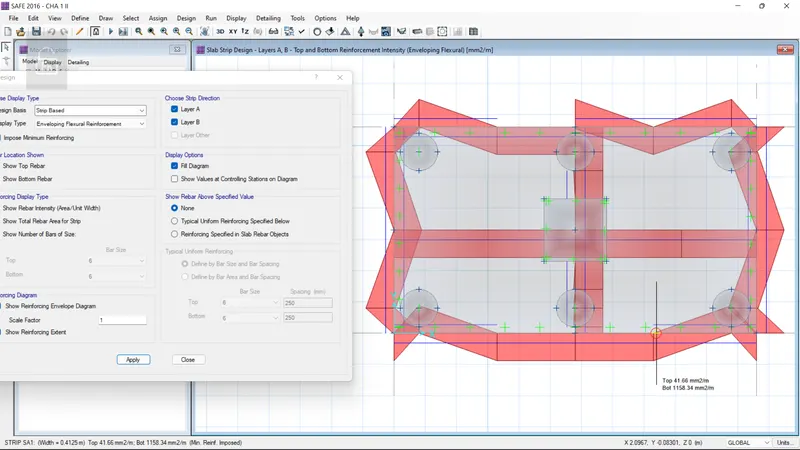
- And go the show slab design
- And select the layer A and B and then click ok
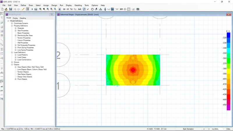
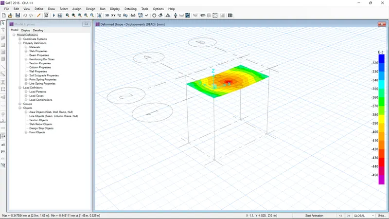
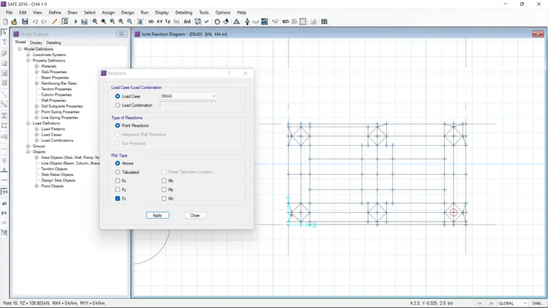
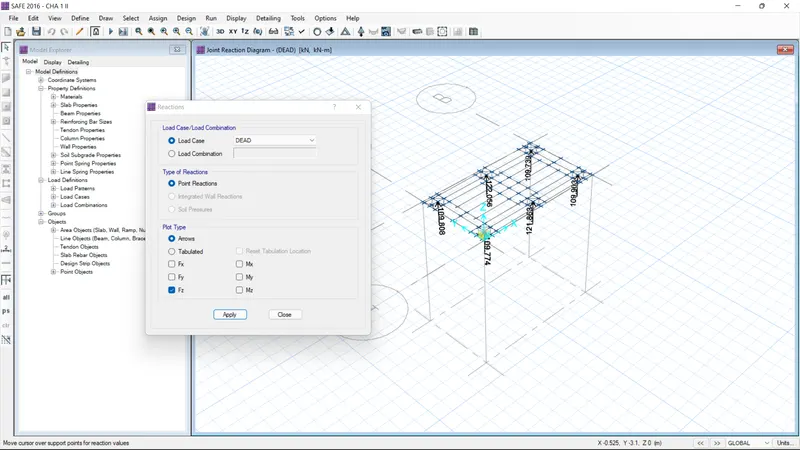
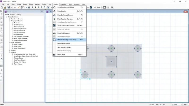
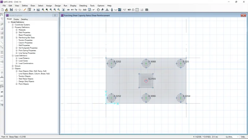
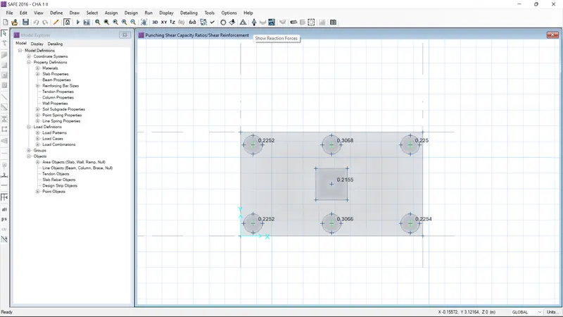
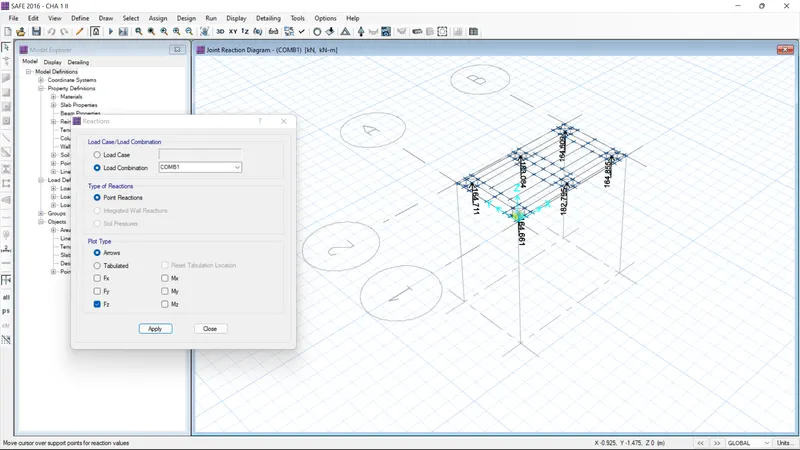
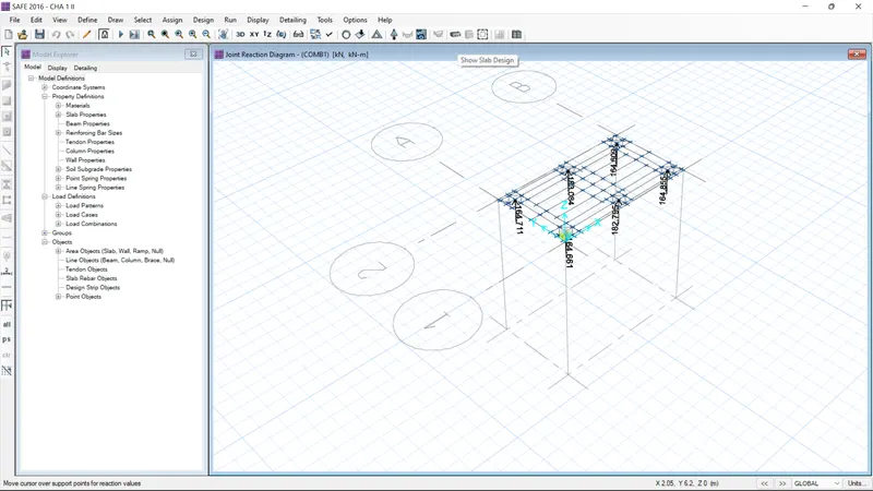
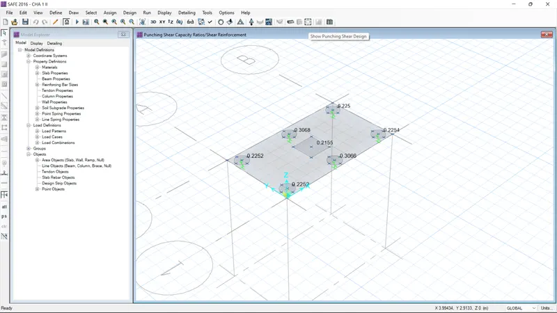
RESULT:
As per the question 2 the model as been designed and analyzed