Fluid Sloshing effect inside a Gear-box Using Ansys-Fluent
Aim
The Major objective of this project was to set up a transient simulation to analyse the Fluid Sloshing effect inside a gearbox using Ansys-Fluent and study the effect of lubrication inside the gearbox with different amount of Engine Oil and n-Heptane.
Introduction
Multiphase flow Engineering is a very important topic of interest when we want to analyse different phases with different state or phases. Phases can be a combination of solid, liquid or gas.
There are three types of interphase in Multiphase engineering:
1. Separated Phase
2. Mixed Phase
3. Dispersed Phase
Earlier black-box approach model did not provide information about flow visualization.

There are many flow regimes that can be seen in multiphase flow engineering.
The details of different flow regimes are represented in the flow regime map for various setup of control parameters but for a specific problem.
Following cases are studied in this project
- 20% Immersion, Fluid - Engine oil.
- 30% Immersion, Fluid- Engine oil.
- 20% Immersion,Fluid-n-heptane (c7h16).
- 30% Immersion,Fluid-n-heptane (c7h16)
###############################################################################################
1.Geometry Creation:
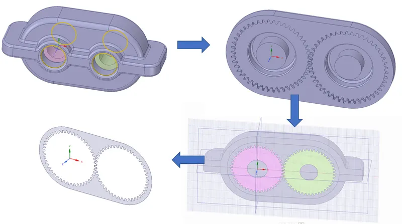
The Gearbox assembly Geometry was designed using a separate cad package using Solidworks. Then the geometry was imported to Ansys design modular for future control volume creation as it defines the fluid flow domain important for Multiphase interaction. First, the fluid flow domain was created using Prepare feature. Then, A 2D plane was created and the 2D volume was extracted from that plane and was imported into a new design file.
2. Boundary Creation and Meshing
After the control volumes are perfectly created the boundary tags were created in order to assign the different boundary conditions ie. velocity, temperature(if needed), or some other physics. For this geometry, 3 different boundary tags or names were created that were used earlier to assign the boundary condition. The 3 names are Left, Right and wall(No slip)
Mesh was generated using trigonal shape elements, in order to make it more refine the body sizing method for chosen for each named selection.
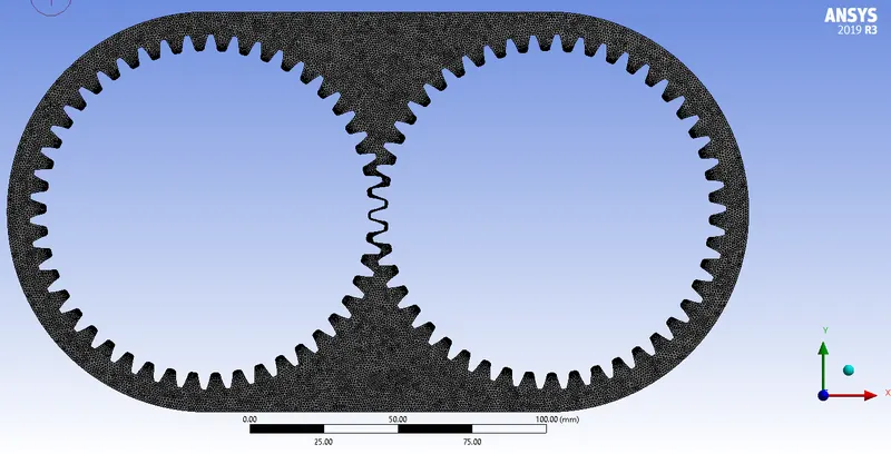
Base Mesh Size:14mm
Face Sizing: Trigonal with 0.8mm element
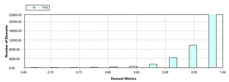
| Number of Nodes | 21459 |
| Number of Elements | 39070 |
3. Case Study Setup
For setting up the case study Ansys Fluent was used in order to simulate the case study.
The various parameter was considered while setup this case study. The case study setup dock was used to set up the problem which appears on the left-hand side of the Fluent studio
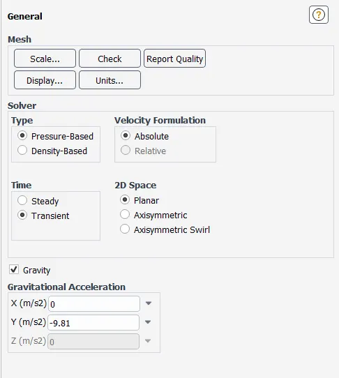
Solver type: Pressure Based Transient State simulation
| S.No. | |||
| 1 | Models |
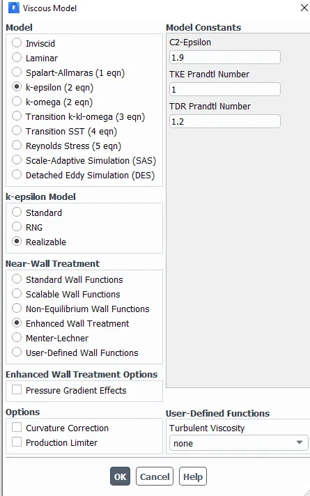
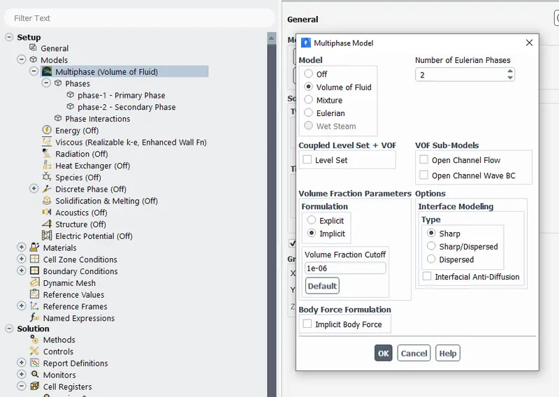
Viscous Model-`K-epsilon -"Standard"` with Enhanced Wall Treatment Multiphase-VOF-2 Phases with implicit scheme |
Viscous was Coupled with a Multiphase model |
| 2 | Material |
Primary phase:`Air (N2:O2::23%:77%)` Secondary Phase Engine oil or N-Heptane |
Air was permanent phases for both the cases |
| 3 | Cell Zone Condition |
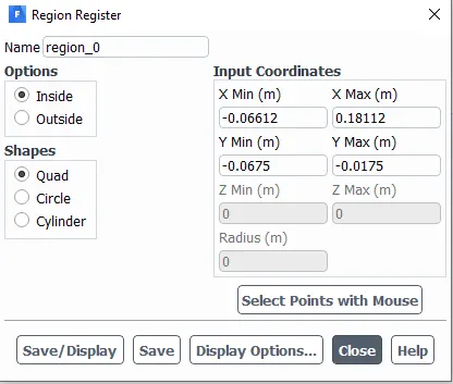
Control Volume Region was set to Air A cell region was registered for Engine oil and N-Heptane |
 |
| 4 | Boundary Conditions | Outer wall No-slip walls | Friction wall near to the wall |
| Left Screw:200rpm(Clockwise) | Using UDF | ||
| Right screew: 200rpm(anticlockwise) | using UDF | ||
4. Solution
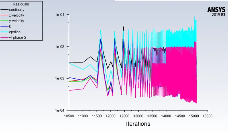
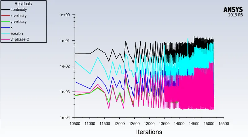
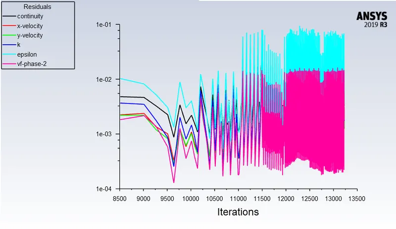
For the Solution Residuals Monitor, the Magnitude was changed to 1e-6 to get more accuracy.
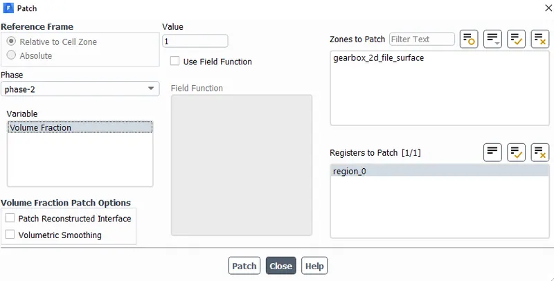
Hybrid Intilizization was used in order to initialize this simulation. The cell register region was patched with volume fraction 1 with the second phase.
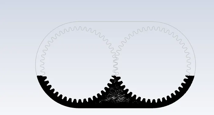
Solution Scheme
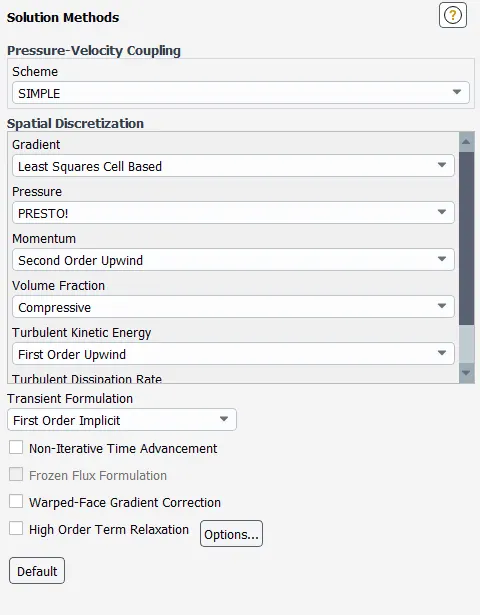
As this was a transient Simulation so the Fixed Simulation was run for 10000 Iterations with step size 0.0001 and the results were generated easily.
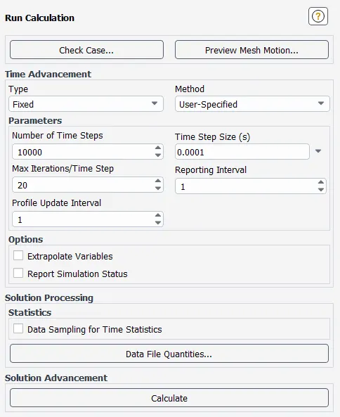
Residua Plot
|
|
2. 20% Immersion,Fluid-n-heptane (c7h16). |
|
3. 30% Immersion, Fluid - Engine oil. |
4. 30% Immersion,Fluid-n-heptane (c7h16). |
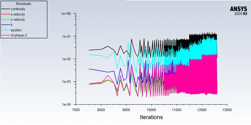
The volume of Fraction Contours:
- 20% Immersion, Fluid - Engine oil.
2. 20% Immersion,Fluid-n-heptane (c7h16).
3. 30% Immersion,Fluid-n-heptane (c7h16).
4. 30% Immersion, Fluid- Engine oil.
Observation:
1. Meshing plays a very important role as more refined is the mesh more VOF can be observed with the shaped boundary between different phases.
2. The use of Engine oil help is pepper and efficient lubrication as it is highly viscous and compared to n-heptane.
3. 30% fluid immersion provides better lubrication for more number of tenths of heart as compared to 20% immersion.
4. N- heptane is less viscous, so it settles down more after as compared to engine oil which is more viscous.
5. Fluid property such as density viscosity plays an important role in lubrication of teeth of gears.
6. It was observed that Engine oil sticks to the gearbox wall surface.
7. More percent volume of lubricant improves the lubrication and more thick layer can be observes on the casing walls of the gear box
1. Dynamic Mesh
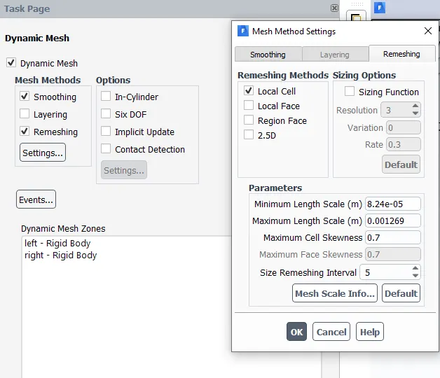
In ANSYS FLUENT the dynamic mesh capability is used to simulate problems with boundary motion, such as check valves and store separations. The building blocks for dynamic mesh capabilities within ANSYS FLUENT are three dynamic mesh schemes, namely, smoothing, layering, and remeshing. A combination of these three schemes is used to tackle the most challenging dynamic mesh problems. However, for simple dynamic mesh problems involving linear boundary motion, the layering scheme is often sufficient.
Examples:
- Any solid immersed in a fluid-like boat.
- IC's engine piston motion.
- Simulation of turbomachines
2. User-Defined function
They are special function which is called in the Ansys fluid library to define the complete physics of the problem and require knowledge of C++ programming to make UDF.
In this case, a Visual basic command prompt was used to launch the Fluent that enables us to load UDF inside fluent.
UDF can be used in many engineering applications such as:
- Assigning the custom Boundary conditions such as custom velocity, motion custom properties etc.
- Materials Property definitions
- Adjust computed values on a once per iteration basis.
- Enhance to achieve multiple values during post-processing.
#include "udf.h"

DEFINE_CG_MOTION(right_motion, dt, vel, omega, time, dtime)
{
	vel[0] = 0.0;
	vel[1] = 0.0;
	vel[2] = 0.0;

	omega[0] = 0.0;
	omega[1] = 0.0;
	omega[2] = 2.0e2; /* [rad/s]*/
}
DEFINE_CG_MOTION(left_motion, dt, vel, omega, time, dtime)
{
	vel[0] = 0.0;
	vel[1] = 0.0;
	vel[2] = 0.0;

	omega[0] = 0.0;
	omega[1] = 0.0;
	omega[2] = -2.0e2; /* [rad/s]*/
}
In our case, a simple UDF was created to assign the motion of gear with 200rpm.
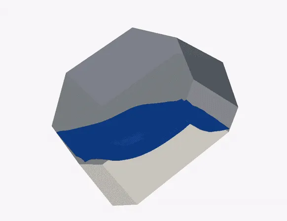
3. Fluid Sloshing Effect
Fluid Sloshing Effect Means irregularly with a splashing sound. "water in the boat sloshed about under our feet".
In simple words, The liquid must have a Top Free surface to constitute a slosh dynamics problem, where the dynamics of the liquid can interact with the container to alter the system dynamics significantly. It is the main cause of instability of the top surface in the system.
Example:
- Propellent slosh in Spacecraft tanks and Rockets
- Sloshing inside Pertolum tank of truck.
Relevant fluid dynamics non-dimensional parameters include the Bond Number, Weber Number and Reynolds Number.
This is not good as it might lead to an accident in many cases due to disbalance it can be avoided but adding baffles inside tanks to reduce the wave ossiclations.
4. Dynamic Mesh Failed error and Negative Cell volume detected error.
These are a very important error which can often be seen when we try to simulate the complex flow problem with dynamic mesh.
Dynamic Mesh Failed occurs when we try to simulate a dynamic mesh problem and it fails. It occurs when the mesh parameters are not defined properly so refining of mesh is important in that case.
The local Cell remeshing method should be enabled in order to allow deforming boundary cell to be re-meshed as they change the geometry.
It's important to define the minimum & maximum length scale along with cell skewness parameters or clicking on "Default" will solve this issue. This error will also occur when these parameters are wrong.
Negative Cell Volume error means the element has a big distortion. big enough to penetrate the opposite face resulting in negative volume. A local volume generates the unphysical behaviour of equations. For this problem, Hex shape mesh showed this specific error but was solved once the trigonal shape elements were used