NACA0017 AIRFOIL SIMULATION.
1. Objective:-
To Model a Flow over the NACA0017 Airfoil for an angle of attacks 0,2,4,6,8,10 respectively and comparing Lift & Drag forces.
2. Basic:-
2.1 Airfoil Terminologies: An airfoil is defined as the cross-section of a body that is placed in an airstream in order to produce a useful aerodynamic force in the most efficient manner possible. The cross-sections of wings, propeller blades, windmill blades, compressor, and turbine blades in a jet engine and hydrofoils are example airfoils. The basic terms related to the airfoil is as shown below.
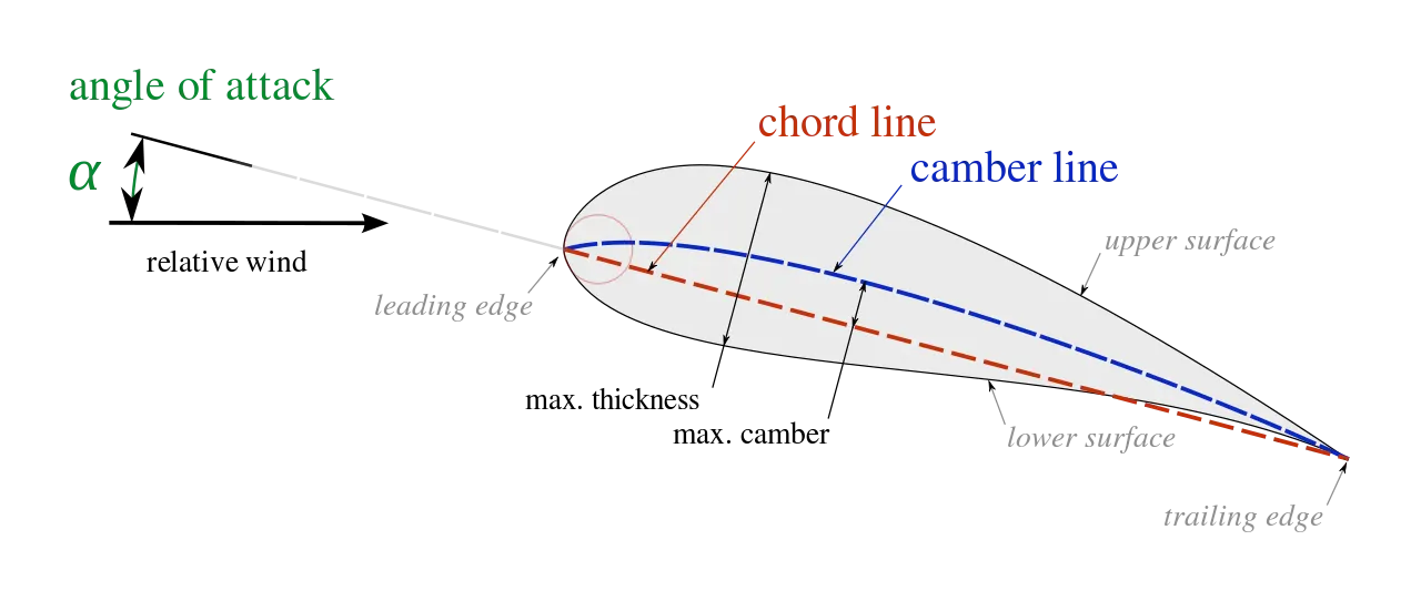
i. The angle of attack: The angle of attack is the angle between the chord line of an airfoil and the oncoming airflow. the symmetrical airfoil will generate zero lift at zero angles of attack. But as the angle of attack increases, the air is deflected through a larger angle, and the vertical component of the airstream velocity increases, resulting in more lift. For small angles, the symmetrical airfoil will generate a lift force roughly proportional to the angle of attack.
ii. Drag Force:
`underset(d) (F) = 1/2*rho*v^2*underset(d) (C)*A`
Where:-
`underset(d) (F) =` Drag force;
ρ = Density of fluid;
v = speed of the object relative to the fluid;
`underset(d) (C) =` Drag Coefficient;
A = Cross-sectional Area.
iii. Lift Force:
Lift depends on the size of the wing, being approximately proportional to the wing area. It is often convenient to quantify the lift of a given airfoil by its lift coefficient, which defines its overall lift in terms of a unit area of the wing.
`L = 1/2*rho*v^2*underset(L) (C)*A`
Where:-
L = Lift force;
ρ = Density of fluid;
v = speed of the object relative to the fluid;
`underset(L) (C) =` Lift Coefficient`
A = Projected Area.
2.2 Other Terminologies:
i. Computational Domain and its Dimensions:
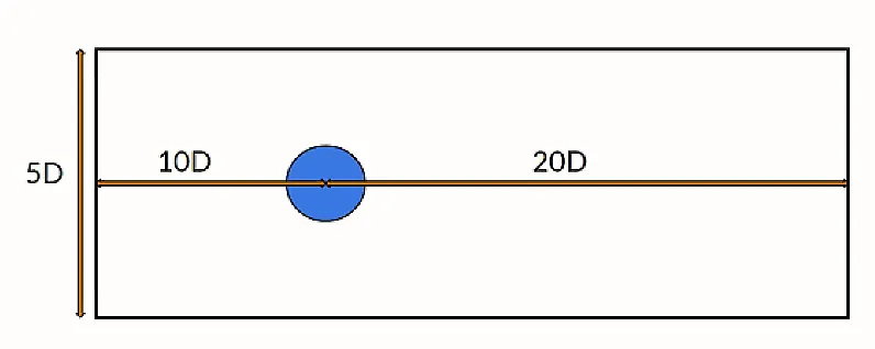
The computational Doman is the simplified form of a physical domain which is sufficient to consider the geometry in the simulation and also to impose the boundary conditions.
this simplified form should retain all physically important features of the problem. considering this as the environment to the system the boundary condition is provided accordingly. here the geometry is cylindrical. also, the basic dimension provided for the computational domain is as shown below.
ii. Total Analysis time(TAT):- The total analysis time defines the physical time period until which the simulation will be run from its initial instant of time.
iii. Output time steps(OTS):- Time step is used in transient solving which denotes the time interval for which the simulation will progress between each iteration/step. in our simulation the time step is 10 for each case.
3. Procedure:-
Step-1: Importing Curve data in the Solidworks by using an insert option.
Step-2: After importing the curve data of NACA0017 airfoil we converted it to the sketch by using convert entities option.
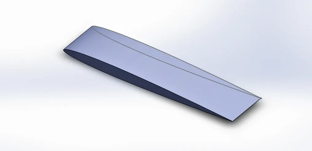
Step-3: After closing the open end of the curve we rotated the model to a different angle (as a requirement in different cases) with the help of the rotation option. After that extruded it to the Desired dimension as shown below.
Step-4: Used flow simulation for the add-ins to analysis. After that, we set up the wizard. In the wizard, we choose the external flow option, and velocity in the x-direction is 600 m/s (For all the cases).
Step-5: Setting mesh to automatic and took local mesh option and the selected surface of the airfoil for better visualization.
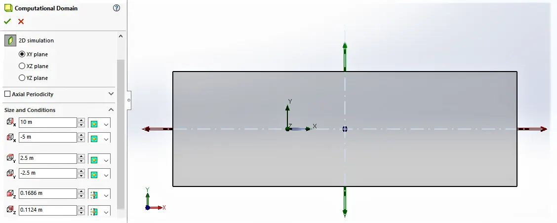
Step-6: Setting Computational domain to the 2D simulation and its Dimensions. 10m in the positive x-direction, -5m in the negative x-direction, 2.5m in the positive y-direction, -2.5m in the negative y-direction.
Step-7: Inserted cut plot and goal for output result and run the calculation.
4. Simulation and Analysis:-
Simulation parameters:
| Unit | : SI |
| Flow type | : External Flow Time-dependent |
| Total Analysis Time | : 5 sec |
| Output Time Step | : 1 sec |
| Working Fluid | : Air |
| Velocity in x-direction | : 600m/s |
| Velocity in Y & Z direction | : 0 |
4.1 Angle of attack 0 Degree:
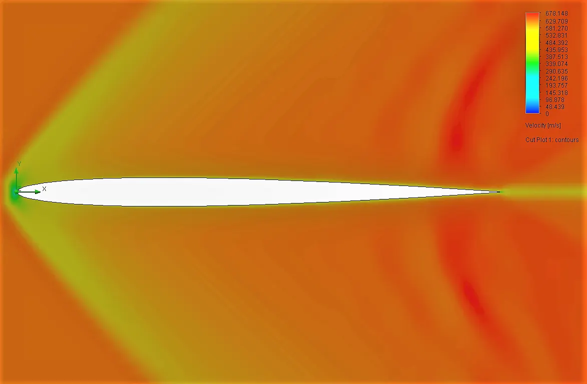
Output:

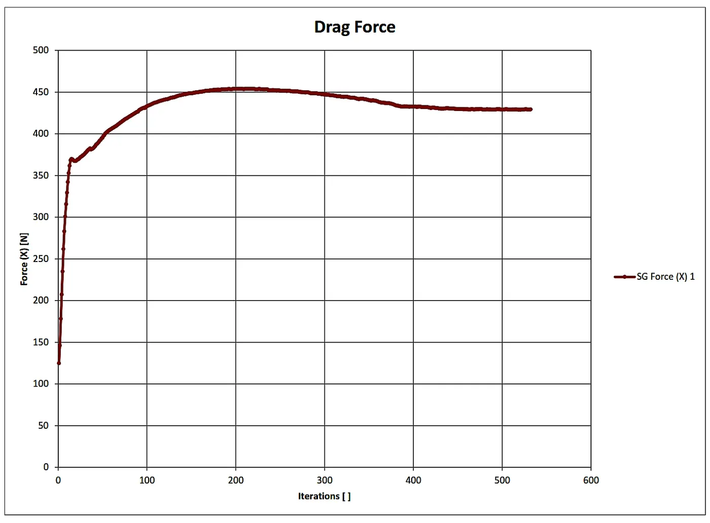
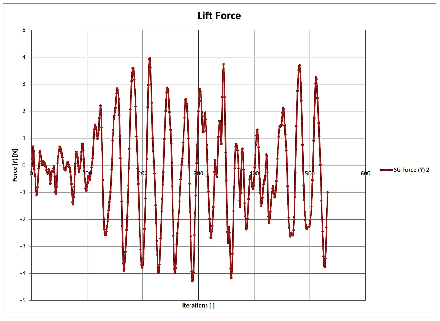
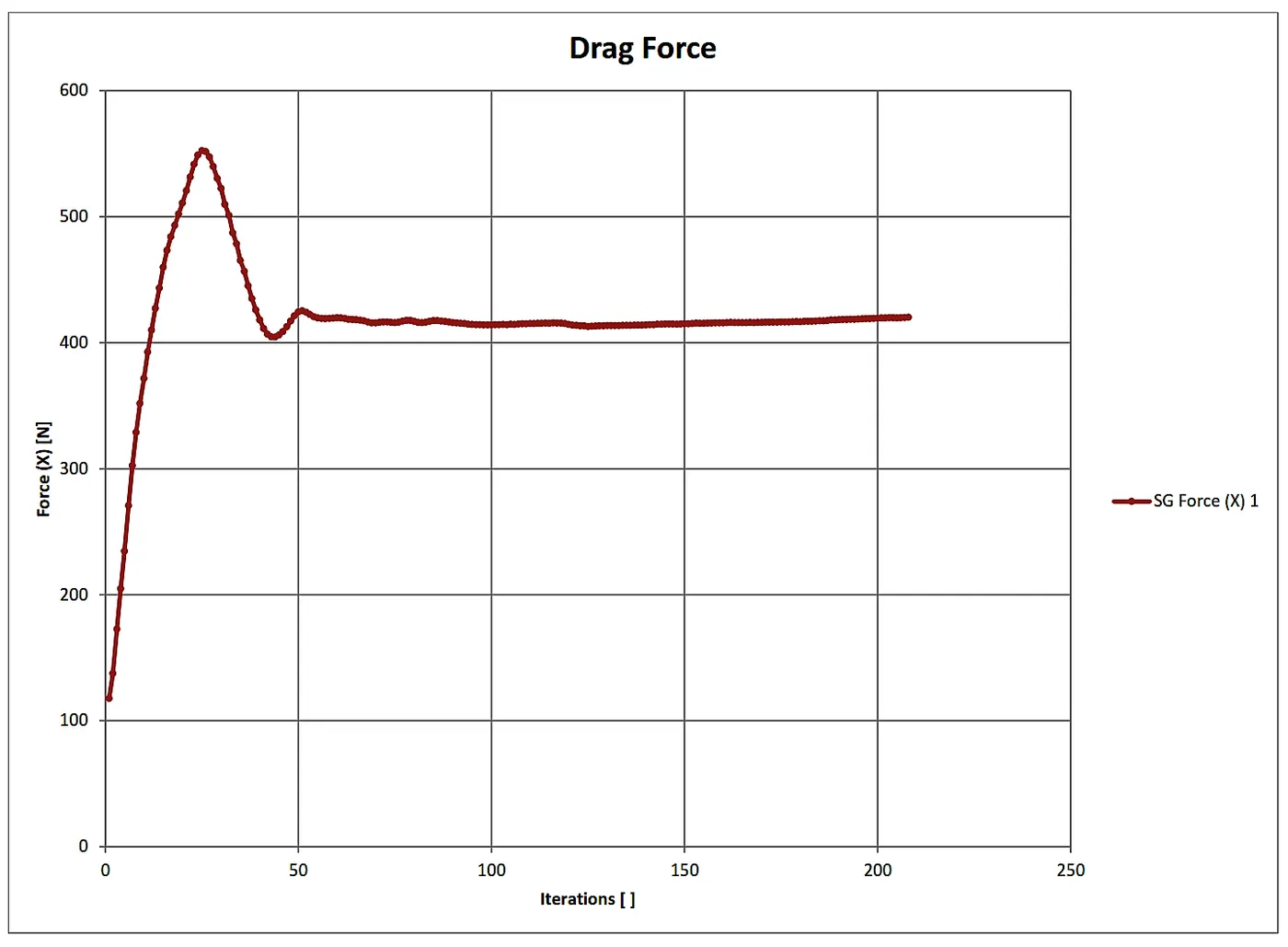
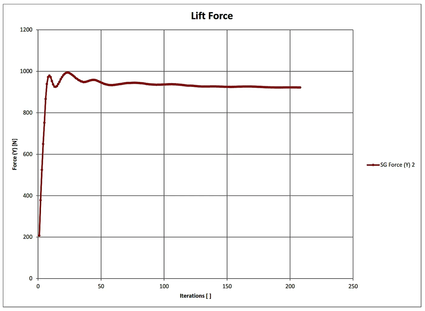
4.2 Angle of attack 2 Degree:
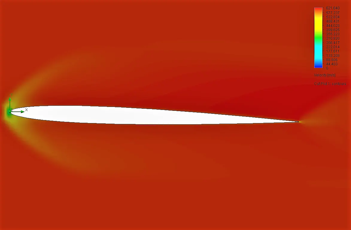
Output:

4.3 Angle of attack 4 Degree:
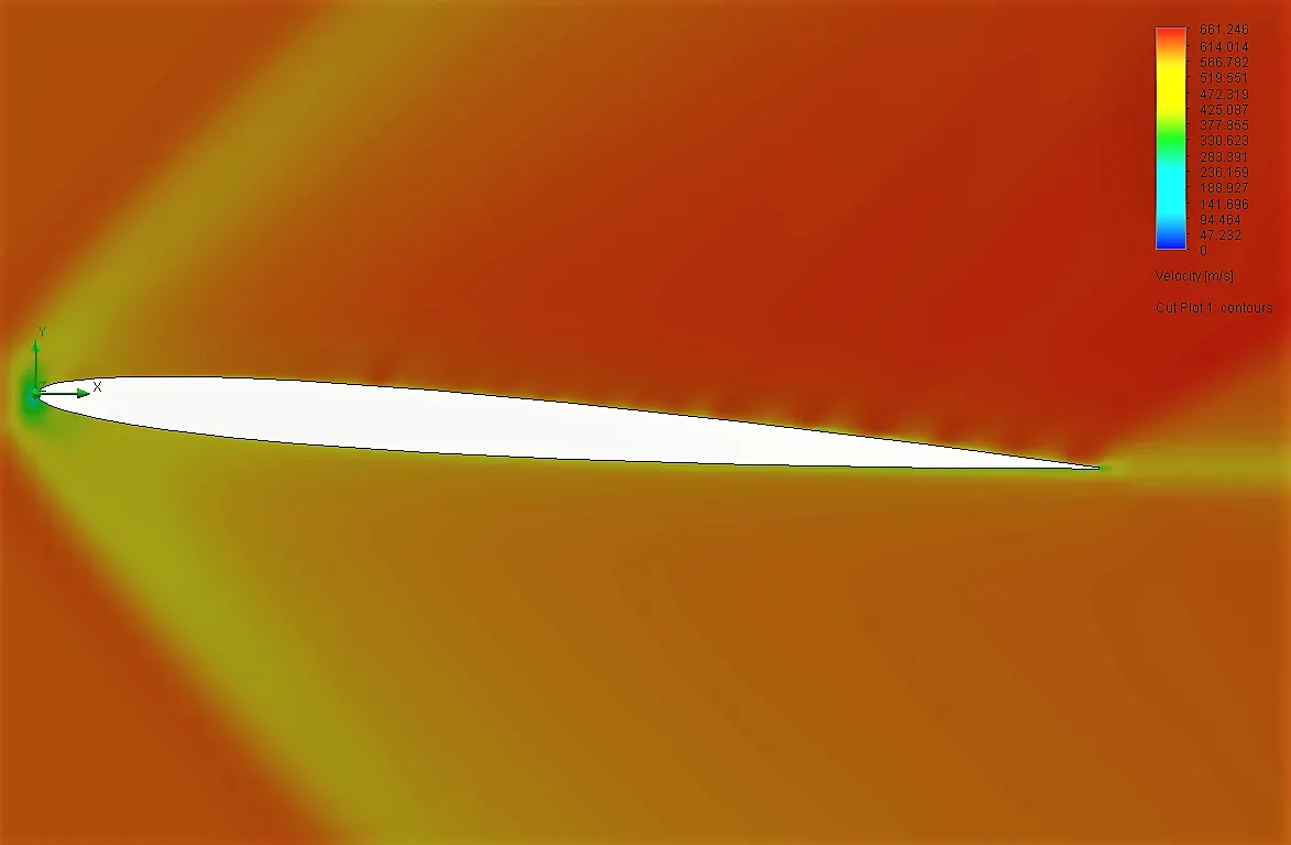
Output:

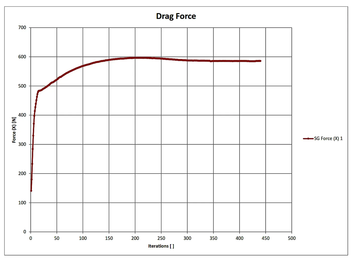
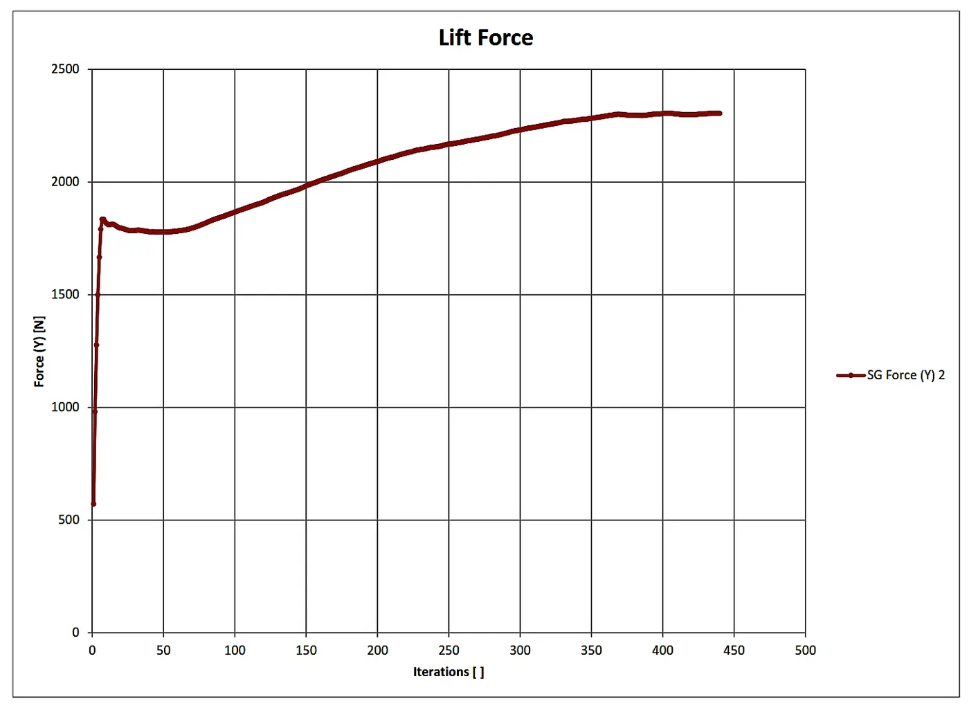
4.4 Angle of attack 6 Degree:
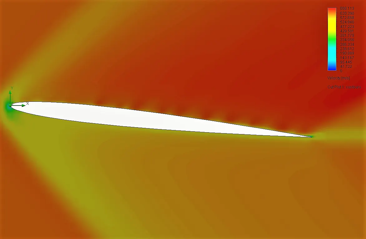
Output:

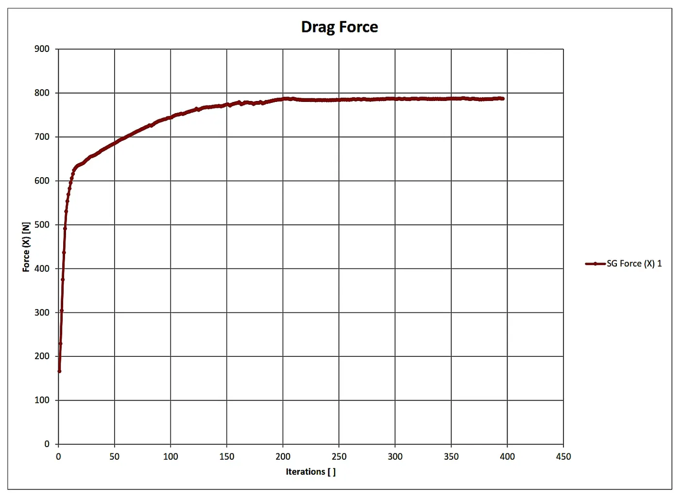
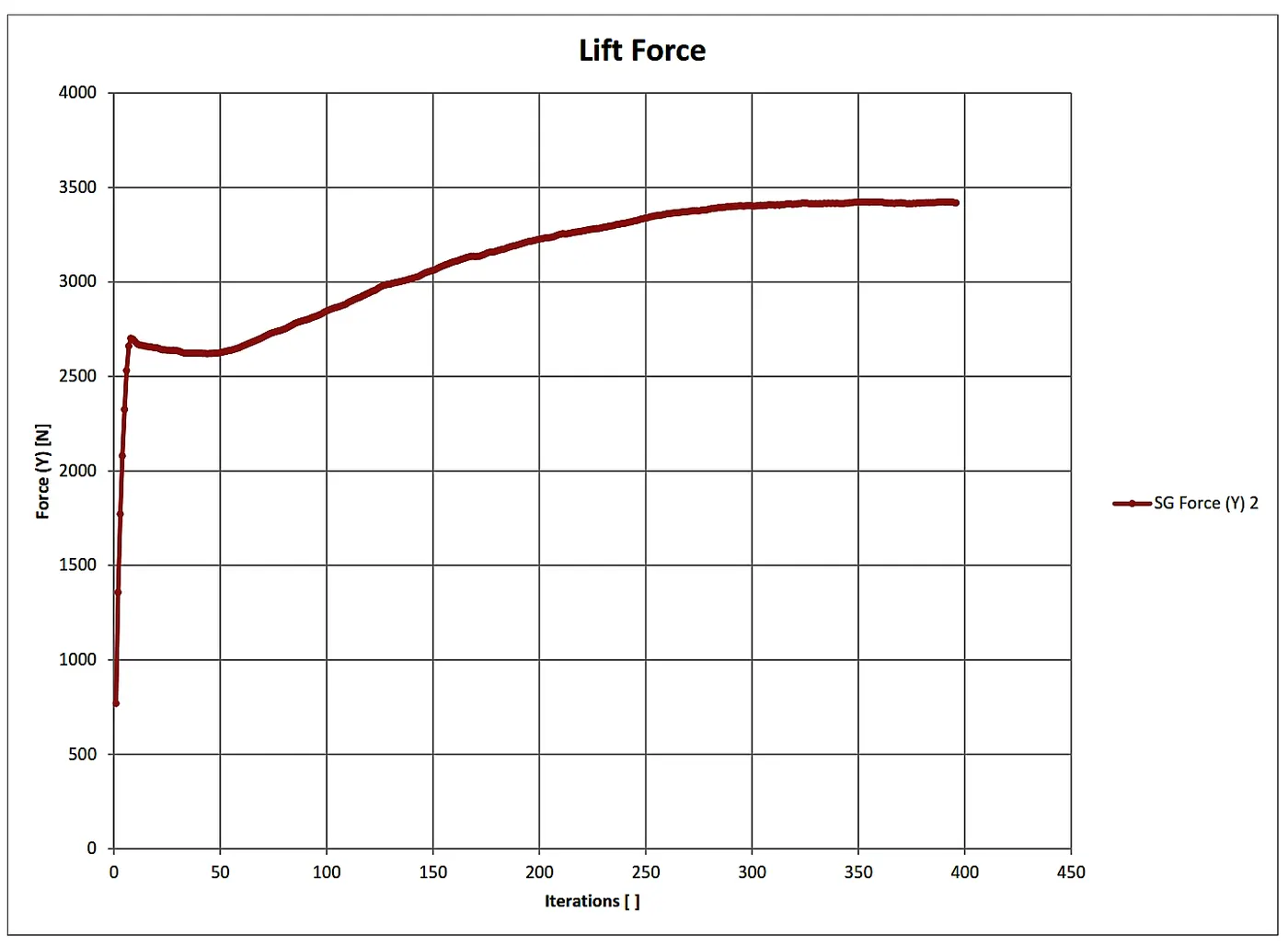
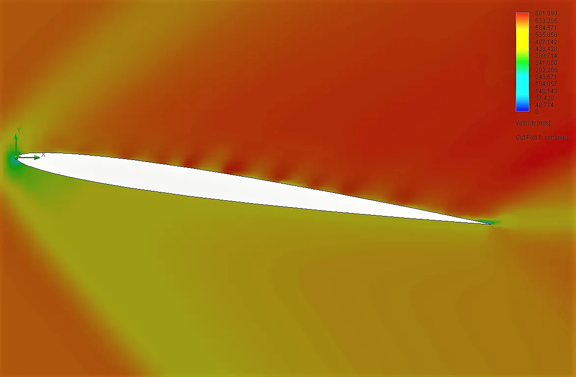
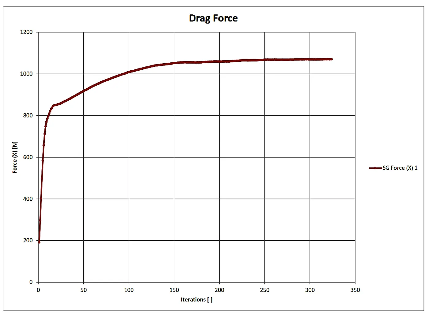
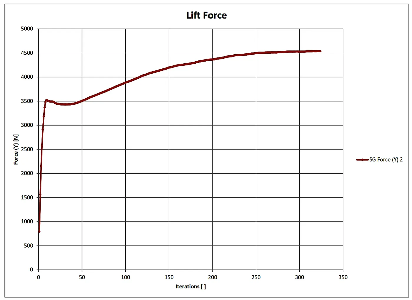
4.5 Angle of attack 8 Degree:
Output:

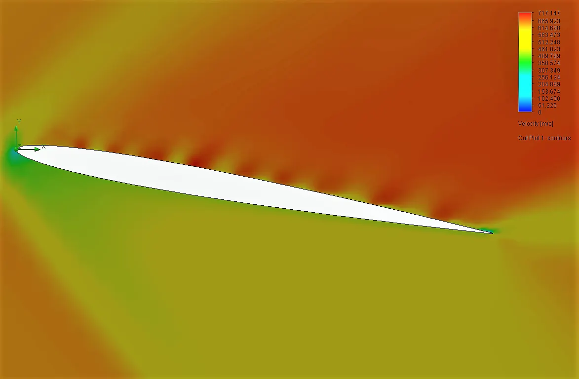
4.6 Angle of attack 10 Degree:
Output:

5. Observation and Conclusion:-
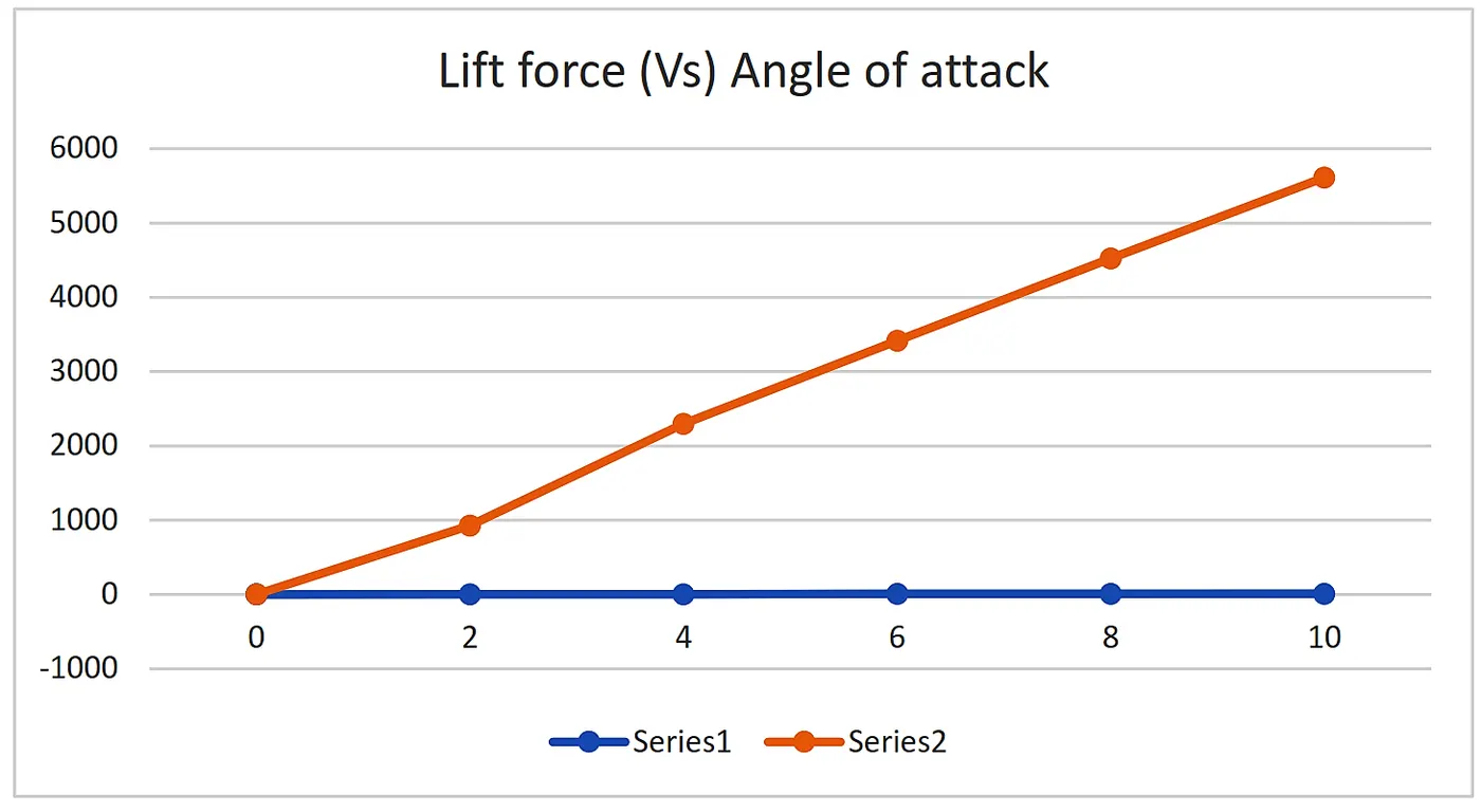
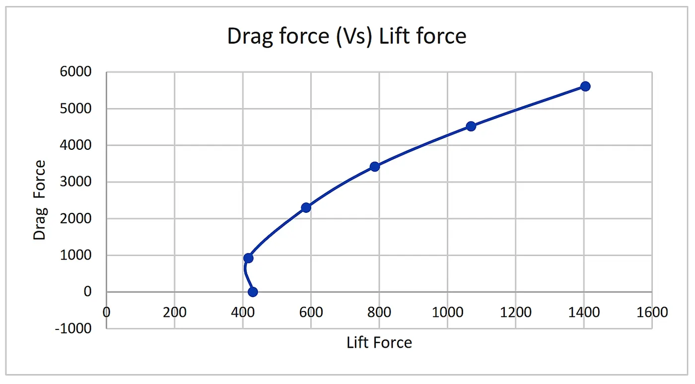
From the Simulation Result, we found the output of the average Drag Force and Average lift force with respect to changes in an Angle of Attack. The following data and animation is can be used to basic visualization of the Behaviour of airfoil in a different angle of attack.
| Angle of Attack | Avg. Drag force | Avg. Lift Force |
| 0 | 429.3711 | -0.18515 |
| 2 | 416.056 | 925.38 |
| 4 | 585.54 | 2299.2 |
| 6 | 786.7 | 3417.819 |
| 8 | 1069.159 | 4520.935 |
| 10 | 1404.1957 | 5612 |
The Graphical Representation of Data is as follows.
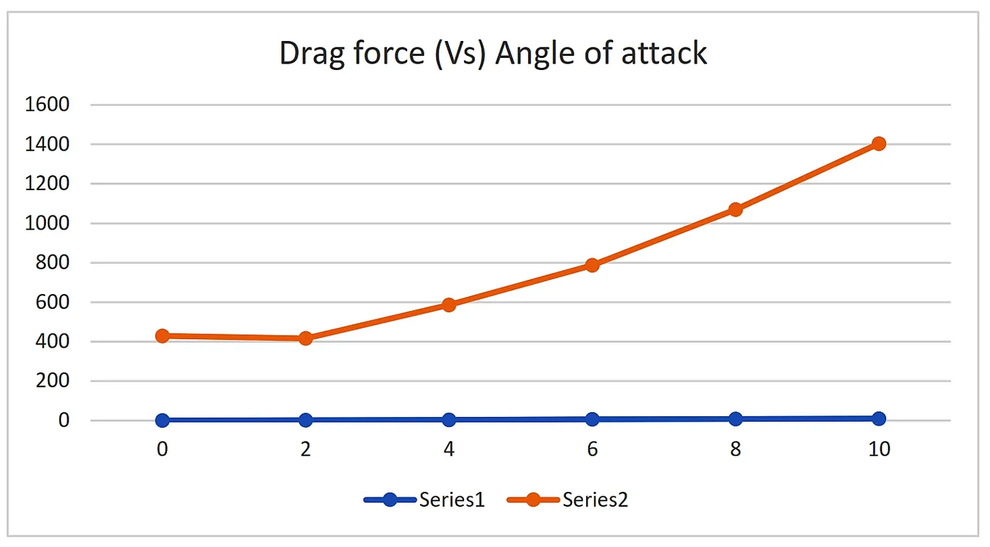
5.1 Average Drag force (Vs) Angle of attack:
X-axis: Angle of Attack
Y-axis: Average Drag force
5.2 Average Lift force (Vs) Angle of attack:
X-axis: Angle of Attack
Y-axis: Average Lift force
5.3 Comparing Drag force (Vs) Lift force:
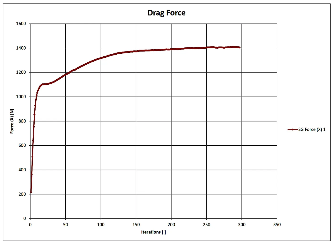
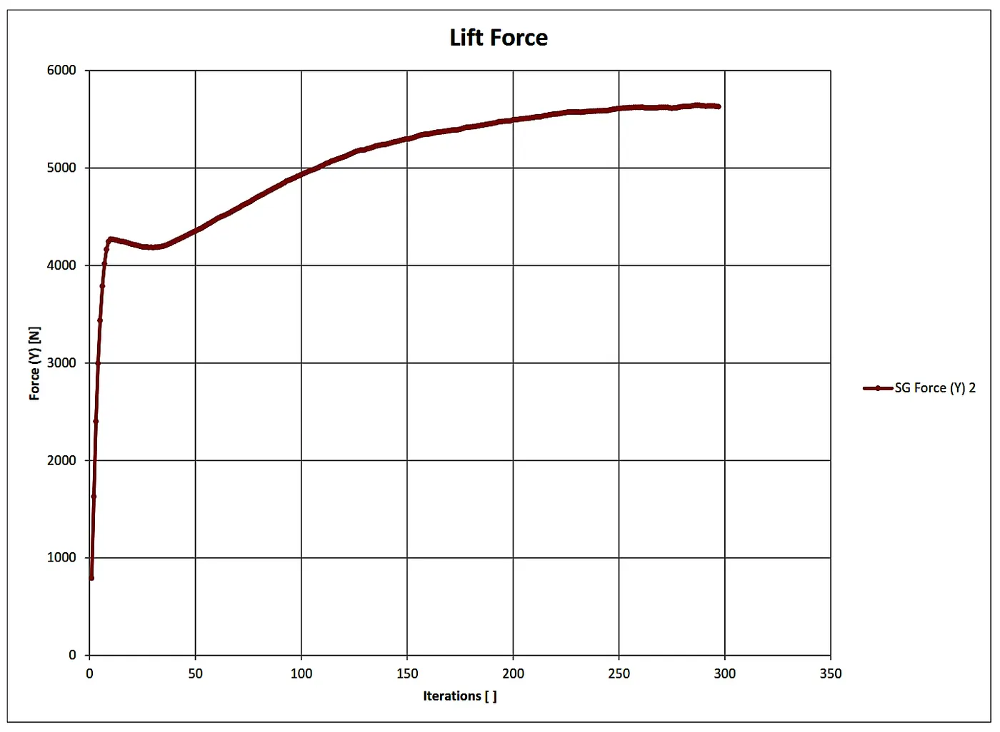
i. At an angle of Attack zero degree, We can see that the airflow is symmetrical and which indicates that the equal fluid flow over the airfoil. The drag force increases initially up to a certain limit and then nearly constant, while the lift force is continuously changing and The average value is near about Zero.
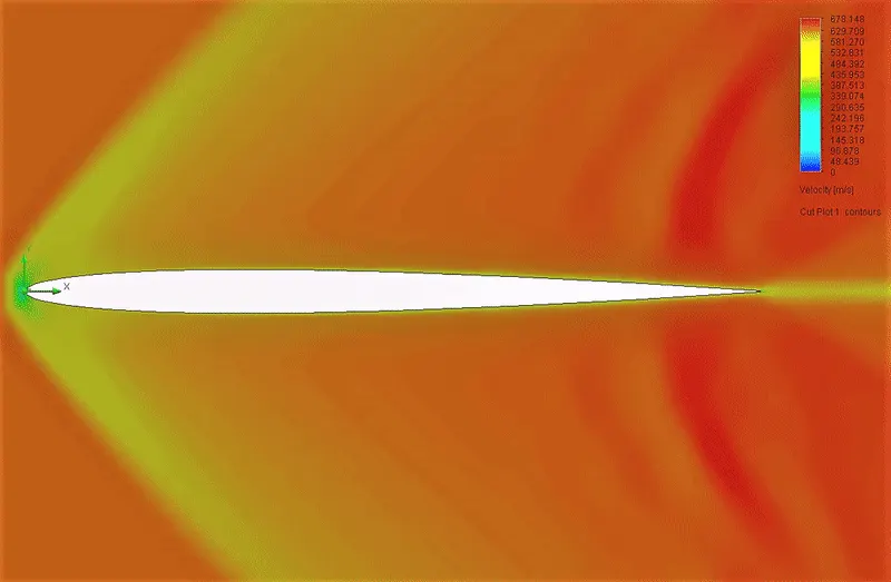
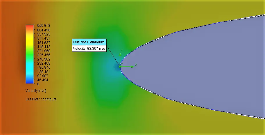
ii. Here, We can see the blue region on the front surface of the Airfoil exposed to the fluid flow which indicates that the point where static pressure is maximum and velocity is minimum Which is also known as Stagnation point.
iii. From the plot of Average Drag force with respect to the angle of attack, we can see that, as the angle of attack increases the Drag Force also increases and makes slight curvature, while from the plot of Average Lift force with respect to the angle of attack, we can see that, as the angle of attack increases the lift Force increases and shows a nearly linear relationship between them. Lift is the component of this force that is perpendicular to the oncoming flow direction and the drag force, which is the component of the force parallel to the flow direction. Lift conventionally acts in an upward direction in order to counter the force of gravity, but it can act in any direction at right angles to the flow.
iv. Also, As the angle of attack increases, the air is deflected through a larger angle, and the vertical component of the airstream velocity increases, resulting in more lift. For small angles, the symmetrical airfoil will generate a lift force roughly proportional to the angle of attack.
Reference:
The Flow of Report:
i. Objective.
ii. Basic.
iii. Procedure.
iv. Simulation and Analysis.
v. Observations and Conclusion.