Flow over an airfoil
...
...
Flow over a airfoil
Aim
Create a Model for Flow Simulation over a NACA0017 airfoil run simulation for different angles of attack 0°,2°,4°,6°,8°,10°.Compare the lift and drag forces.
Theory
An airfoil or aerofoil is a streamlined body that is capable of generating significantly more lift than drag Wings, sails and propeller blades are examples of airfoils. Foils of similar function designed with water as the working fluid are called hydrofoil
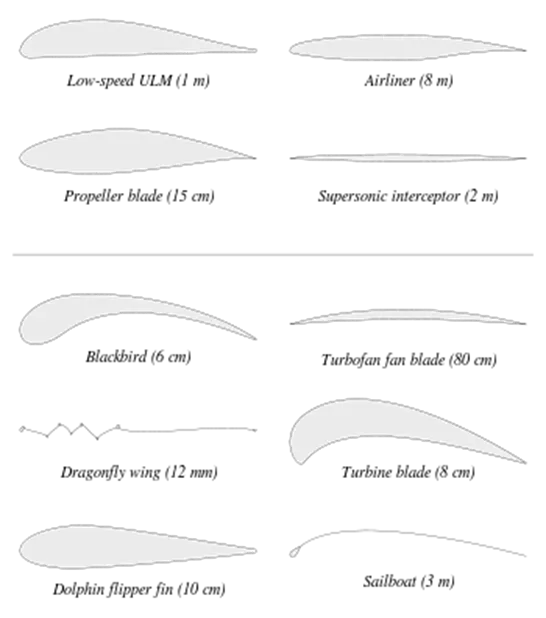
Examples of airfoils in nature and in or on various vehicles. The dolphin flipper at bottom left obeys the same principles in a different fluid medium; it is an example of a hydrofoil Duration: 1 minute and 54 seconds.1:54 Streamlines on an airfoil visualised with a smoke wind tunnel
When oriented at a suitable angle, a solid body moving through a fluid deflects the oncoming fluid (for fixed-wing aircraft, a downward force), resulting in a force on the airfoil in the direction opposite to the deflection This force is known as aerodynamic force and can be resolved into two components: lift (perpendicular to the remote freestream velocity) and drag (parallel to the freestream velocity).
The lift on an airfoil is primarily the result of its angle of attack. Most foil shapes require a positive angle of attack to generate lift, but cambered airfoils can generate lift at zero angle of attack.
Airfoils can be designed for use at different speeds by modifying their geometry: those for subsonic flight generally have a rounded leading edge while those designed for supersonic flight tend to be slimmer with a sharp leading edge. All have a sharp trailing edge.
The air deflected by an airfoil causes it to generate a lower-pressure "shadow" above and behind itself. This pressure difference is accompanied by a velocity difference, via Bernoulli's principle, so the resulting flowfield about the airfoil has a higher average velocity on the upper surface than on the lower surface. In some situations (e.g. inviscid potential flow) the lift force can be related directly to the average top/bottom velocity difference without computing the pressure by using the concept of circulation and the Kutta–Joukowski theorem
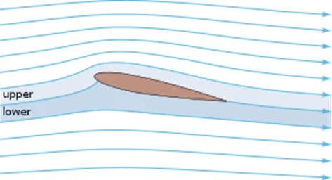
Streamlines around a NACA 0012 airfoil at moderate angle of attack
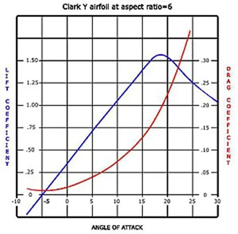
Lift and drag curves for a typical airfoil
The wings and stabilizers of fixed-wing aircraft, as well as helicopter rotor blades, are built with airfoil-shaped cross sections. Airfoils are also found in propellers, fans, compressors and turbines. Sails are also airfoils, and the underwater surfaces of sailboats, such as the centerboard, rudder, and keel, are similar in cross-section and operate on the same principles as airfoils. Swimming and flying creatures and even many plants and sessile organisms employ airfoils/hydrofoils: common examples being bird wings, the bodies of fish, and the shape of sand dollars. An airfoil-shaped wing can create downforce on an automobile or other motor vehicle, improving traction.
When the wind is obstructed by an object such as a flat plate, a building, or the deck of a bridge, the object will experience drag and also an aerodynamic force perpendicular to the wind. This does not mean the object qualifies as an airfoil. Airfoils are highly-efficient lifting shapes, able to generate more lift than similarly sized flat plates of the same area, and able to generate lift with significantly less drag. Airfoils are used in the design of aircraft, propellers, rotor blades, wind turbines and other applications of aeronautical engineering.
A lift and drag curve obtained in wind tunnel testing is shown on the right. The curve represents an airfoil with a positive camber so some lift is produced at zero angle of attack. With increased angle of attack, lift increases in a roughly linear relation, called the slope of the lift curve. At about 18 degrees this airfoil stalls, and lift falls off quickly beyond that. The drop in lift can be explained by the action of the upper-surface boundary layer, which separates and greatly thickens over the upper surface at and past the stall angle. The thickened boundary layer's displacement thickness changes the airfoil's effective shape, in particular it reduces its effective camber, which modifies the overall flow field so as to reduce the circulation and the lift. The thicker boundary layer also causes a large increase in pressure drag, so that the overall drag increases sharply near and past the stall point.
Airfoil design is a major facet of aerodynamics. Various airfoils serve different flight regimes. Asymmetric airfoils can generate lift at zero angle of attack, while a symmetric airfoil may better suit frequent inverted flight as in an aerobatic airplane. In the region of the ailerons and near a wingtip a symmetric airfoil can be used to increase the range of angles of attack to avoid spin–stall. Thus a large range of angles can be used without boundary layer separation. Subsonic airfoils have a round leading edge, which is naturally insensitive to the angle of attack. The cross section is not strictly circular, however: the radius of curvature is increased before the wing achieves maximum thickness to minimize the chance of boundary layer separation. This elongates the wing and moves the point of maximum thickness back from the leading edge.
Supersonic airfoils are much more angular in shape and can have a very sharp leading edge, which is very sensitive to angle of attack. A supercritical airfoil has its maximum thickness close to the leading edge to have a lot of length to slowly shock the supersonic flow back to subsonic speeds. Generally such transonic airfoils and also the supersonic airfoils have a low camber to reduce drag divergence. Modern aircraft wings may have different airfoil sections along the wing span, each one optimized for the conditions in each section of the wing.
Movable high-lift devices, flaps and sometimes slats, are fitted to airfoils on almost every aircraft. A trailing edge flap acts similarly to an aileron; however, it, as opposed to an aileron, can be retracted partially into the wing if not used.
A laminar flow wing has a maximum thickness in the middle camber line. Analyzing the Navier–Stokes equations in the linear regime shows that a negative pressure gradient along the flow has the same effect as reducing the speed. So with the maximum camber in the middle, maintaining a laminar flow over a larger percentage of the wing at a higher cruising speed is possible. However, some surface contamination will disrupt the laminar flow, making it turbulent. For example, with rain on the wing, the flow will be turbulent. Under certain conditions, insect debris on the wing will cause the loss of small regions of laminar flow as well.[7] Before NASA's research in the 1970s and 1980s the aircraft design community understood from application attempts in the WW II era that laminar flow wing designs were not practical using common manufacturing tolerances and surface imperfections. That belief changed after new manufacturing methods were developed with composite materials (e.g. laminar-flow airfoils developed by Professor Franz Wortmann for use with wings made of fibre-reinforced plastic). Machined metal methods were also introduced. NASA's research in the 1980s revealed the practicality and usefulness of laminar flow wing designs and opened the way for laminar-flow applications on modern practical aircraft surfaces, from subsonic general aviation aircraft to transonic large transport aircraft, to supersonic designs.
Schemes have been devised to define airfoils – an example is the NACA system. Various airfoil generation systems are also used. An example of a general purpose airfoil that finds wide application, and pre–dates the NACA system, is the Clark-Y. Today, airfoils can be designed for specific functions by the use of computer programs.
Airfoil terminology
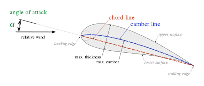
Airfoil nomenclature
The various terms related to airfoils are defined below:
- The suction surface (a.k.a. upper surface) is generally associated with higher velocity and lower static pressure.
- The pressure surface (a.k.a. lower surface) has a comparatively higher static pressure than the suction surface. The pressure gradient between these two surfaces contributes to the lift force generated for a given airfoil.
The geometry of the airfoil is described with a variety of terms
- The leading edge is the point at the front of the airfoil that has maximum curvature (minimum radius).
- The trailing edge is defined similarly as the point of maximum curvature at the rear of the airfoil.
- The chord line is the straight line connecting leading and trailing edges. The chord length, or simply chord �C is the length of the chord line. That is the reference dimension of the airfoil section.
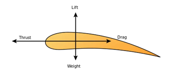
1) Lift Force: Lift force is the force component perpendicular to the direction of relative motion.
FL= (CL.ρ.A.v2)/2
where CL=Lift coefficient
ρ= density of fluid.
A= Area of body
v= fluid velocity
2) Drag force:Drag force is the force component parallel to the direction of relative motion.
FD= (CD.ρ.A.v2)/2
where CD= Drag Coefficient.
3) Thrust force:Thrust force is force created by propellers and jet engines .
4) Weight force: This a body force and not an aerodynamic force.
FLOW SIMULATION :
Simulation is conducted as follows :
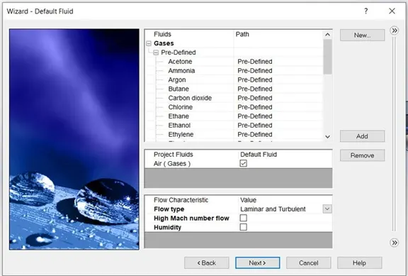
Fluid : Air
Type : External , Time dependent
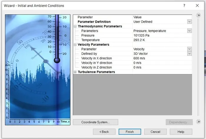
Velocity along X direction : 600m/s
Time duration : 5 s
Interval : 1 s
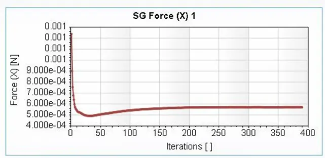
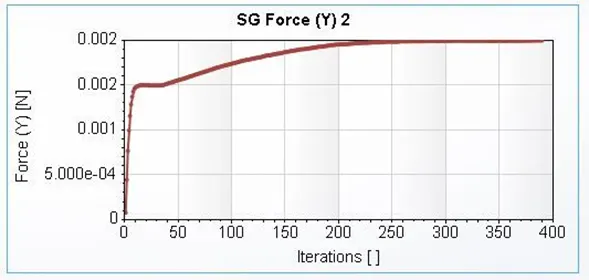
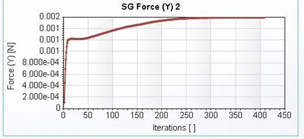
Angle of attack 10 deg :
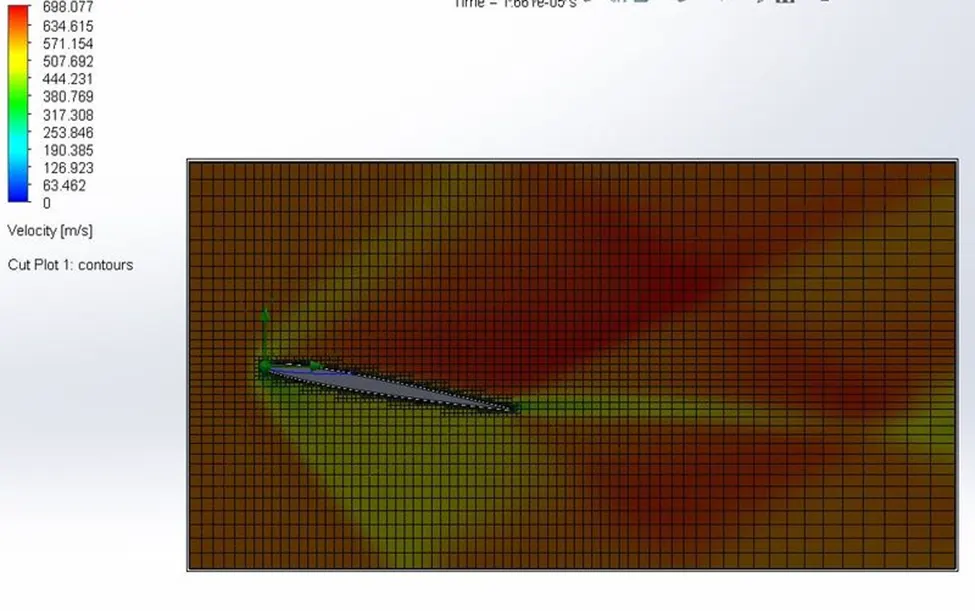
Velocity cut plot
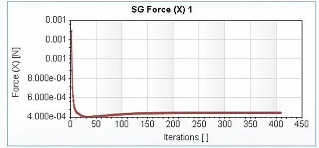
Angle of attack 8 deg :
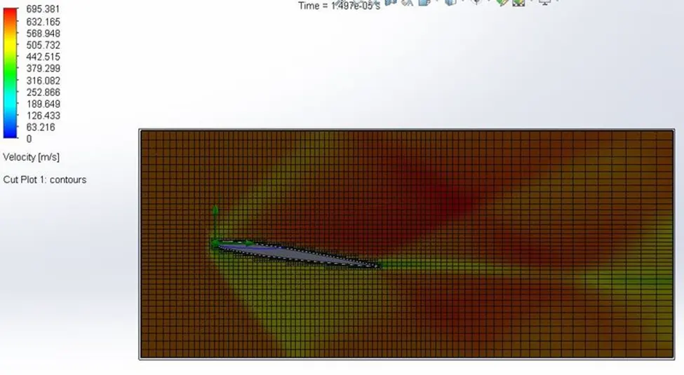
Velocity cut plot
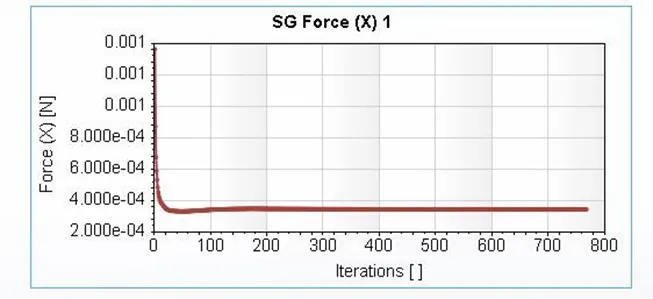
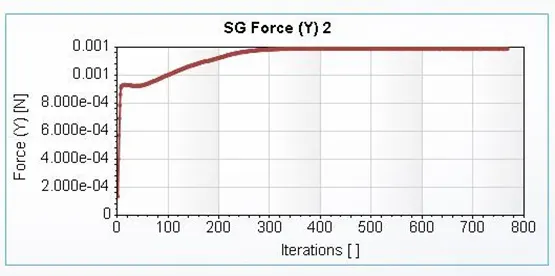
Angle of attack 6 deg :
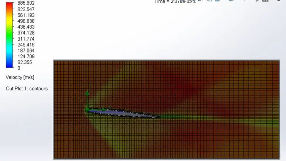
Velocity cut plot
Angle of attack 4 deg :
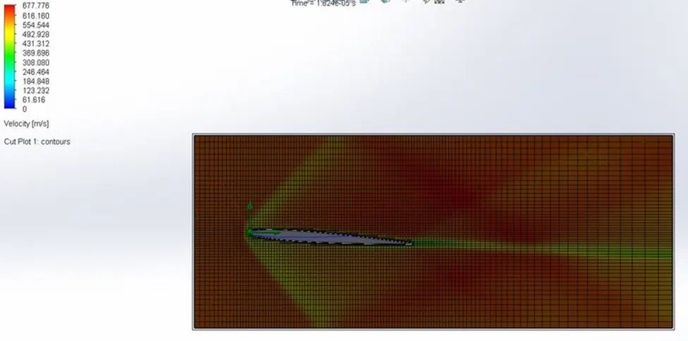
Velocity cut plot
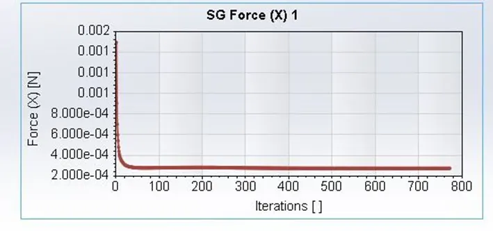
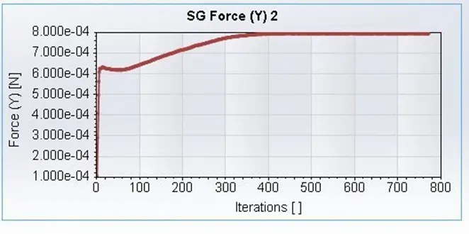
Angle of attack 2 deg :
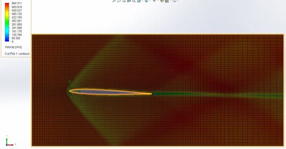
Velocity cut plot
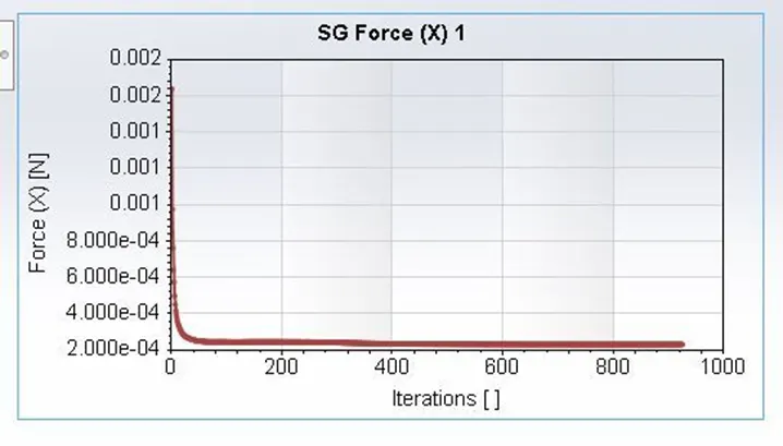

Angle of attack 0 deg :
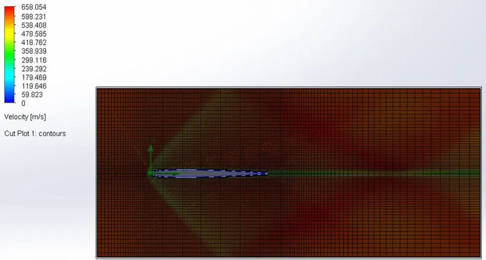
Drag and Lift force
|
Angle of attack |
Drag Force (Fx) |
Lift Force (Fy) |
|
0 |
2.17x10^-4 |
2.67x10^-4 |
|
2 |
2.31x10^-4 |
3.92x10^-4 |
|
4 |
2.75x10^-4 |
7.95x10^-4 |
|
6 |
3.44x10^-4 |
0.001 |
|
8 |
4.54x10^-4 |
0.002 |
|
10 |
5.7x10^-4 |
0.002 |
RESULTS AND OBSERVATION or Conclusions
It is found that the increase in angle of attack increases the drag force in a larger scale compare to increase in the Lift force The increase in angle of attack decreases the increments required to achieve a stagnant value.