Flow over an airfoil
OBJECTIVE:
Model the flow over a NACA0017 airfoil. For the angle of attacks 0,2,4,6,8,10 compare the lift and drag forces
** was not able to upload the airfoil profile of naca0017 so I have made a study on Dayton- wright 6 airfoil
The NACA Airfoils:
The NACA airfoils were designed during the period from 1929 through 1947 under the direction of Eastman Jacobs at the NACA’s Langley Field Laboratory. Most of the airfoils were based on simple geometrical descriptions of the section shape, although the 6 and 6A series was developed using theoretical analysis and don’t have simple shape definitions. Although a new generation of airfoils has emerged as a result of improved understanding of airfoil performance and the ability to design new airfoils using computer methods, the NACA airfoils are still useful in many aerodynamic design applications. A number of references have been included to allow the reader to study both the older NACA literature and the new airfoil design ideas. Taken together, this literature provides a means of obtaining a rather complete understanding of the ways in which airfoils can be shaped to obtain desired performance characteristics.
NACA 4 DIGITS AIRFOIL SPECIFICATION:
This NACA airfoil series is controlled by 4 digits e.g. NACA 2412, which designate the camber, position of the maximum camber and thickness. If an airfoil number is
e.g.
NACA 2412
then:
- M is the maximum camber divided by 100. In the example M=2 so the camber is 0.02 or 2% of the chord
- P is the position of the maximum camber divided by 10. In the example P=4 so the maximum camber is at 0.4 or 40% of the chord.
- XX is the thickness divided by 100. In the example XX=12 so the thickness is 0.12 or 12% of the chord.
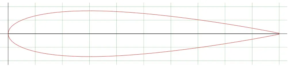
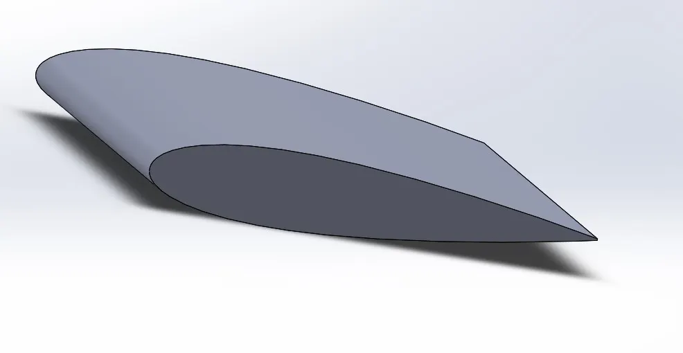
SOLIDWORKS MODEL:
FLOW SIMULATION:
PARAMETERS:
1. External flow simulation
2. Time dependence
3. Velocity in x-direction = 600m/s
GOAL:
1. GLOBAL GOALS:
- FORCE(X)
- FORCE(Y)
- FRICTION FORCE(X)
- FRICTION FORCE(Y)
2. SURFACE GOALS:
- FORCE(X)
- FORCE(Y)
RESULTS AND OUTPUT:
1. ANGLE OF ATTACK: 0 deg
PRESSURE AND VELOCITY CONTOUR:
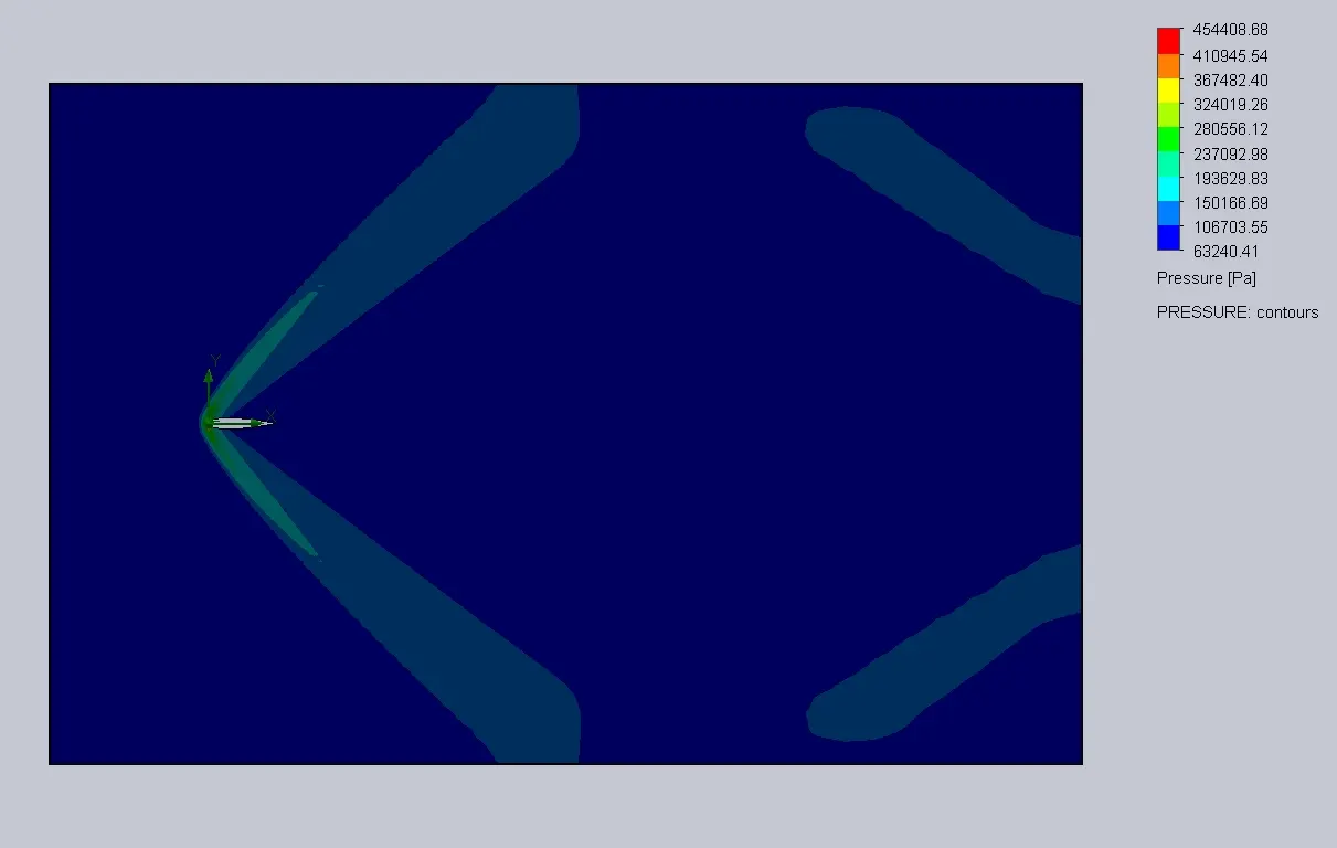
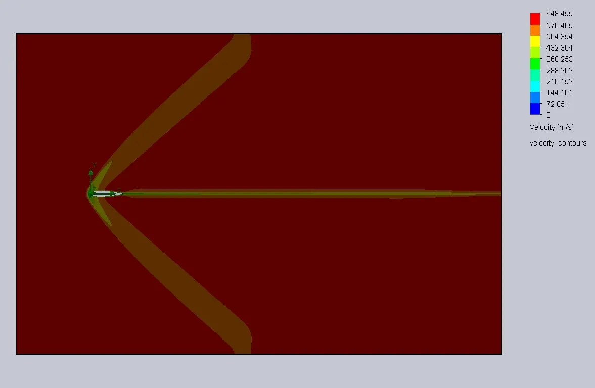
LIFT AND DRAG RESULT:

2. ANGLE OF ATTACK: 2 deg
PRESSURE AND VELOCITY CONTOUR:
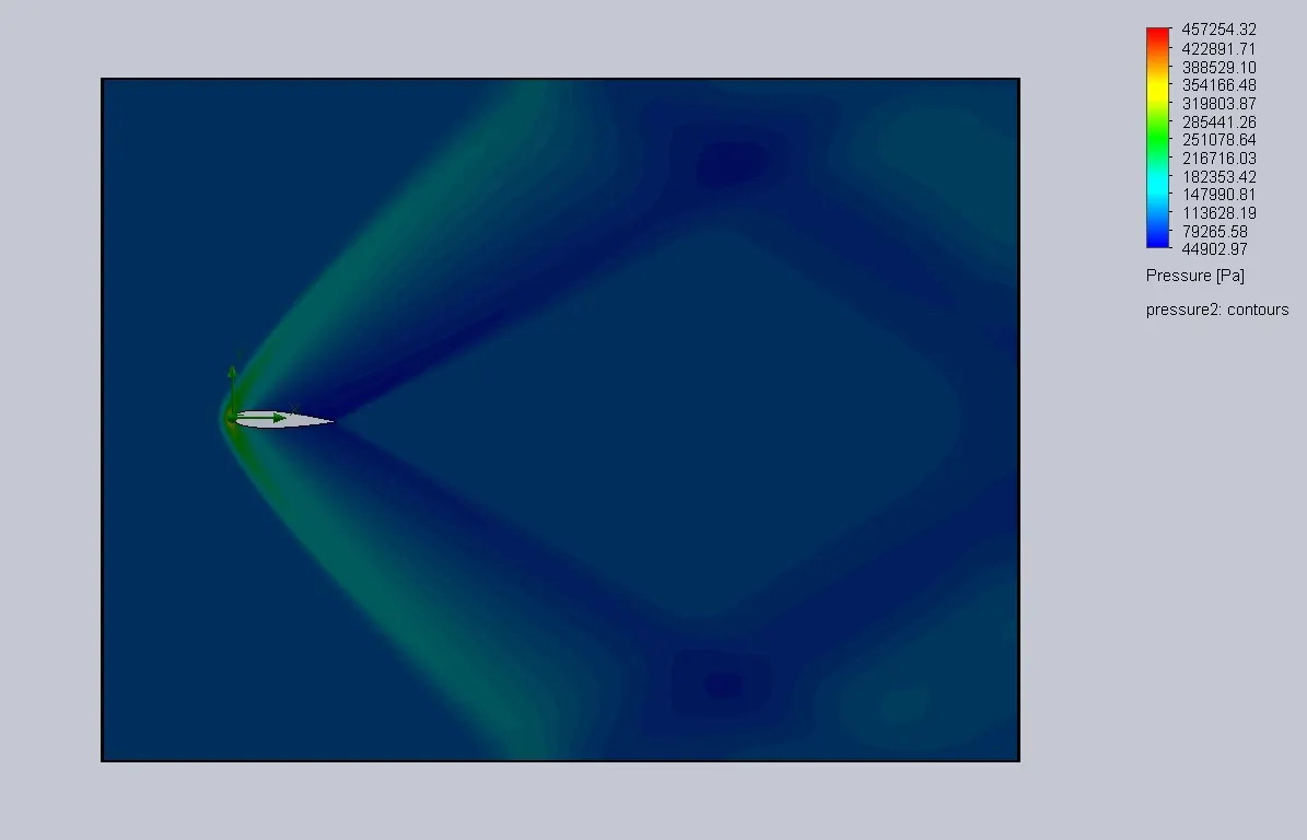
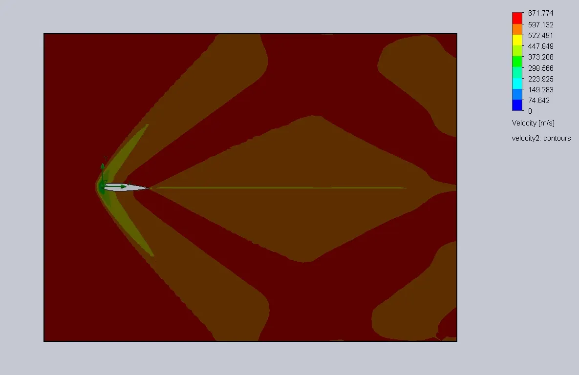
LIFT AND DRAG RESULT:

3. ANGLE OF ATTACK: 4 deg
PRESSURE AND VELOCITY CONTOUR:
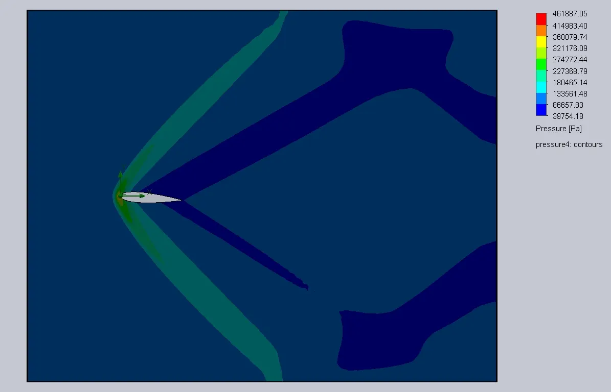
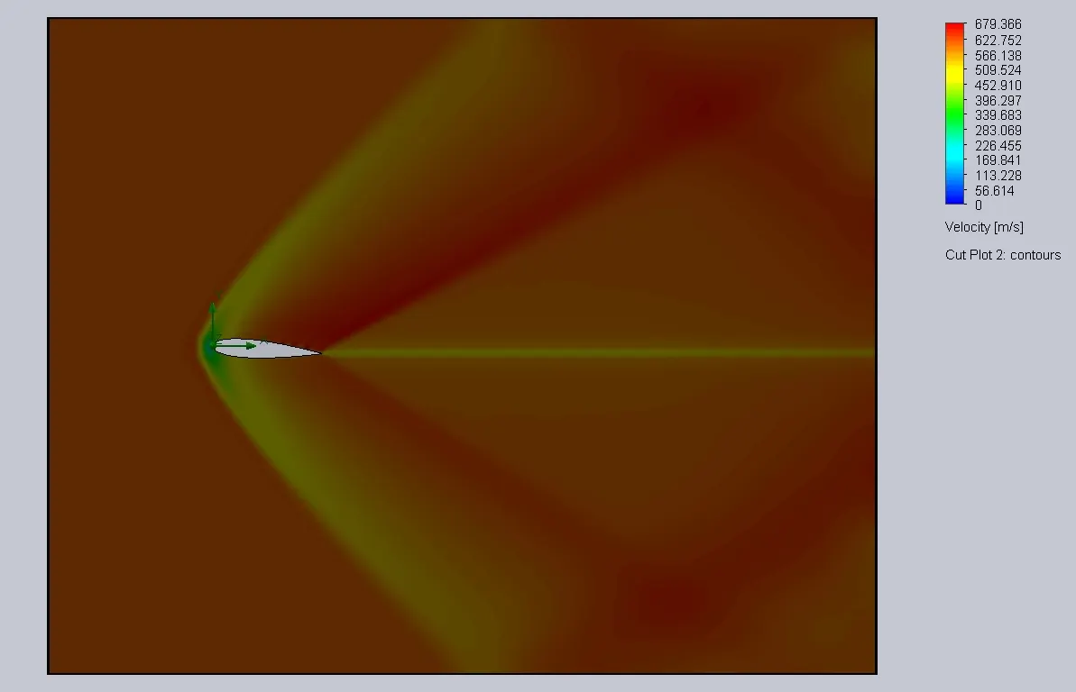
LIFT AND DRAG RESULT:

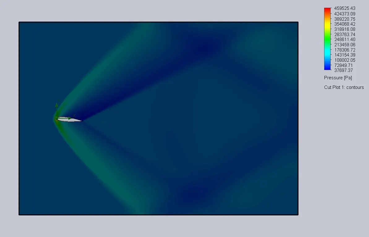
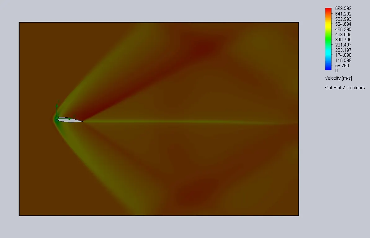
4. ANGLE OF ATTACK: 6 deg
PRESSURE AND VELOCITY CONTOUR:
LIFT AND DRAG RESULT:

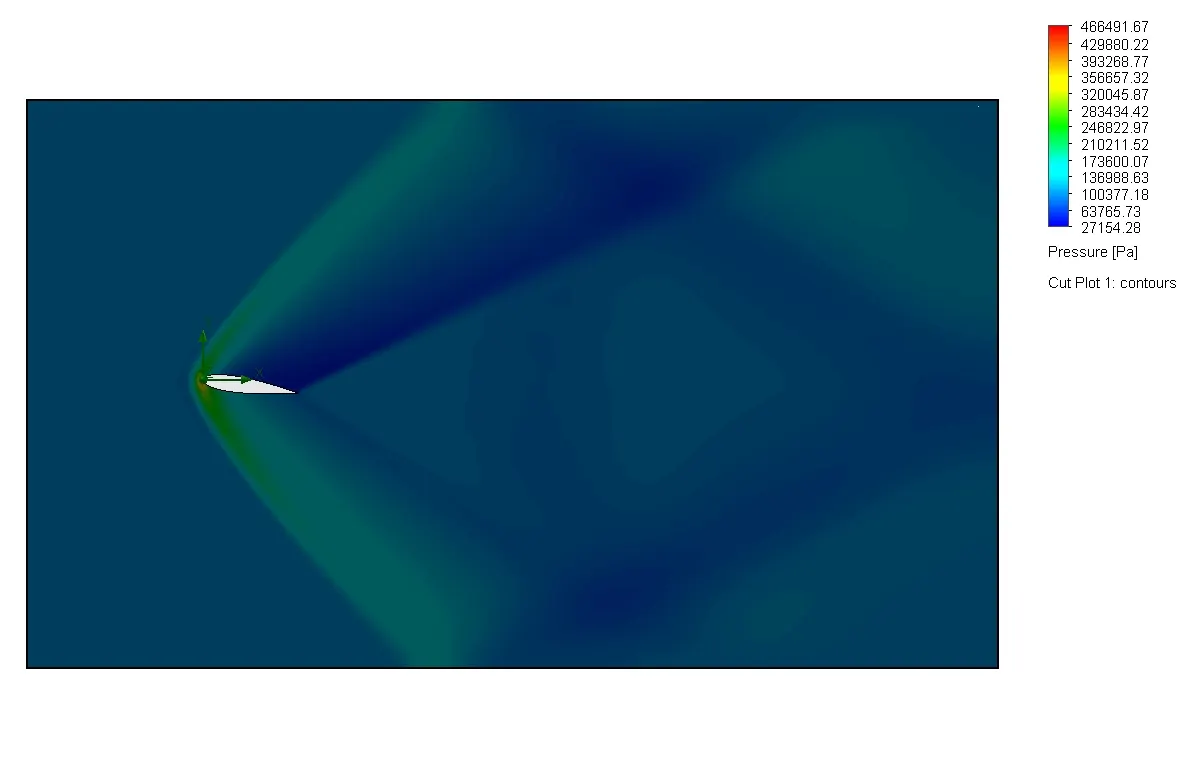
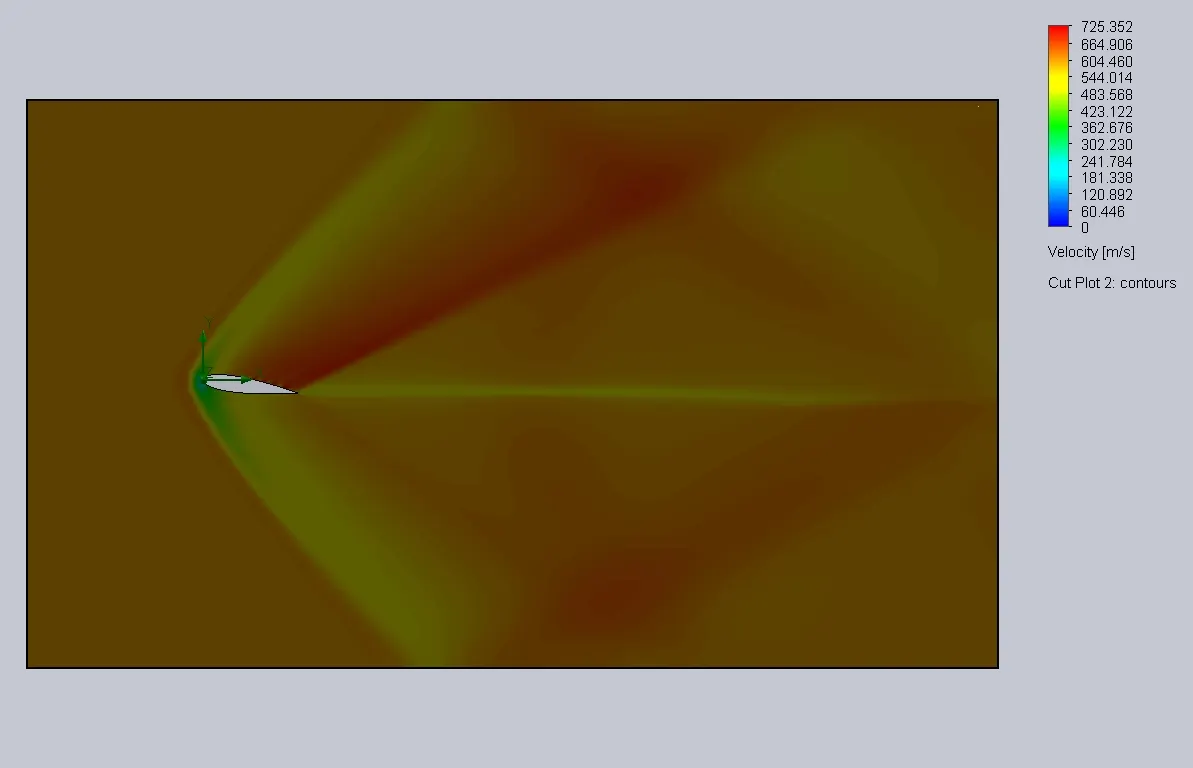
5. ANGLE OF ATTACK: 8 deg
PRESSURE AND VELOCITY CONTOUR:
LIFT AND DRAG RESULT:

6. ANGLE OF ATTACK: 10 deg
PRESSURE AND VELOCITY CONTOUR:
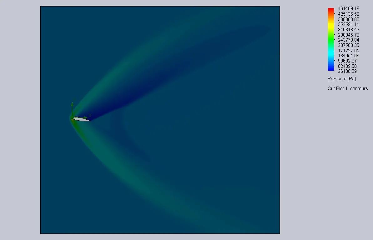
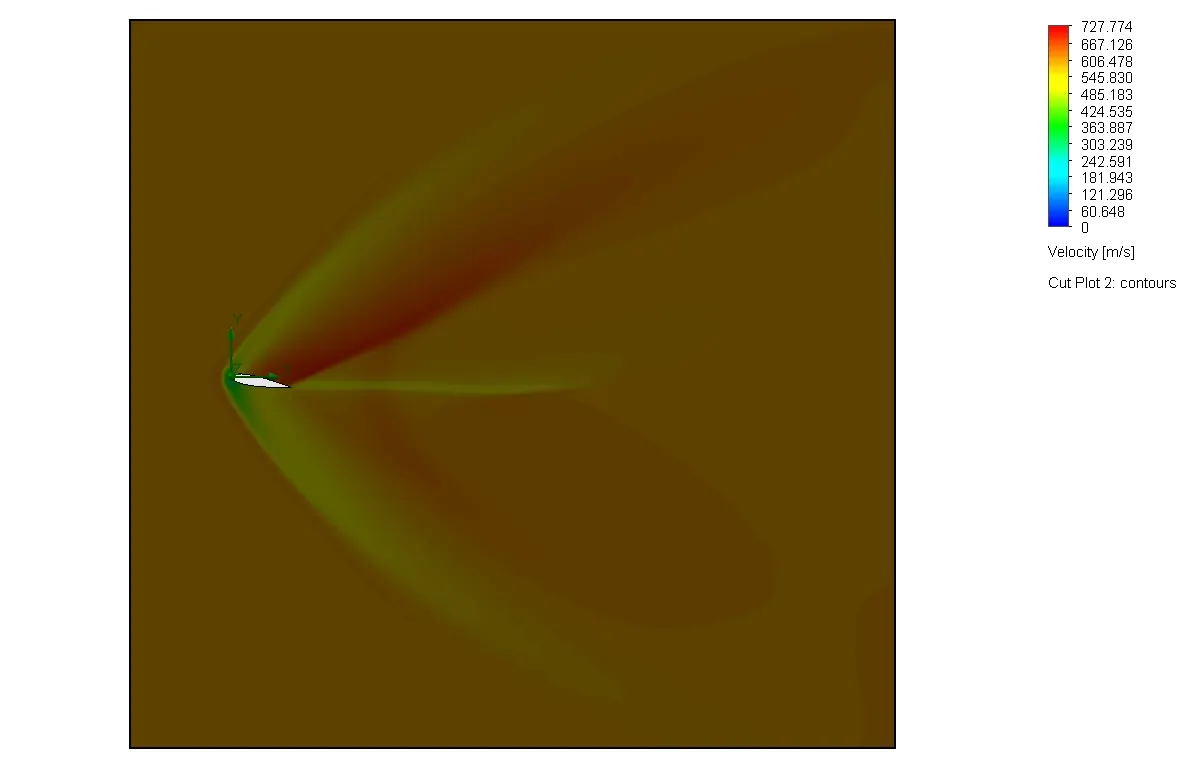
LIFT AND DRAG RESULT:

RESULTS AND OBDSRVATION :
Drag forces and Lift forces are compared at 0,2,4,6,8,10 angle of attack