TO TRANSIENT FLOW OVER A AIRFOIL WITH DIFFERENT ANGLE OF ATTACK BY USING SOLIDWORKS
AIM :
To create a NACA 0017 airfoil in solidworks and analysing that model with different angle of attack.
FLOW OF CONTENT/METHODOLOGY :
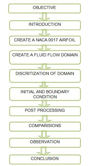
OBJECTIVE :
1) Import the NACA 0017 airfoil data proper mannerly into the solidworks.
2) Analyzing the airfoil with different angle of attack from 0 to 10 degree with five uniform intervals.
3) Extracting the useful data from numerical modal such as drag force and lift force for all cases.
4) Comparing the lift and drag force for all cases.
INTRODUCTION :
Airfoil :
An airfoil is the cross sectional shape of a wing, an airfoil shaped body moving through a fluid produces an aerodynamic force. The component of this force perpendicular to the direction of motion is called lift. The component parallel to the direction of motion is called drag.
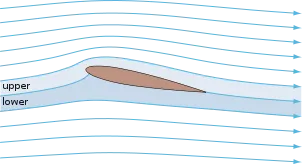
The lift on an airfoil is primarily the result of its angle of attack. When oriented at an stall angle, the airfoil deflects the oncoming air for fixed wing aircraft a downward force, resulting in a force on the airfoil in the direction opposite to the deflection. This force is known as aerodynamic force and can be resolved into two components like lift and drag. Most foils shapes require a positive angle of attack to generate to lift, but camber airfoil can generate lift at zero angle of attack. The turning of the air in the vicinity of the airfoil creates curved streamlines, resulting in lower pressure on one side and higher pressure on other side. this pressure difference is accompanied by a velocity difference, via Bernoulli's principle, so the resulting flowfield about airfoil has higher average velocity on the upper surface than on the lower surface.
Airfoil terminology :
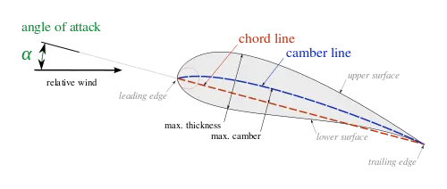
The various terms related to airfoils are defined below
- The upper surface or suction surface is generally associated with higher velocity and lower static pressure.
- The pressure surface or lower surface has a comparatively higher static pressure than the suction surface. The pressure gradient between these two surfaces contributes to the lift force generated for a given airfoil.
The geometry of the airfoil is described with a variety of terms
- The leading edge is a point at the front of the airfoil that has maximum curvature with minimum radius.
- The trailing is defined similarly as the point of maximum curvature at the rear of the airfoil.
- The chord line is the straight line is connected leading and trailing edge. The chord length or simply chord, c is a length of the chord line. That is the referance dimension of the airfoil section.
NACA airfoil :
The NACA airfoils are airfoil shapes for aircraft wings developed by the National Advisory Commitee for Aeronautics (NACA). The shape of the NACA airfoils is described using a series of digits following the word 'NACA'. The parameters in the numerical code can be entered into equations to precisely generatethe cross section of the airfoil and calculate its properties.
Four digit series :
- First digit describing maximum camber as percentage of the chord.
- Second digit describing the distance of maximum camber from the leading edge in tenths of the chord.
- Last two digit describing maximum thickness of the airfoil as percent of the chord.
In our type is NACA 0017
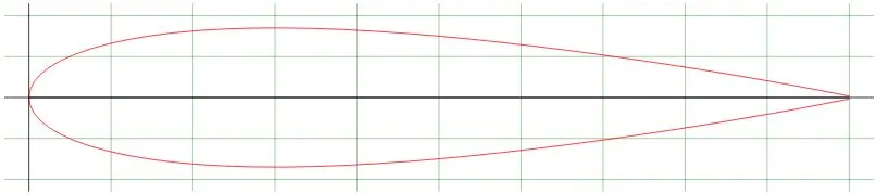
- The NACA 0017 airfoil is symmetrical, 00 indicates that it has no camber.The 17 indicates that the airfoil has a 17% thickness to chord length ratio it is 17% as thick as it is long.
Angle of attack :
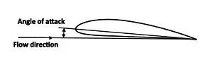
In fluid dynamics, angle of attack is the angle between a referance line on abody (often the chord line of an airfoil) and the vector representing the relative motion between the body and the fluid through which it is moving. Angle of attack is the angle between the body's referance line and the oncoming flow. This article focuses on the most common application, the angle of attack of a wing or airfoil moving through air.
Stall angle :
In fluid dynamics, a shall is a reduction in the lift coefficent generated by a foil as angle of attack increases. This occurs when the critical angle of attack of the foil is exceeded. The crictical angle of attack is typically about 15 degree, but it vary significantly depending on the fluid, foil and reynolds number.
CREATE A NACA 0017 AIRFOIL :
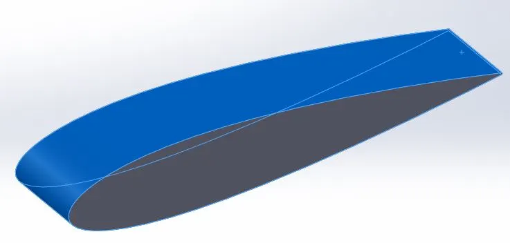
Download the NACA 0017 airfoil coordinates and save it to text document file. To import the x,y&z coordinates in solidworks through the insert option. After that, curve has appeared.
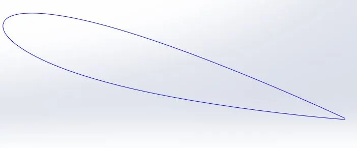
To create a 2d airfoil by using convert entities. For each case the airfoil gets rotates in 2 degree and extruding it.
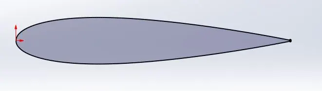
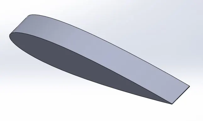
Extruded the 2d airfoil in z direction at distance of 0.05 m
 '
'
CREATE FLUID FLOW DOMAIN
Wizard analysis type
Unit system - SI
Flow type - External
Physical feature :
Time dependent
Total analysis time - 5 second
Output time step - 1 second
Working fluid - Air
Pressure - 101325 pascals
Temperature - 293 K
Velocity on X direction - 600m/sec
Air passes over the selected surface on X direction for all different angle of attack, there is zero velocity on Y & Z direction.
 '
'
DISCRITIZATION OF DOMAIN :
The process of discritize the mathematical domain is divided into finite cells or elements is called meshing. The whole constrainted domain is splited into small piece, the governing eqaution is solved in each element or cell.
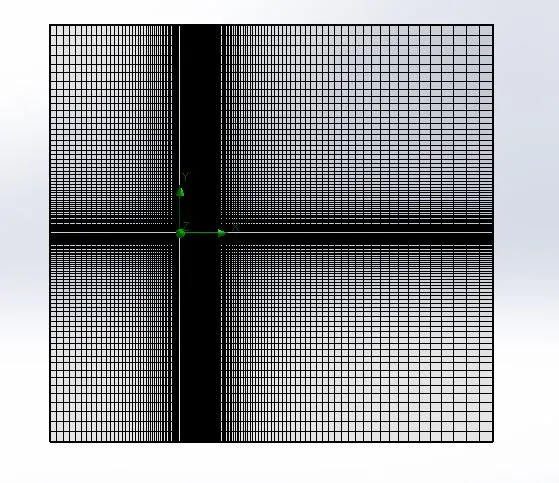
In this case is external flow, the bounding box fully descritization is created. Actually, the air flows over a selected surface
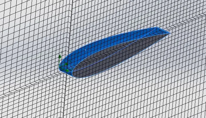
Near the selected surface we refine the mesh element size without changing element type. See the below figure, it creates the fine mesh near a flow over surface.
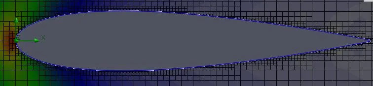
Mesh specifications :
Element type : Hexahedral
Number of elements/cells : 25430
Contact cells with surface : 4584
INITIAL AND BOUNDARY CONDITIONS :
1) We created the bounding box by using the wizard option, to provide the inlet velocity of ar is 600 m/s. The gauge pressure or referance pressure is default set to be 1 atm pressure in pascals at outlet.
2) Provide set manually flow simulation end time along the length of the domain with set the output per time.
3) Y & Z direction velocity is zero, we only focus on X direction over the airfoil.
POST PROCESSING :
CASE 1
Angle of attack is 0 degree
Pressure contour for 0 angle of attack
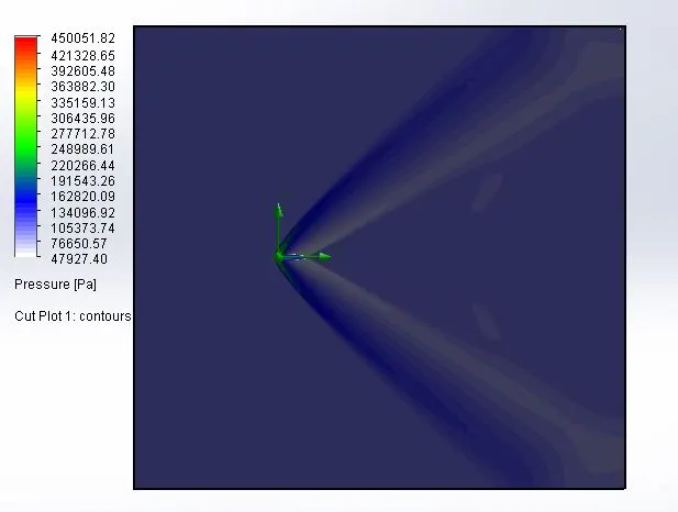
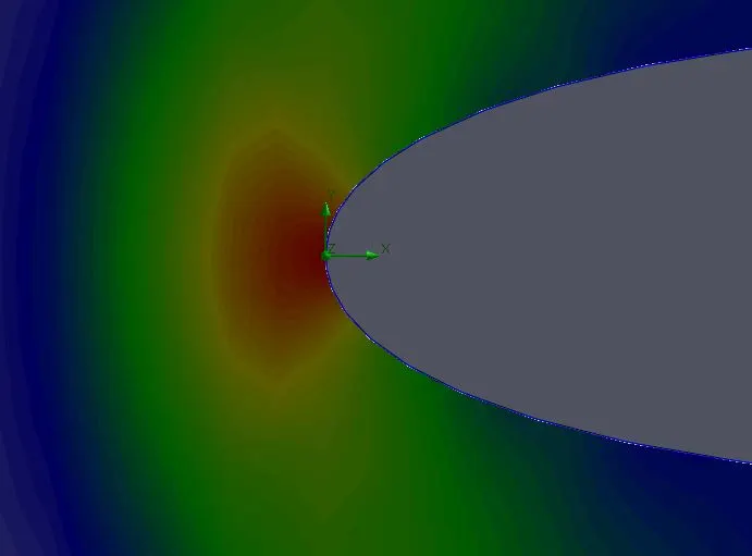
1) The velocity of air is passed through the domain in positive x direction, the air strike gets on the airfoil leading edge. After that, the air passed over the airfoil, due to tearoff the air from influencing of airfoil shape. At the nose of the airfoil, the velocity is drastically reduced and pressure is increased.
2) At the nose of the airfoil pressure is 3 to 4 times higher than the atmospheric pressure. The upper surface flow velocity is high compare to lower surface flow, the upper surface craetes a low pressure and lower surface creates a high pressure.
3) Over the upper surface, the boundary layer has been formed due to viscosity and shear stress between air and airfoil surface. At end of the trailing edge, the separation of boundary layer is formed that point pressure is reduced, velocity is increased. When we closely watched the legend table, how pressure has changed through the domain from inlet to outlet.
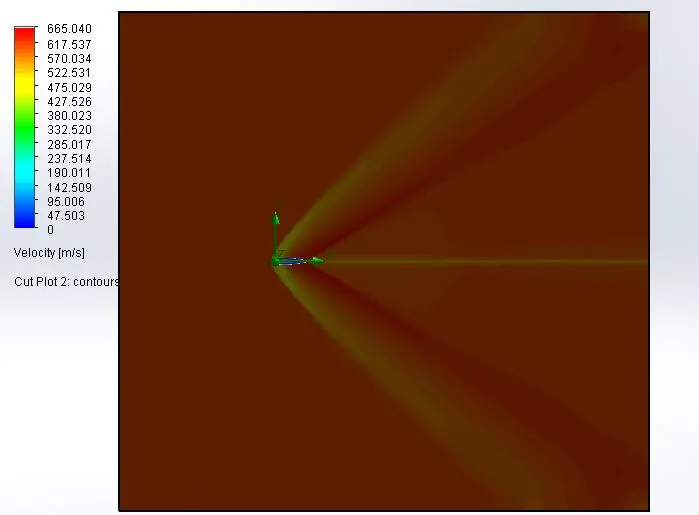
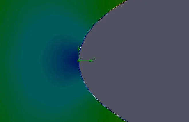
Velocity contour for 0 angle of attack
 '
'
The inlet velocity is 600 m/s but the highest velocity in our case is around 660 m/s, due to bernoullie's principle. At the strike of air infornt of the nose, the velocity is almost 0, pressure is high
Convergence iteration achieved
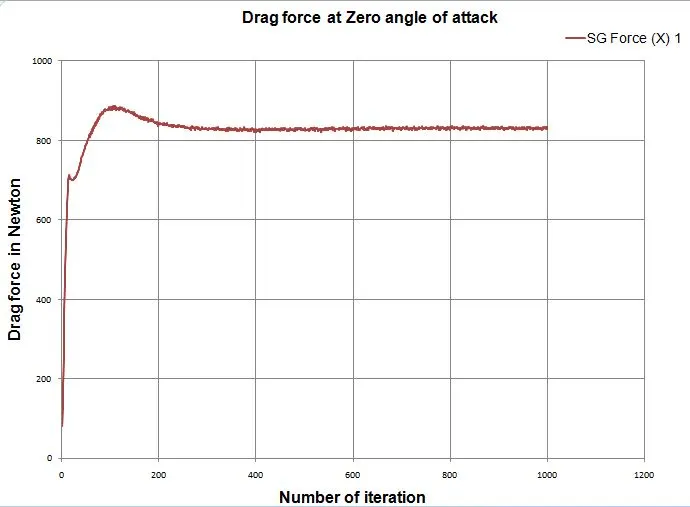
1) The average drag force is around 830 N and Convergence had achieved at 265 iteration
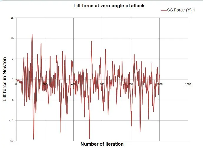
2) The average lift force for 0 degree angle of attack is around 0.18 N, But solution could not be converged over the 1000 iteration. Because of lift force is heaped in positive and negative values from preceded iteration to succeeded iteration.
3) Iteration means number of times the governing equations will formed on the different boundary condition values.

Drag force plot for 0 angle of attack
1) A drag force is the resistance force caused by the motion of a body through a fluid, such as water or air. A drag force acts opposite to the direction of the oncoming flow velocity.
2) After the 265 iteration solution get converged (or) the solution will comes under the residual value.
3) SG Force (X)1 legend is representated the drag force value over the each iteration.
Lift force plot for 0 angle of attack
1) A fluid flowing around the surface of an object exerts a force on it. Lift is the component of this force that is perpendicular to the oncoming flow direction.
2) At 265 iteration, drag force get coverged, but lift force had not been coverged till 1000 iteration. Because, NACA 0017 airfoil is symmetrical shape and also zer0 angle of attack, the pressure changed subsequently over the even iteration.
3) SG Force (Y) 1 legend represents by lift force value changes over the each iterations.
Goals for finding drag and lift force
We focus on airfoil flow surface from leading edge to trailling edge, the goals are drag force and lift force. The drag force is parallel to angle of attack vector and lift force is perpendicular to the angle of attack vector.

CASE 2
Angle of attack is 2 degree
Pressure contour for 2 angle of attack
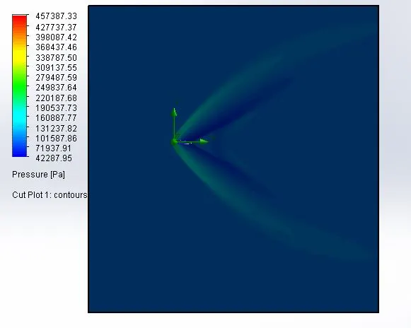
The maximum pressure is higher than the previous case. The airfoil is rotate clockwise direction about the nose point at 2 degree, the lower surface pressure slightly higher than previous model and upper surface pressure is slightly lesser than previous one. The object always try to the low pressure region due to high pressure at bottom surface.
Moreover, closely watch the pressure legend box, the pressure range is increased compare to previous one.
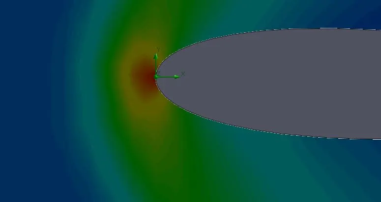
Velocity contour for 2 angle of attack
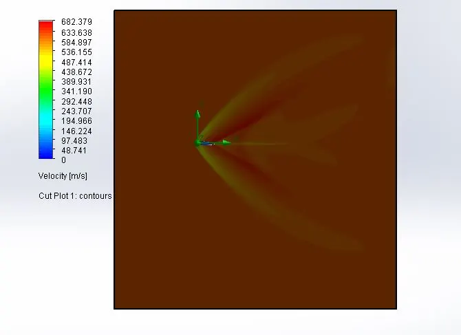
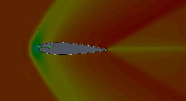
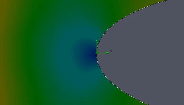
The maximum velocity is increased and maximum velocity at upper surface near the trailling edge. The velocity range also increased. At nose, the velocity is close to zero, its showm in below figure.
Convergence iteration achieved
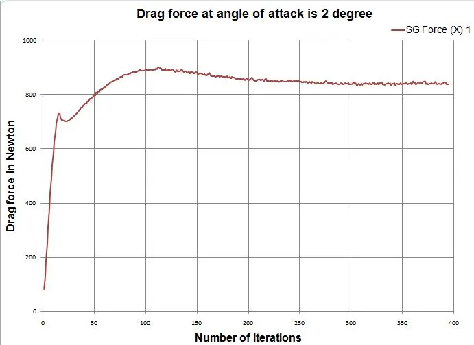
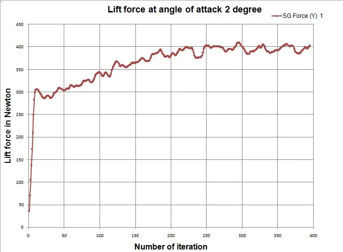
Both the goals gets converged, the drag force is converged around 280 iterations and the lift force is converged around 336 iterations.

Drag force plot for 2 angle of attack
The drag force is slightly increased due to increased the angle of attack from 0 degree to 2 degree of airfoil.
 '
'
Lift force plot for 2 angle of attack
The lift force is drastically increased, this time over the each and every iteration values are positive.
Goals for finding drag and lift force
We focus in two goals, one is drag force on the airfoil flow surface and another one is lift force on the airfoil flow surface. The progress is fully completed and result is acceptable one.

CASE 3
Angle of attack is 4 degree
Pressure contour for 4 angle of attack
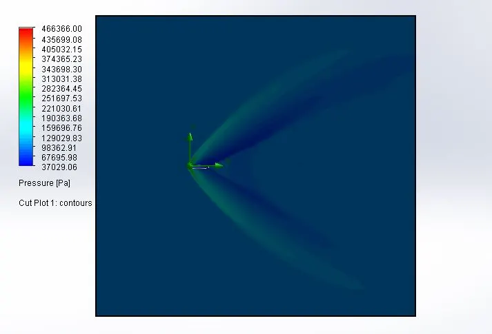
The pressure range is increased compare to previous cases. The angle of attack is increased 4 degree from the horizontal line, the lower surface pressure is high compare to previous both cases. So that lift force always rised and drag force also increased.
Velocity contour for 4 angle of attack
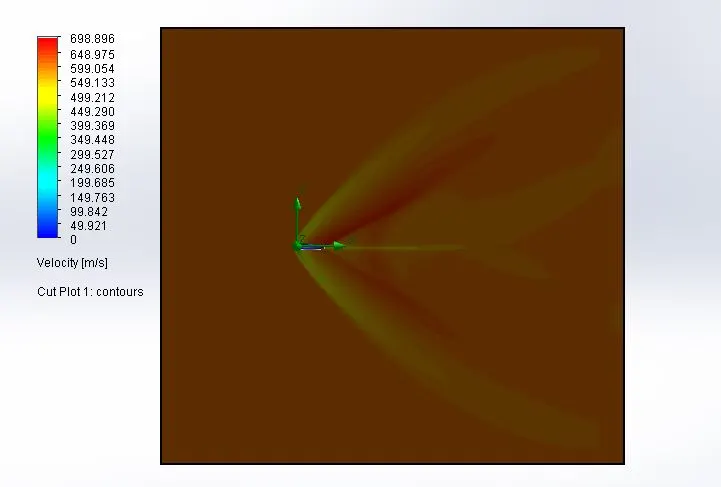
The velocity is increased at upper surface of the airfoil, then only pressure has to be reduced.
Convergence iteration achieved
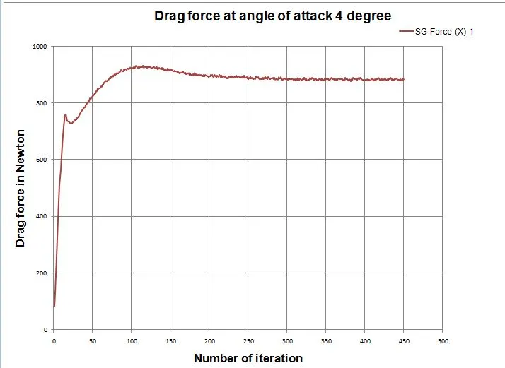
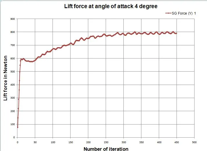
Both the goals gets converged, the drag force is converged around 244 iterations and the lift force is converged around 362 iterations.
The drag force converged earlier iteration compared to case 2, but the lift force takes some more iteration to get converged.

Drag force plot for 4 angle of attack
The drag force is slightly increased compared to previous cases.
Lift force plot for 4 angle of attack
The lift force also increased compared to previous cases due to increasing the angle of attack.
Goals for finding drag and lift force
We focus in two goals, one is drag force on the airfoil flow surface and another one is lift force on the airfoil flow surface. The progress is fully completed and result is acceptable one comparing to previous cases.

CASE 4
Angle of attack is 6 degree
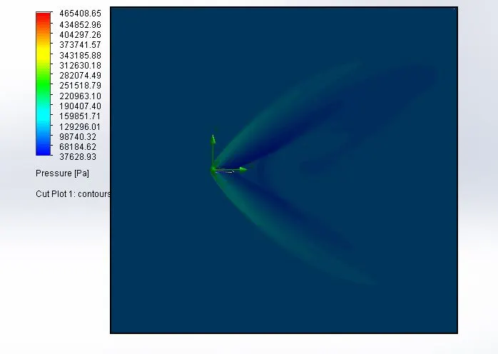
Pressure contour for 6 angle of attack
The angle of attack is increased to 6 degree, pressure range is increased and also pressure difference is high compare to lower and upper surface.
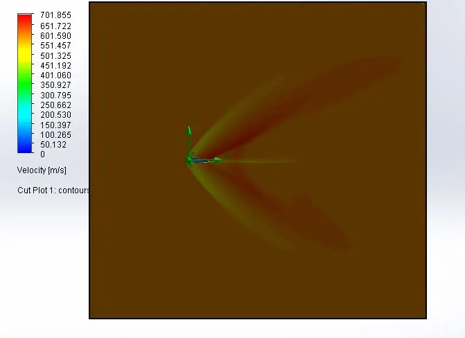
Velocity contour for 6 angle of attack
The velocity range is increased, the nose point velocity is almost zero. The trailling edge of the upper edge velocity is high due to low pressure.
Convergence iteration achieved
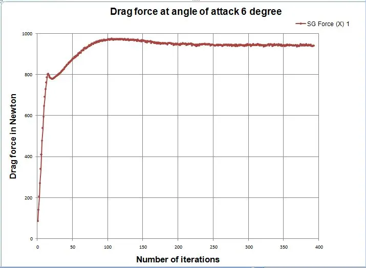
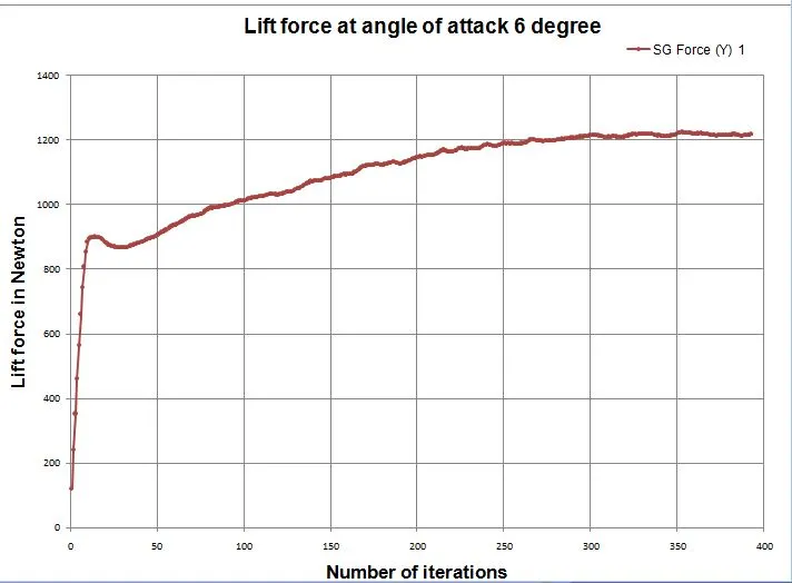
Both the goals gets converged, the drag force is converged around 200 iterations and the lift force is converged around 361 iterations.
The drag force converged earlier iteration compared to case 3, lift force is coverged earlier one iteration from previous case.

Drag force plot for 6 angle of attack
Drag force is increaseed, due to increased the angle of attack of air. The drag force is one on the components in aerodynamic forces.
Lift force plot for 6 angle of attack
Lift force is also increased, the lower surface pressure is high and upper surface pressure is low.
Goals for finding drag and lift force
We focus in two goals, one is drag force on the airfoil flow surface and another one is lift force on the airfoil flow surface. The progress is fully completed and result is acceptable one comparing to previous cases.

CASE 5
Angle of attack is 8 degree
Pressure contour for 8 angle of attack
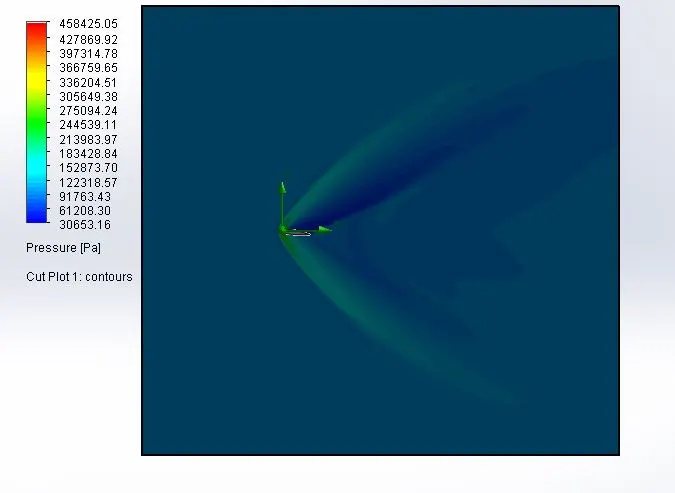
The minimum pressure is reduced, maximum pressure also be reduced compared to previous cases. Same principle was happed, the lower surface pressure is high and upper surface pressure is low with boundary layer separation has happening. Moreover, relative velocity is difference in upper and lower surface.
Velocity contour for 8 angle of attack
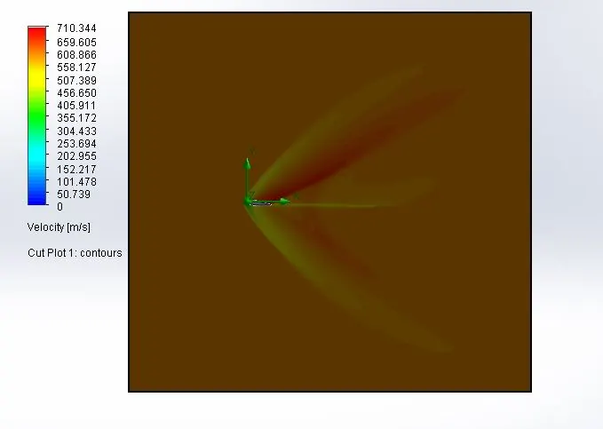
At the point of nose the velocity is close to zero, the velocity high at the upper surface of the airfoil.
Convergence iteration achieved
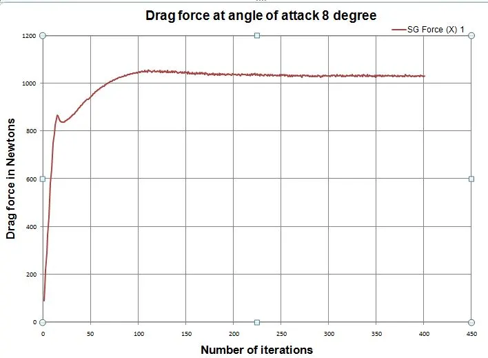
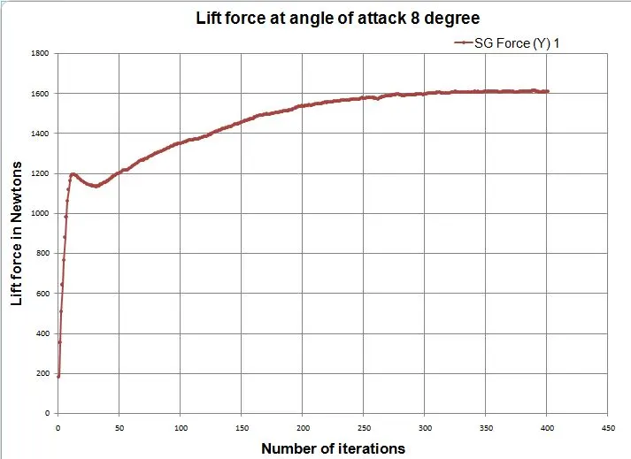
Both the goals gets converged, the drag force is converged around 158 iterations and the lift force is converged around 338 iterations.
The drag force and lift force converged earlier iteration compared to previous cases.

Drag force plot for 8 angle of attack
Lift force plot for 8 angle of attack
Goals for finding drag and lift force
We focus in two goals, one is drag force on the airfoil flow surface and another one is lift force on the airfoil flow surface. The progress is fully completed and result is acceptable one comparing to previous cases.

CASE 6
Angle of attack is 10 degree
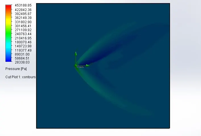
Pressure contour for 10 angle of attack
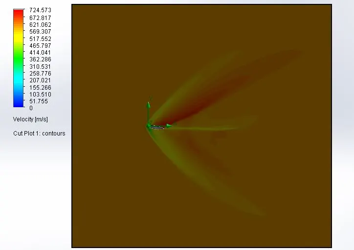
Velocity contour for 10 angle of attack
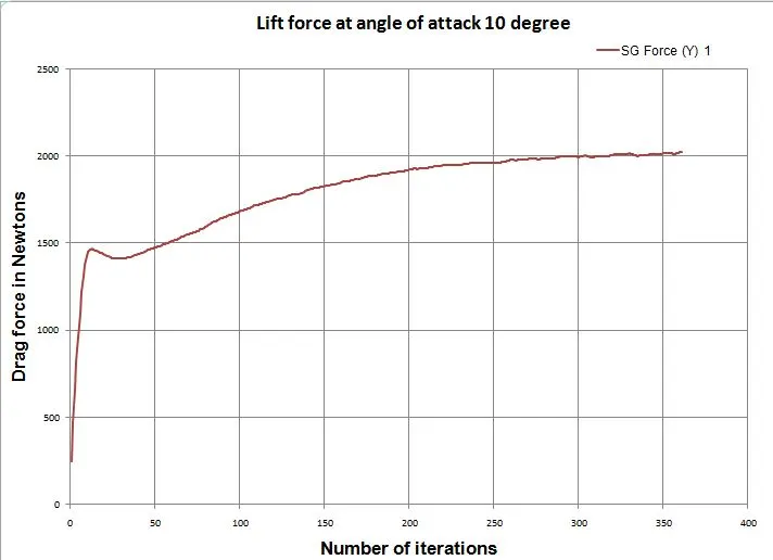
Convergence iteration achieved
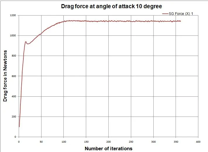
Both the goals gets converged, the drag force is converged around 158 iterations and the lift force is converged around 338 iterations.
The drag force and lift force converged almost same.

Drag force plot for 10 angle of attack
Lift force plot for 10 angle of attack
Goals for finding drag and lift force
We focus in two goals, one is drag force on the airfoil flow surface and another one is lift force on the airfoil flow surface. The progress is fully completed and result is acceptable one comparing to previous cases.

COMPARISION
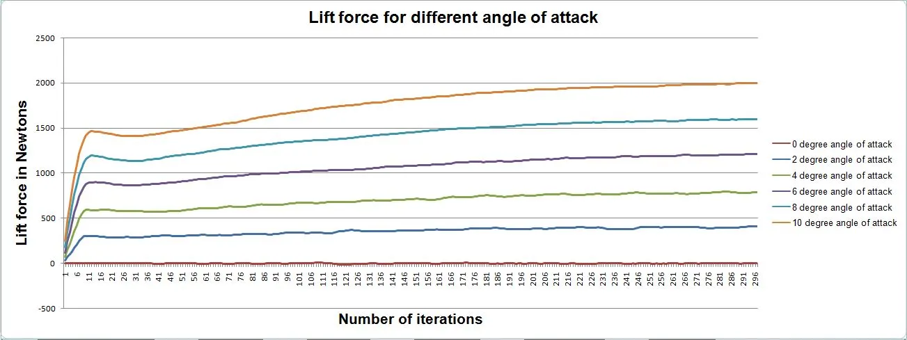
Comparing the lift force for all cases
Lift forces plot over the 300 iteration for all cases in single plot, the lift force is proportional to angle of attack till stall angle will achieved. Whenever, the angle crossing the stall, the lift force will falling dlown.
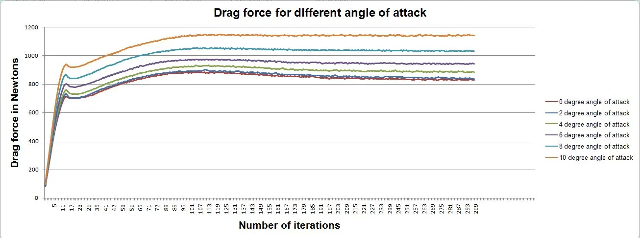
Comparing the drag forces for all cases
Drag force plot over the 300 iteration for all cases in single plot, the drag force is proportional to angle of attack.
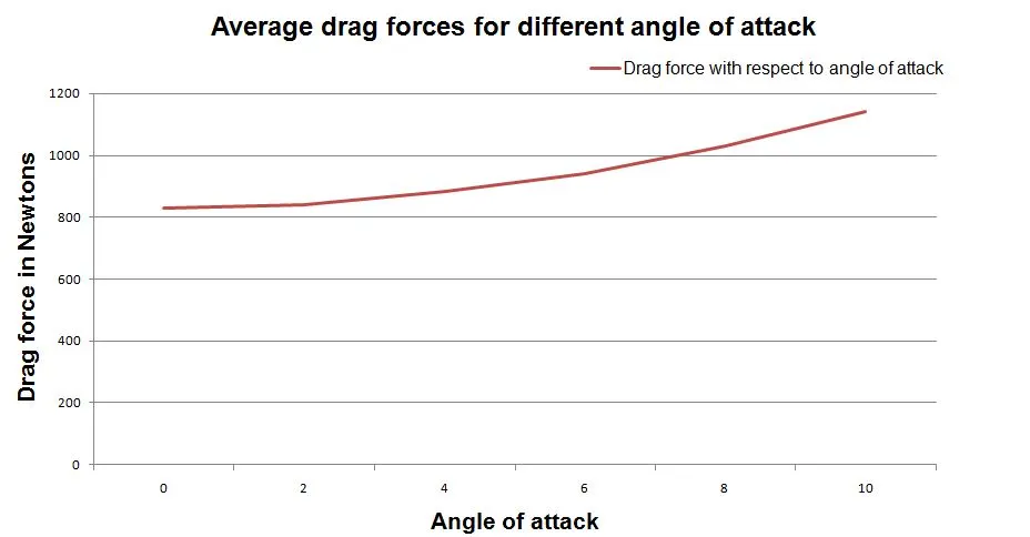
Average drag forces for all cases
To plot the image for only which average drag forces of different angle of attack. The curve looks like slightly in quadratic variation with respect to angle of attack.
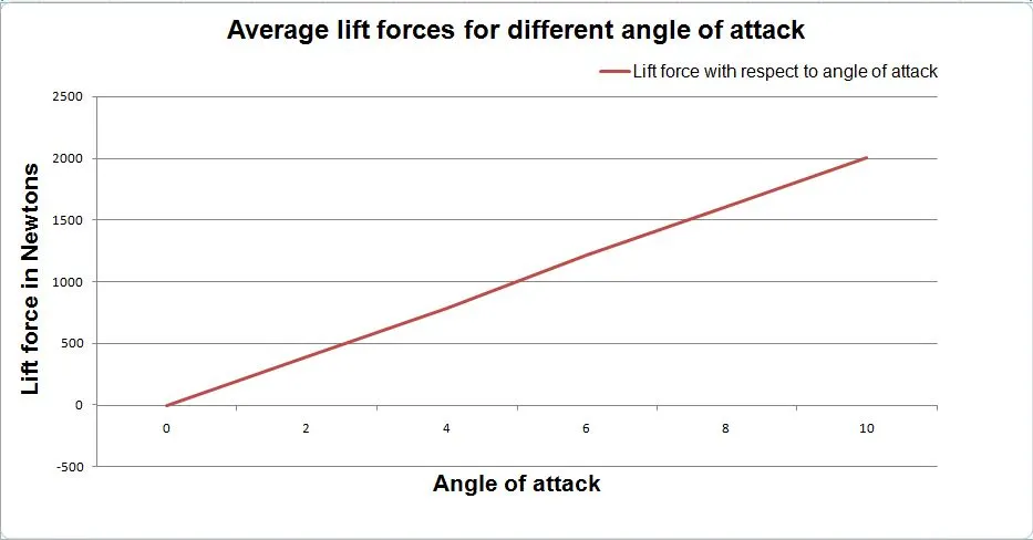
Average lift forces for all cases
To plot the image for only which average lift forces of different angle of attack. The curve looks linear variation with respect to angle of attack.
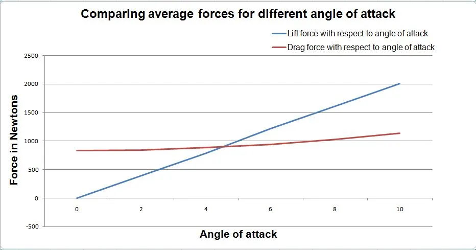
Comparing the average lift and drag forces for all cases
Superimposing the average drag forces and lift forces with respect to angle of attack
OBSERVATION :
1) It satisfied the bernoullie's principle, it states that an increase in the speed of a fluid occurs simultaneously with a decrease in static pressure or a decrease in the fluid's potential energy.
2) Lift force is continuously increased when the angle of attack is increased till the stall angle will achieving.
3) Drag force is proportional to angle of attack for all the cases.
4) Separation of boundary layer on the upper surface is varying when the angle of attack is varied
5) Relative velocity is varing on upper and lower surface.
CONCLUSION :
Finally, ran the flow simulation over a airfoil is successfully did for all cases. The drag force and lift force is acceptable value have achieved. Make a contour plot for pressure and velocity is varying along the entire domain. Result had been converged for all cases except lift force for an zero angle of attack.
REFERANCE :
1) https://en.wikipedia.org/wiki/Airfoil
2) https://en.wikipedia.org/wiki/NACA_airfoil